Intel SC5300 User Manual
Hide thumbs
Also See for SC5300:
- Installation manual (14 pages) ,
- Technical product specification (101 pages) ,
- Install manual (34 pages)

Related Manuals for Intel SC5300


Summary of Contents for Intel SC5300
-
Page 1: User Guide
Intel® Server Chassis SC5300, SC5300 LX and SC5300 BRP User Guide A Guide for Technically Qualified Assemblers of Intel® Identified Subassemblies/Products Order Number: C51486-001... - Page 2 Intel’s own chassis are designed and tested to meet the intended thermal requirements of these components when the fully integrated system is used together. It is the responsibility of the system integrator that chooses not to use Intel developed server building blocks to consult vendor datasheets and operating parameters to determine the amount of airflow required for their specific application and environmental conditions.
-
Page 3: About This Manual
Manual Organization Chapter 1 provides a brief overview of the Server Chassis SC5300. In this chapter, you will find a list of the server chassis features, photos of the product, and product diagrams to help you identify components and their locations. -
Page 4: Additional Information And Software
BIOS settings and chipset Specification at information http://support.intel.com/support/motherboards/server/chassis/ sc5300/sb/CS-012478.htm. If you just received this product and need to Intel® Server Chassis SC5300 Quick Start User’s Guide in install it the product box For the latest product information http://support.intel.com/support/motherboards/server/chassis/ SC5300 Accessories or other Intel server products http://support.intel.com/support/motherboards/server/sb/CS-... -
Page 5: Warnings
We recommend that you perform all procedures in this chapter only at an ESD workstation. If one is not available, provide some ESD protection by wearing an antistatic wrist Intel® Server Chassis SC5300 User Guide... -
Page 6: Safety Cautions
Unplug all AC power cords from the system or from wall outlets. Label and disconnect all cables connected to I/O connectors or ports on the back of the system. Provide some electrostatic discharge (ESD) protection by wearing an antistatic wrist Intel® Server Chassis SC5300 User Guide... - Page 7 Provided with a properly grounded wall outlet. Provided with sufficient space to access the power supply cord(s), because they serve as the product’s main power disconnect. Intel® Server Chassis SC5300 User Guide...
-
Page 8: Wichtige Sicherheitshinweise
Preface Wichtige Sicherheitshinweise Lesen Sie zunächst sämtliche Warn- und Sicherheitshinweise in diesem Dokument, bevor Sie eine der Anweisungen ausführen. Beachten Sie hierzu auch die Sicherheitshinweise zu Intel- Serverplatinen und -Servergehäusen unter http://support.intel.com/support/motherboards/server/sb/CS-010770.htm Benutzer können am Netzgerät dieses Produkts keine Reparaturen vornehmen. Das Produkt enthält möglicherweise mehrere Netzgeräte. - Page 9 über ausreichend Platz verfügen, um Zugang zu den Netzkabeln zu gewährleisten, da der Stromanschluß des Produkts hauptsächlich über die Kabel unterbrochen wird. 重要安全指导 在执行任何指令之前,请阅读本文档中的所有注意事项及安全声明。和/或http://support.intel Intel Server Boards and Server 上的 .com/support/motherboards/server/sb/CS-010770.htm Chassis Safety Information (《Intel 服务器主板与服务器机箱安全信息》)。 Intel® Server Chassis SC5300 User Guide...
- Page 10 Preface Consignes de sécurité Lisez attention toutes les consignes de sécurité et les mises en garde indiquées dans ce document avant de suivre toute instruction. Consultez Intel Server Boards and Server Chassis Safety Information sur le site http://support.intel.com/support/motherboards/server/sb/CS-010770.htm Le bloc d'alimentation de ce produit ne contient aucune pièce pouvant être réparée par l'utilisateur.
-
Page 11: Instrucciones De Seguridad Importantes
Instrucciones de seguridad importantes Lea todas las declaraciones de seguridad y precaución de este documento antes de realizar cualquiera de las instrucciones. Vea Intel Server Boards and Server Chassis Safety Information en http://support.intel.com/support/motherboards/server/sb/CS-010770.htm El usuario debe abstenerse de manipular los componentes de la fuente de alimentación de este producto, cuya reparación debe dejarse exclusivamente en manos de personal técnico... - Page 12 Provisto de una toma de tierra correctamente instalada. Provisto de espacio suficiente como para acceder a los cables de alimentación, ya que éstos hacen de medio principal de desconexión del sistema. Intel® Server Chassis SC5300 User Guide...
- Page 13 È consigliabile l'uso di guanti di protezione. Esiste il pericolo di un esplosione se la pila non viene sostituita in modo corretto. Utilizzare solo pile uguali o di tipo equivalente a quelle consigliate dal produttore. Per disfarsi delle pile Intel® Server Chassis SC5300 User Guide xiii...
- Page 14 In caso di temporali, scollegare le linee di comunicazione dal modem. Dotata di una presa a muro correttamente installata. Dotata di spazio sufficiente ad accedere ai cavi di alimentazione, i quali rappresentano il mezzo principale di scollegamento del sistema. Intel® Server Chassis SC5300 User Guide...
-
Page 15: Table Of Contents
Kit Contents..........................1 Feature Summary ........................1 Chassis Front View SC5300 Base Front View ............... 2 Chassis Front View SC5300 LX with Hot Swap Components........3 Front Panel Controls and Indicators................4 Base Chassis Rear View....................5 Base Redundant Power Chassis Rear View ..............6 Chassis Side View...................... - Page 16 Chassis Subassembly Products ..........66 Extent of Limited Warranty....................66 Warranty Limitations and Exclusions ..................67 Limitations of Liability ....................67 How to Obtain Warranty Service................... 68 Telephone Support....................... 68 Returning a Defective Product ..................68 Intel® Server Chassis SC5300 User Guide...
- Page 17 Figure 4. Pedestal Controls and Indicators.................. 4 Figure 5. Intel® Server Chassis SC5300 Base Chassis Rear View ..........5 Figure 6. Intel® Server Chassis SC5300 BRP and SC5300 LX Chassis Rear View ....6 Figure 7. Intel® Server Chassis SC5300 Side View ..............7 Figure 8.
- Page 18 Table 5. 730-W Power Supply System Output Capability............52 Table 6. Environmental Specifications ..................53 Table 7. Power Usage Worksheet 1 ..................56 Table 8. Power Usage Worksheet 2 ..................57 Table 9. Product Certification Markings ..................59 xviii Intel® Server Chassis SC5300 User Guide...
-
Page 19: Chassis Description
This document applies to the Intel Server Chassis SC5300 Base, Intel® Server Chassis SC5300 Base Redundant Power (BRP) and Intel® Server Chassis SC5300 LX. Kit Contents The chassis subassembly kit includes this User Guide, one power cord, and a box that includes four chassis feet, a FDD plastic bezel, 10 extra hard disk drive rail O-rings, 10 extra CD rail O-rings, a power cord retainer, an L-gasket, bumpers, a tie-down and four different types of mounting screws. -
Page 20: Chassis Front View Sc5300 Base Front View
H. 5.25-inch Device Bays (3) Front Panel USB/Serial B Fixed Drive Cage – 4-Drive (accessory) Fixed Drive Cage – 6 –Drive Real Serial B Connector Figure 2. Intel® Server Chassis SC5300 Base Front View Intel® Server Chassis SC5300 User Guide... -
Page 21: Chassis Front View Sc5300 Lx With Hot Swap Components
Chassis Description Chassis Front View SC5300 LX with Hot Swap Components TP00557 Hot Swap Power Supply/Second Hot Swap Power Supply (accessory) PCI Add-in Card Panel C. Processor Air Duct D. PCI Air Duct Hot Swap Fans – Large (2) Hot Swap Fans – Small (2) G. -
Page 22: Front Panel Controls And Indicators
Off (also Sleep S4) Status Green System ready Green BLINK System ready, but degraded: some CPU fault, DIMM killed Critical alarm: Critical power module failure, critical fan failure, Amber voltage (power supply), voltage and thermal fault Intel® Server Chassis SC5300 User Guide... -
Page 23: Base Chassis Rear View
C. Expansion Slot Covers D. PCI Add-in Card Panel PCI Card Latch Rear Serial B Connector* G. ICBM or SCSI Knockout H. AC Power Connector Figure 5. Intel® Server Chassis SC5300 Base Chassis Rear View Intel® Server Chassis SC5300 User Guide... -
Page 24: Base Redundant Power Chassis Rear View
Rear Serial B Connector* G. ICBM or SCSI Knockout H. Power Supply Filler Panel * Items shown may be different in your chassis. Figure 6. Intel® Server Chassis SC5300 BRP and SC5300 LX Chassis Rear View Intel® Server Chassis SC5300 User Guide... -
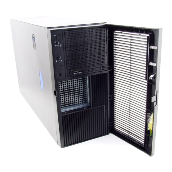
Page 25: Chassis Side View
Chassis Description Chassis Side View TP00533 Figure 7. Intel® Server Chassis SC5300 Side View Peripherals 5.25-in Half-height Peripheral Bays Note: One multi-purpose 5.25-in drive carrier is included with the chassis. This drive carrier can hold either a floppy drive (by removing the knock-out) or a fixed drive. -
Page 26: Accessories And Order Codes
Chassis Description Accessories and Order Codes Spares and Accessories are detailed in the configuration guide for the server board. For a complete list of Spares and Accessories, refer to the configuration guide stored on the Intel support site at: http://intel.com/support/motherboards/server/ Table 3. -
Page 27: Setting Up The Chassis
Label and disconnect all peripheral cables and all telecommunication lines connected to I/O connectors or ports on the back of the chassis. Provide some electrostatic discharge (ESD) protection by wearing an antistatic wrist strap attached to chassis ground—any unpainted metal surface—when handling components. Intel® Server Chassis SC5300 User Guide... -
Page 28: Warnings And Cautions
Do not slide board over any surface. For proper cooling and airflow, always install the access cover before turning on the server. Operating it without the cover in place can damage system parts. Intel® Server Chassis SC5300 User Guide... -
Page 29: Remove Primary Access Cover
4. Press the latch (letter “B”) and slide the Primary Access Cover toward the rear of the chassis. 5. Lift the Primary Access Cover outward to remove it. TP00912 Figure 8. Removing the Access Cover Intel® Server Chassis SC5300 User Guide... -
Page 30: Remove Bezel Assembly
Assembly does not immediately disconnect from the chassis, then tap the left-hand side of the Bezel Assembly to disengage the bezel hooks on the right-hand side of the chassis. TP00537 Figure 9. Removing Bezel Assembly Intel® Server Chassis SC5300 User Guide... -
Page 31: Remove Air Ducts
Remove Air Ducts 1. Press the latch (letter “A”) and remove the PCI air duct (letter “B”) from the chassis. 2. Remove the processor air duct (letter “C”). TP00529 Figure 10. Removing Air Ducts Intel® Server Chassis SC5300 User Guide... -
Page 32: Remove Hot Swap Fans
1. Press latch (letter “A”) on fan and pull on handle to remove Hot Swap Fan from chassis. 2. Repeat Step 1 for remaining hot swap fans. TP00908 Figure 11. Removing Hot Swap Fans Intel® Server Chassis SC5300 User Guide... -
Page 33: Route Power And Data Cables To The Fixed Drives
Route the P6 and P7 power cables to the four-drive bay. Route the SATA drive power cables to whichever drive bay is using SATA fixed drives. To Upper Device Bay To Server Board To 4-Drive Cage To 6-Drive Cage TP00528 Figure 13. Routing Power Cables to Fixed Drives Intel® Server Chassis SC5300 User Guide... -
Page 34: Install 3.5-Inch Floppy Drive
1. Press pair of slides inward (letter “A”) to release and pull slide/filler panel assembly out of upper device bay. Remove EMI panel from bracket (letter “B”). TP00535 Figure 15. Removing Slide/Filler Panel Assembly from Upper Device Bay Intel® Server Chassis SC5300 User Guide... -
Page 35: Figure 16. Installing Slides On 3.5-In Floppy Drive
Figure 16. Installing Slides on 3.5-in Floppy Drive 4. Insert the floppy drive/slide assembly partially into the upper device bay. Connect power and data cables. 5. Finish inserting the floppy drive/slide assembly into the chassis until the slides lock into place. Intel® Server Chassis SC5300 User Guide... -
Page 36: Install Dvd Or Cd-Rom Drive
DVD or CD-ROM drive. TP00536 Figure 18. Installing a DVD or CD-ROM Drive 3. Insert the drive/slide assembly into the upper device bay until the slides lock into place. 4. Connect power and data cables. Intel® Server Chassis SC5300 User Guide... -
Page 37: Install Fixed Hard Drive(S)
Take care, however, to position the drive cage horizontally before opening the drive cage doors or the drive rails will spill out. 2. Loosen the captive screw (letter “A”). Open the upper door (letter “B”). TP00919 Figure 20. Unlocking and Opening Upper Drive Cage Door Intel® Server Chassis SC5300 User Guide... -
Page 38: Figure 21. Opening Lower Drive Cage Door
Setting Up the Chassis 3. Open the lower door. TP00920 Figure 21. Opening Lower Drive Cage Door 4. Remove a pair of device slides from the drive cage. TP00563 Figure 22. Remove Slides from Drive Cage Door Intel® Server Chassis SC5300 User Guide... -
Page 39: Figure 23. Installing Device Slides To Hard Drive
The top of the drive is in the same orientation as the arrow in the following illustration. TP00923 Figure 24. Inserting Drive/Slide Assembly into Drive Cage 7. Repeat steps 4-5 for installation of additional hard drives into drive cage. Intel® Server Chassis SC5300 User Guide... -
Page 40: Figure 25. Closing Lower Door Of Fixed Drive Cage
9. Close the upper door of drive cage. TP00550 Figure 26. Closing Upper Door of Fixed Drive Cage 10. Tighten the thumb screw. Install power and data cables to connectors on hard drive(s). TP00551 Figure 27. Tightening Thumb Screw Intel® Server Chassis SC5300 User Guide... -
Page 41: Install Hot Swap Drive(S)
Ensure that the connector end of the hard drive is facing the back of the drive carrier. The label side of the hard drive should be facing up in the drive carrier. TP00929 Figure 30. Securing Hard Drive to Drive Cage Intel® Server Chassis SC5300 User Guide... -
Page 42: Install Hot Swap Fans
Figure 32. Installing a Hot Swap Fan Install Server Board See your Intel® Server Board Quick Start User’s Guide for server board installation instructions and installation of the back panel I/O shield. Use the mounting screws, bumpers and standoffs (if... -
Page 43: Install Air Dam
Install Air Dam NOTE This step only applies if an Intel® Server Board SE73020SP2 or Intel® Server Board SE7525GP2 is to be installed in the chassis. 1. Remove adhesive strip from back of Air Dam. TP00547 Figure 33. -
Page 44: Connect Cables To Server Board
Setting Up the Chassis Connect Cables to Server Board 1. See your Intel® Server Board User Guide or Quick Start User’s Guide for cable connection locations. NOTE Use caution in routing cables to ensure that cables do not obstruct airflow from the fans. -
Page 45: Install Add-In Board(S)
1. Press on two plastic tabs (letter “A”) and remove PCI Add-in Card Retainer, if not removed in a previous step. TP00553 Figure 36. Remove PCI Add-in Card Retainer Intel® Server Chassis SC5300 User Guide... -
Page 46: Figure 37. Preparing The Chassis For A Pci Add-In Board
Place board on anti-static surface. Record the type and serial number of the add-in board in your equipment log. Set jumpers or switches on the board according to manufacturer’s instructions. Intel® Server Chassis SC5300 User Guide... -
Page 47: Figure 38. Installing An Add-In Board
(letter “A”). Close back panel PCI Add-in Card Retention Device (letter “B”). TP00555 Figure 38. Installing an Add-in Board 5. Repeat Step 4 until all PCI add-in cards are installed. Intel® Server Chassis SC5300 User Guide... -
Page 48: Figure 39. Replacing Pci Add-In Card Retainer
Setting Up the Chassis 6. Reinstall the PCI Add-in Card Retainer. TP00691 Figure 39. Replacing PCI Add-in Card Retainer 7. Attach cables if necessary. Intel® Server Chassis SC5300 User Guide... -
Page 49: Install Air Ducts
Step 2. TP00545 Figure 40. Removing Inner Plastic Air Baffle from Processor Air Duct 2. If you are installing an Intel® Server Board SE7520BD2 or SE7520AF2, remove the outer plastic air baffle. NOTE Leave the outer air baffle in place if you are installing an Intel® Server Board SE7320SP2 or SE7525GP2. -
Page 50: Figure 42. Installing Air Ducts
3. Install Processor Air Duct into chassis (letter “A”). Install PCI Air Duct (letter “B”) and latch (letter “C”) into place. NOTE The Processor Air Duct interlocks with the PCI Air Duct in two places before latching into place. TP00562 Figure 42. Installing Air Ducts Intel® Server Chassis SC5300 User Guide... -
Page 51: Install An Additional Hot Swap Power Supply Module
Figure 43. Removing Power Supply Filler Panel 2. Insert power supply module until it clicks into place. Secure with screw (letter “A”) if shipping chassis to another location TP00544 Figure 44. Installing Additional Hot Swap Power Supply Module Intel® Server Chassis SC5300 User Guide... -
Page 52: Install Bezel Assembly
3. Fit the right edge of the Bezel Assembly against the right side of chassis and engage plastic bezel hooks (letter “C”) into raised metal slots at chassis edge. 4. Rotate Bezel Assembly toward chassis and latch the two plastic tabs (letter “D”) on left side of Bezel Assembly to chassis. Intel® Server Chassis SC5300 User Guide... -
Page 53: Install Primary Access Cover
Setting Up the Chassis Install Primary Access Cover 1. Slide Primary Access Cover on chassis. 2. Latch securely to the chassis. TP00915 Figure 46. Installing the Access Cover Intel® Server Chassis SC5300 User Guide... -
Page 55: Maintaining Your Server
Otherwise, personal injury or equipment damage can result. Hazardous voltage, current, and energy levels are present inside the power supply. There are no user-serviceable parts inside it; servicing should be done by technically qualified personnel. Intel® Server Chassis SC5300 User Guide... - Page 56 Do not slide board over any surface. For proper cooling and airflow, always install the access cover before turning on the server. Operating the server without the cover in place can damage system parts. Intel® Server Chassis SC5300 User Guide...
-
Page 57: Replacing A Fixed Fan
Figure 47. Removing a Fixed Fan 4. Install new 92-mm or 120-mm Fixed Fan. 5. Reconnect fan cable to server board. 6. Replace Primary Access Cover (see “Install Primary Access Cover” in Chapter 2 for step-by- step instructions). Intel® Server Chassis SC5300 User Guide... -
Page 58: Replacing A Hot Swap Fan
3. Press latch (letter “A”) on fan and pull on handle to remove Hot Swap Fan from chassis. TP00908 Figure 48. Removing a Hot Swap Fan 4. Insert new Hot Swap Fan. TP00995 Figure 49. Installing a Hot Swap Fan Intel® Server Chassis SC5300 User Guide... -
Page 59: Replacing The Front Panel Board
Remove and save the three screws (letter “C”) holding the front panel board to the chassis. Carefully remove the Front Panel Board. TP00690 Figure 50. Removing the Front Panel Board Intel® Server Chassis SC5300 User Guide... -
Page 60: Replacing A Fixed Power Supply
1. Disconnect all power cables from chassis after shutting down the server. 2. Remove the Primary Access Cover (see “Remove Primary Access Cover” in Chapter 2 for step-by-step instructions). 3. Disconnect all internal power cables from chassis components and server board. Intel® Server Chassis SC5300 User Guide... - Page 61 7. Secure Fixed Power Supply shield to chassis with eight screws. 8. Route the P1, P2 and P14 cables to the server board. 9. Connect the power cables to the server board, Refer to the Intel® Server Board Quick Start User’s Guide or User Guide for appropriate power connections.
-
Page 62: Replacing A Hot Swap Power Supply
3. Insert new Hot Swap Power Supply. Replace shipping screw (letter “A”) if shipping chassis to another location. TP00544 Figure 54. Installing a Hot Swap Power Supply 4. Connect power cable to replaced power supply. Intel® Server Chassis SC5300 User Guide... -
Page 63: Replacing A Power Distribution Board
Repeat this step for second Hot Swap Power Supply if one is installed. TP00558 Figure 55. Removing Hot Swap Power Supply 5. Disconnect all internal power cables from chassis components and server board. Intel® Server Chassis SC5300 User Guide... - Page 64 (letter “C”). Remove center divider from power supply cage (letter “D”). Figure 56. Removing Center Divider Intel® Server Chassis SC5300 User Guide...
- Page 65 You may have to feed the power cables through the power supply cage while removing the Power Distribution Board. TP00698 Note: Cables on back of Power Distribution Board not shown to clarify removal process. Figure 57. Removing Power Distribution Board Intel® Server Chassis SC5300 User Guide...
- Page 66 Figure 58. Securing Power Distribution Board to Power Supply Cage 9. Route the P1, P2, and P14 power cables to the server board and connect to appropriate connectors. Refer to the Intel® Server Board Quick Start User’s Guide or User Guide for the location of power connectors.
- Page 67 13. Reinstall the Air Ducts (see “Install Air Ducts” in Chapter 2 for step-by-step instructions). 14. Replace the Primary Access Cover (see “Install Primary Access Cover” in Chapter 2 for step- by-step instructions). 15. Connect power to chassis. Intel® Server Chassis SC5300 User Guide...
-
Page 69: Technical Reference
The expansion slots on the server board are rated for no more than 25 Watts for any one slot. The average current usage per slot should not exceed 13 Watts. Intel® Server Chassis SC5300 User Guide... -
Page 70: 730-W Single Power Supply Input Voltages
The expansion slots on the server board are rated for no more than 25 Watts for any one slot. The average current usage per slot should not exceed 13 Watts. Intel® Server Chassis SC5300 User Guide... -
Page 71: System Environmental Specifications
Acoustic noise 7 Bels in sound power for a typical office ambient temperature (65-75 °F). Your selection of peripherals may change the noise level. Electrostatic discharge (ESD) Tested to 15 kilovolts (kV); no component damage. Intel® Server Chassis SC5300 User Guide... -
Page 72: Equipment Log And Worksheets
Video Display Keyboard Mouse Diskette Drive A CD-ROM Drive Additional 5.25” Peripheral Hard Disk Drive Hard Disk Drive Hard Disk Drive Hard Disk Drive Hard Disk Drive Hard Disk Drive Hard Disk Drive continued Intel® Server Chassis SC5300 User Guide... - Page 73 Equipment Log and Worksheets Equipment Log (continued) Item Manufacturer Name and Model Number Serial Number Date Installed Intel® Management Module Local Control Panel Intel® Server Chassis SC5300 User Guide...
-
Page 74: Current Usage
4th Hard Drive 5th Hard Drive 6th Hard Drive Expansion Board 1 Expansion Board 2 Expansion Board 3 Expansion Board 4 Expansion Board 5 Expansion Board 6 Intel® Management Module Local Control Panel Total Current Intel® Server Chassis SC5300 User Guide... -
Page 75: Table 8. Power Usage Worksheet 2
Do not exceed a combined power output of 140 Watts for the +5 V and +3.3 V outputs. Exceeding a combined 140 Watts will overload the power subsystem and may cause the power supplies to overheat and malfunction. Intel® Server Chassis SC5300 User Guide... -
Page 76: Regulatory And Compliance Information
GB4943- CNCA Certification (China) Product EMC Compliance – Class A Compliance The Intel® Server Chassis SC5300 has been tested and verified to comply with the following electromagnetic compatibility (EMC) regulations. For information on compatible host system(s) refer to Intel’s Server Builder Web site or contact your local Intel representative. -
Page 77: Certifications / Registrations / Declarations
Listing Marks USA/Canada GS Mark Germany CE Mark Europe FCC Marking (Class A) EMC Marking (Class A) Canada VCCI Marking (Class A) Japan Regulatory Compliance Country Marking BSMI Certification Taiwan Number & Class A Warning Intel® Server Chassis SC5300 User Guide... -
Page 78: Electromagnetic Compatibility Notices
(1) this device may not cause harmful interference, and (2) this device must accept any interference received, including interference that may cause undesired operation. For questions related to the EMC performance of this product, contact: Intel Corporation 5200 N.E. Elam Young Parkway Hillsboro, OR 97124 1-800-628-8686 Intel® Server Chassis SC5300 User Guide... -
Page 79: Industry Canada (Ices-003)
Europe (CE Declaration of Conformity) This product has been tested in accordance too, and complies with the Low Voltage Directive (73/23/EEC) and EMC Directive (89/336/EEC). The product has been marked with the CE Mark to illustrate its compliance. Intel® Server Chassis SC5300 User Guide... -
Page 80: Vcci (Japan)
English translation of the notice above: 1. Type of Equipment (Model Name): On License and Product 2. Certification No.: On RRL certificate. Obtain certificate from local Intel representative 3. Name of Certification Recipient: Intel Corporation 4. Date of Manufacturer: Refer to date code on product 5. -
Page 81: Regulated Specified Components
URL: http://channel.intel.com/go/serverbuilder If you do not have access to Intel’s Web address, please contact your local Intel representative. Server Chassis (base chassis is provided with power supply and fans)UL listed. Server boardyou must use an Intel server board—UL recognized. -
Page 82: Getting Help
Telephone All calls are billed US $25.00 per incident, levied in local currency at the applicable credit card exchange rate plus applicable taxes. (Intel reserves the right to change the pricing for telephone support at any time without notice). In U.S. and Canada... - Page 83 Peru 001-916-377-0114 dialing 800-225-288; once connected, dial 800-843- Uruguay 001-916-377-0114 4481 Ecuador (Andimate) contact AT&T USA by dialing 1- 999-119; once connected, dial 800-843-4481 Miami 1-800-621-8423 For an updated support contact list, see http://www.intel.com/support/9089.htm/ Intel® Server Chassis SC5300 User Guide...
-
Page 84: Warranty
Product or to refund the then-current value of the Product. In no event will Intel be liable for any other costs associated with the replacement or repair of Product, including labor, installation or other costs incurred by buyer and in particular, any costs relating to the removal or replacement of any product soldered or otherwise permanently affixed to any printed circuit board. -
Page 85: Warranty Limitations And Exclusions
Limitations of Liability Intel’s responsibility under this, or any other warranty, implied or expressed, is limited to repair, replacement, or refund, as set forth above. These remedies are the sole and exclusive remedies for any breach of warranty. -
Page 86: How To Obtain Warranty Service
Warranty How to Obtain Warranty Service To obtain warranty service for this Product, you may contact Intel or your authorized distributor. North America and Latin AmericaTo obtain warranty repair for the product, please go to the following Web site to obtain instructions: http://support.intel.com/support/motherboards/draform.htm...
Need help?
Do you have a question about the SC5300 and is the answer not in the manual?
Questions and answers