Table of Contents
Advertisement
Quick Links
Advertisement
Chapters
Table of Contents

Related Manuals for Silicon Graphics Altix XE320


Summary of Contents for Silicon Graphics Altix XE320
- Page 1 ® ® Altix XE320 System User’s Guide 007-5466-001...
- Page 2 © 2008 SGI. All rights reserved; provided portions may be copyright in third parties, as indicated elsewhere herein. No permission is granted to copy, distribute, or create derivative works from the contents of this electronic documentation in any manner, in whole or in part, without the prior written permission of SGI.
-
Page 3: Record Of Revision
Record of Revision Version Description February 2008 Initial publication. 007-5466-001... -
Page 5: Table Of Contents
Contents Contents About This Guide . xxiii Audience. xxiii Important Information . xxiii Chapter Descriptions xxiv Related Publications . .xxv Conventions . xxvi Product Support . xxvi Reader Comments . . xxvii Introduction Node Board Features Processors . Memory . Serial ATA (SATA) Serial Attached SCSI (SAS) and RAID Support . - Page 6 Contents System Security and Pre-Installed Linux Operating Systems Server Installation . Unpack the System . Prepare for Setup Choose a Setup Location Warnings and Precautions . 10 Rack Precautions . 10 Server Precautions . . 11 Rack Mounting Considerations . .
- Page 7 Contents Indicators . 26 Drive Carrier Indicators . 27 Advanced Node Board Setup . . 29 Handling the Node Board . 29 ESD Precautions . 30 Unpacking . . 30 Node Board Installation . . 31 Connect the Power Cables . .
- Page 8 Contents Auxiliary Power Connector Pin Definitions (JP10) . . 64 PW_ON Switch Pin Definitions (JF1) . . 65 Reset Switch Pin Definitions (JF1) . . 65 Overheat/Fan Pin Definitions (JF1) . . 65 NIC2 LED Pin Definitions (JF1) . 66 NIC1 LED Pin Definitions (JF1) .
- Page 9 Contents Control Panel . 85 Part Numbers and Marketing Codes. . 86 System Fans . . 87 System Fan Failure . . 87 Disk Drive Replacement. . 87 Disk Drive Installation . . 88 Mounting a Drive in a Drive Carrier . .
- Page 10 Contents SATA AHCI (Available when SATA RAID is Disabled) . System Memory Extended Memory . Advanced Setup . Boot Features QuickBoot Mode QuietBoot Mode POST Errors ACPI Mode . Power Button Behavior . Resume On Modem Ring . Power Loss Control. Watch Dog .
- Page 11 Contents SERR Signal Condition .114 4GB PCIe Hole Granularity .114 Memory Branch Mode . .114 Branch 0/1 Rank Interleaving . .114 Branch 0/1 Rank Sparing . .114 Enhanced x8 Detection .114 High Bandwidth FSB . .115 High Temperature DRAM Operation . .115 AMB Thermal Sensor .
- Page 12 Contents Serial Port A Serial Port B DMI Event Logging . Event Log Validity . Event Log Capacity. View DMI Event Log . Event Logging . ECC Event Logging Mark DMI Events as Read . Clear All DMI Event Logs . Console Redirection .
- Page 13 Contents Set Supervisor Password .128 Set User Password . .128 Password on Boot . .128 Boot . .129 Boot Priority Order/Excluded from Boot Orders . .129 Exit . .130 Exit Saving Changes .131 Exit Discarding Changes .131 Load Setup Defaults .131 Discard Changes .131...
- Page 14 Contents Change Password Users and Groups Permissions . KVM Settings User Console Keyboard/Mouse Device Settings . Network . Dynamic DNS . Security . Certificate Date and Time . Event Log SNMP Settings . Maintenance . Device Information . Event Log Update Firmware Unit Reset Remote Console Main Page .
- Page 15 Contents System Specifications . .199 System Safety . .203 Electrical Safety Precautions .203 Node Board Battery. .204 General Safety Precautions . .205 ESD Safety Precautions . .206 Operating Precautions . .206 Upgrading for SAS/SATA RAID Support .207 Installing the HBAs . .207 Creating RAID Volumes .209...
- Page 17 Figures Figures Figure 1-1 SGI Altix XE320 Server . Figure 1-2 Chassis Components . Figure 1-3 Node Board Block Diagram . Figure 2-1 Identify Sections of the Rack Rails (right side rail shown) . . 13 Figure 2-2 Rail Assembly .
- Page 18 Figures Figure 4-15 LAN 1 and LAN 2 Jumper Locations (JPL1/JPL2) . . 77 Figure 4-16 Watch Dog Timer Jumper Location (JWD) . . 78 Figure 4-17 InfiniBand Link LED Location (LE1) . 80 Figure 4-18 InfiniBand Link LED Location (LE2) .
- Page 19 Figures Figure B-23 Remove Console Screen . .192 Figure B-24 Remote Console Options . .193 Figure E-1 Install the Battery. .204 007-5466-001...
- Page 21 Tables Tables Table 4-1 Recommended DIMM Configurations . . 52 Table 4-2 DIMM Configurations . 55 Table 4-3 Node Board Default Jumper Settings . 61 Table 4-4 Node Board Connector Descriptions . . 61 Table 4-5 Node Board LED Descriptions . .
- Page 22 . 81 Table 5-1 Part Numbers and Marketing Codes . . 86 Table 6-1 BIOS Default Settings . 93 Table A-1 BIOS Post Codes . Table B-1 Health Monitoring Sensors Table D-1 SGI Altix XE320 System Specifications . xxii 007-5466-001...
-
Page 23: About This Guide
To avoid problems that could void your warranty, your SGI or other approved system support engineer (SSE) should perform any replacement of parts or service of your SGI Altix XE320 system not covered in the following list of items that you can perform yourself: •... -
Page 24: Chapter Descriptions
• Chapter 1, “Introduction,” provides a checklist of the main components included with the system and describes the main features of the SGI Altix XE320 and its node boards. • Chapter 2, “Server Installation,” describes the steps necessary to install the system into a rack and check out the server configuration prior to powering up the system. -
Page 25: Related Publications
Integrated RAID for SAS User’s Guide, publication number 860-0477-001 • Man pages (online) You can obtain SGI documentation (as well as the pertinent LSI books), release notes, or man pages in the following ways: • Refer to the SGI Technical Publications Library at http://docs.sgi.com. Various formats are available. -
Page 26: Conventions
If you are in North America, contact the Technical Assistance Center at +1 800 800 4SGI or contact your authorized service provider. • If you are outside North America, contact the SGI subsidiary or authorized distributor in your country. xxvi... -
Page 27: Reader Comments
If you have comments about the technical accuracy, content, or organization of this document, contact SGI. Be sure to include the title and document number of the manual with your comments. (Online, the document number is located in the front matter of the manual. In printed manuals, the document number is located at the bottom of each page.) -
Page 29: Introduction
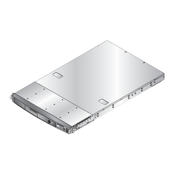
Chapter 1 Introduction The SGI Altix XE320 server is a 1U rackmount server (refer to Figure 1-1) that contains two node boards in a single chassis. Each node supports two Intel ® Xeon ® dual- or quad-core processors. s g i... - Page 30 1: Introduction In addition to the node and chassis, the following hardware components are included (refer to Figure 1-2): • One or two dual-core or quad-core processors per node board • Two processor heatsinks per node board • Four hard drive carriers (two per node) •...
-
Page 31: Figure 1-2 Chassis Components
PCIe riser card PCIe card IPMI 2.0 BMC DIMMs Power supply SATA disk drive cables PCIe riser card Intel Xeon PCIe card processor heatsink Node board 1 Fans IPMI 2.0 BMC DIMMs SATA disk drive cables Node board 2 Node board 2 power connectors SATA backplane SATA connections SATA disk drives... -
Page 32: Node Board Features
1: Introduction Node Board Features At the heart of the SGI Altix XE320 lies two dual-processor node boards, which are based on the Intel 5400P chipset (refer to Figure 1-3). Below are the main features of the node board. Note: The features on each node board are doubled for the server (refer to Appendix D, “System Specifications”). -
Page 33: Figure 1-3 Node Board Block Diagram
Node Board Features PROCESSOR#2 PROCESSOR#1 1333/1600 1333/1600 MT/S MT/S PCI-EXP x16 FBD CHNL0 Intel 5400 FBD CHNL1 FBD CHNL2 FBD CHNL3 PCI-EXP x8 MT25204 ESB2 3.0 Gb/S USB 2.0 PCI 33MHz CONN ES1000 GB LAN RJ45 W83627 GILGAL RJ45 COM2 Figure 1-3 Node Board Block Diagram 007-5466-001... -
Page 34: Serial Attached Scsi (Sas) And Raid Support
Ethernet LAN (NIC) ports, and one optional InfiniBand ® port. ATI Graphics Controller The SGI Altix XE320 features an integrated ATI video controller based on the ES1000 graphics chip. The ES1000 was designed specifically for servers, featuring low-power consumption, high reliability, and superior longevity. Other Features... -
Page 35: Server Chassis Features
Server Chassis Features Server Chassis Features This section describes the main features of the SGI Altix XE320 1U chassis. Refer to Chapter 5, “Advanced Chassis Setup.” for more detailed information. Note: For more detail on the chassis, refer to Chapter 5, “Advanced Chassis Setup.”... -
Page 36: Rear I/O Panel
Rear I/O Panel The I/O panel provides slots for two low-profile PCI-Express 2.0 x16 expansion cards, two COM ports, four USB ports, two VGA ports, and four Gb Ethernet ports. The server also provides two InfiniBand ports. Cooling System The server chassis has an innovative cooling design that features two sets of triple (for a total of six) 4-cm high-performance fans. -
Page 37: Server Installation
This chapter provides a quick setup checklist to get the SGI Altix XE320 operational. Unpack the System Inspect the shipping container that the SGI Altix XE320 was shipped in and note if it was damaged in any way. If the server shows damage, file a damage claim with the carrier who delivered it. -
Page 38: Warnings And Precautions
Rack Precautions Warning: The SGI Altix XE320 server weighs 40 lb (18 kg). Always use proper lifting techniques when your move the server. Always get the assistance of another qualified person when you install the sever in a location above your shoulders. Failure to do so may result in serious personal injury or damage to the equipment. -
Page 39: Server Precautions
Rack Mounting Considerations Server Precautions • Review the electrical and general safety precautions in Appendix E, “System Safety.” • Determine the placement of each component in the rack before you install the rails. • Install the heaviest server components in the bottom of the rack first, and then work up. •... -
Page 40: Circuit Overloading
Install the System into a Rack This section provides information on installing the SGI Altix XE320 into a rack unit with the rack rails provided. If the system has already been mounted into a rack, refer to “Check the Node Board Setup”... -
Page 41: Install The Rails
Install the System into a Rack Install the Rails Perform the following procedure to install the inner rails: If the left and right side inner rails (refer to Figure 2-1) have not been pre-attached to the chassis, attach them. Outer rail (attaches to rack) Inner rail (pre-installed) Locking tab Figure 2-1... -
Page 42: Figure 2-3 Attaching The Inner Bracket
2: Server Installation Install two screws to attach the inner bracket to the front of the rail. (Refer to Figure 2-3.) Figure 2-3 Attaching the Inner Bracket 4. Attach the rail to the front of the rack chassis (refer to Figure 2-4): Slide the front brackets over the appropriate holes in the rack frame. -
Page 43: Figure 2-4 Attaching The Rail To The Front Of The Rack (View From Front Of Rack)
Install the System into a Rack Attach these two screws. The sheet metal from the rack frame fits between the two brackets on the front of the rail. Figure 2-4 Attaching the Rail to the Front of the Rack (View from Front of Rack) 5. -
Page 44: Locking Tabs
Install the Server in a Rack Warning: The SGI Altix XE320 server weighs 40 lb (18 kg). Always use proper lifting techniques when your move the server. Always get the assistance of another qualified person when you install the sever in a location above your shoulders. Failure to do so may result in serious personal injury or damage to the equipment. -
Page 45: Figure 2-6 Install The Server In A Rack
Install the System into a Rack Figure 2-6 Install the Server in a Rack 007-5466-001... -
Page 46: Install The Server In A Third-Party Rack
Install the Server in a Third-party Rack Warning: The SGI Altix XE320 server weighs 40 lb (18 kg). Always use proper lifting techniques when your move the server. Always get the assistance of another qualified person when you install the sever in a location above your shoulders. Failure to do so may result in serious personal injury or damage to the equipment. - Page 47 Install the System into a Rack 2. Using three screws each, attach the outer rail assembly onto the right angle brackets. Figure 2-8 Install the Server in a Third-party Rack (2) 007-5466-001...
- Page 48 2: Server Installation 3. Install the right angle brackets onto the two-post rack, using two screws on each end. Figure 2-9 Install the Server in a Third-party Rack (3) 007-5466-001...
-
Page 49: Check The Node Board Setup
Check the Node Board Setup Check the Node Board Setup Use the following sections to open the top cover and check that each node board is properly installed and all the connections have been made. Access the Inside of the Chassis Refer to Figure 2-10 when using the following procedure. -
Page 50: Check The Cpus (Processors)
2: Server Installation Figure 2-10 Remove the Top Cover Check the CPUs (processors) You may have one or two processors installed on each node board. Each processor needs its own heatsink. Refer to Chapter 4, “Advanced Node Board Setup,” for instructions on how to install processors and heatsinks. -
Page 51: Install Expansion Pcie Cards
(PDU). The PDU offers protection from electrical noise and power surges. SGI also recommends that you use an uninterruptible power supply (UPS) source. -
Page 53: Controls And Indicators
This chapter describes the functions of the controls and indicators (light emitting diodes, or LEDs) on the SGI Altix XE320 server. There are several LEDs on the two control panels (refer to Figure 3-1) as well as others on the drive carriers that inform you of the overall system status, as well as the activity and status of specific components. -
Page 54: Indicators
Front Panel Controls and Indicators Indicators Each control panel is located on the front of the SGI Altix XE320 system and has five LED indicators (refer to Figure 3-1). Each LED provides you with critical information related to its own specific node board. -
Page 55: Drive Carrier Indicators
Indicators Note: Check the routing of the cables and make sure all fans are present and operating normally. Check that the chassis covers are installed properly. Verify that the processor heatsinks are installed properly (refer to Chapter 4). Verify that the overhead/fan fail LED remains flashing. -
Page 57: Advanced Node Board Setup
Chapter 4 Advanced Node Board Setup This chapter includes procedures to install a node board into the SGI Altix XE320 chassis, connect the data and power cables, and install expansion cards. All node board jumpers and connections are also discussed. -
Page 58: Esd Precautions
Caution: The node board is shipped in antistatic packaging to avoid electrostatic discharge damage. Be sure to use ESD precautions when you unpack replacement components for the SGI Altix XE320 server. Failure to do so can result in damage to the equipment. -
Page 59: Node Board Installation
Node Board Installation Node Board Installation This section explains how to mount the node board into the SGI Altix XE320 chassis. To remove the node board, follow this procedure in reverse order. Access the inside of the system (refer to Figure 4-1): Remove the rack rails so that you can gain access to the top cover screws. -
Page 60: Connect The Power Cables
2. Check compatibility of node board ports and I/O shield: Note: Make sure that the I/O ports on the node boards align properly with their respective holes in the I/O shield on the back of the SGI Altix XE320 chassis. 3. Remove the PCI card riser card and bracket. -
Page 61: Figure 4-2 Node Board Installation
Node Board Installation For node board 2 (installed on the right side of the chassis): Connect the power cable to the secondary ATX power header on the left side of the node board. 2. Connect the auxiliary power cable to the power connector on right side of the SATA backplane. -
Page 62: Connecting The Control Panel
4: Advanced Node Board Setup Connecting the Control Panel The JF1 connector (refer to Figure 4-3) contains header pins for various front control panel connectors, switches, and LED indicators. All of the JF1 connector wires are bundled into a single ribbon cable to simplify this connection. Make sure the red wire plugs into pin 1 as marked on the board. -
Page 63: I/O Ports
I/O Ports I/O Ports The I/O ports are color coded. Figure 4-4 shows the color and location of the various I/O ports on the I/O panel. USB 0/1 Ports LAN 1 LAN 2 COM2 Port InfiniBand Port VGA Port (Turquiose) (Blue) Figure 4-4 I/O Port Locations... -
Page 64: Install A Processor
4: Advanced Node Board Setup Note: SGI’s replacement Xeon CPU package contains a heatsink assembly. Make sure that the black pick-and-place (PnP) cap is in place; otherwise, contact the SGI immediately. Important!: When you install only a single CPU on each node board, install the single CPU in socket 2 (refer to Figure 4-11 on page 58) on both node boards. - Page 65 Processor and Heatsink Installation and Removal 2. Gently lift the load lever to open the load plate. Load plate released 3. Use your thumb and your index finger to hold the CPU at opposite sides. 007-5466-001...
- Page 66 4: Advanced Node Board Setup 4. Align pin 1 of the CPU (the corner marked with a triangle) with the notched corner of the CPU socket. Caution: In step 5, do not drop the CPU on the socket. Do not move the CPU horizontally or vertically, and do not rub the CPU against any surface or any of the contacts which may damage the CPU and/or contacts.
- Page 67 Processor and Heatsink Installation and Removal 8. Use your thumb to gently push the load lever down until it snaps into the retention clasp. Load lever 9. If the CPU is properly installed into the socket, the PnP cap is automatically released from the load plate when the lever locks.
-
Page 68: Install A Heatsink
4: Advanced Node Board Setup 10. Remove the PnP cap. PnP cap released from load plate 11. Repeat these steps to install a second CPU if desired. Install a Heatsink Ensure that you have replaced the thermal interface material (TIM) between the heatsink and the CPU die. -
Page 69: Remove The Heatsink
Install a CPU Heatsink Remove the Heatsink SGI does not recommend that the CPU or the heatsink be removed from the node board. However, if you do need to remove the heatsink, use the instructions below to prevent damage to the CPU or the CPU socket. -
Page 70: Replace The Thermal Interface Material
4: Advanced Node Board Setup 5. Apply a small amount of thermal interface material (TIM) on the surface of the CPU before you install the heatsink. Replace the Thermal Interface Material The Intel Xeon processors used in your server require a thermal interface material (TIM) between the processors and heatsinks to properly dissipate the heat that is generated by the processors. - Page 71 Processor and Heatsink Installation and Removal Perform the following steps to remove the TIM from a processor: Remove the heatsink from the socket. Note: If you plan to re-use the heatsink with a replacement processor, you must clean the TIM off of the heatsink. (Refer to “Removing TIM from a Heatsink” on page 46.) 2.
- Page 72 4: Advanced Node Board Setup 3. Use a dry lint-free cloth to lift the loose TIM pieces off of the processor. 007-5466-001...
- Page 73 Processor and Heatsink Installation and Removal 4. Use a dry, lint-free cloth to wipe any remaining TIM pieces off of the processor. 5. Use a different lint-free cloth moistened with isopropyl alcohol (IPA) to remove any remaining TIM from the processor. 007-5466-001...
-
Page 74: Removing Tim From A Heatsink
4: Advanced Node Board Setup Note: Be sure to remove TIM from the gaps between the processor and the load plate. Removing TIM from a Heatsink If you plan re-use the heatsink with a replacement processor, you need to remove the TIM from the heatsink. - Page 75 Processor and Heatsink Installation and Removal 2. Use a dry, lint-free cloth to wipe any loose TIM pieces off of the heatsink. 007-5466-001...
-
Page 76: Remove The Processor
4: Advanced Node Board Setup Use a different lint-free cloth moistened with isopropyl alcohol (IPA) to remove any remaining TIM from the heatsink. Remove the Processor Press the load lever down and away from the retention clasp to release the load plate from its locked position. - Page 77 3. Use your thumb and your index finger to hold the CPU at opposite sides. 4. Carefully lift the CPU straight out of the socket. Note: If you are removing the porcessor so that you can return the node board to SGI, install a PnP cap in the socket.
-
Page 78: Install Memory
4: Advanced Node Board Setup Install Memory Caution: Exercise extreme care when installing or removing DIMM modules to prevent damage to the node board or DIMM module. The node board provides eight 240-pin DIMM sockets that can support up to 64 GB of error correction code (ECC) fully buffered DIMM (FBDIMM) DDR2-800/667 SDRAM (for a total of 128 GB in the system). -
Page 79: Constraints For Dimm Pairs
Install Memory DIMM 1B DIMM 2B DIMM 3B DIMM 4B DIMM 1A DIMM 2A DIMM 3A DIMM 4A Bank 1 Bank 2 Bank 3 Bank 4 Branch 0 Branch 1 Memory Controller Hub (MCH) Figure 4-6 Minimum Population for Dual-Channel Mode with Identical FBDIMMs Constraints for DIMM Pairs The DIMM pairs (1A,2A), (3A,4A), (1B,2B), and (3B,4B) must be identical with respect to the following attributes:... -
Page 80: Performance Optimization
4: Advanced Node Board Setup Performance Optimization The primary rule for installing DIMMs to obtain maximum performance is the following: Balance the DIMM memory capacity across both memory branches. As illustrated in Figure 4-6, the MCH has memory Branch 0 and Branch 1. DIMMs 1A, 1B, 2A, and 2B are on Branch 0 and DIMMs 3A, 3B, 4A, and 4B are on Branch 1. -
Page 81: Memory Sparing Mode
Install Memory • Single DIMM pair • Three DIMM pairs all having the same memory capacity Memory Sparing Mode To select memory sparing mode, you must select sparing in the BIOS setup: Advanced --> Advanced Chipset Control Figure 4-7 illustrates the standard DIMM population for sparing mode. Branch 0 Branch 1 Mirroring... -
Page 82: Mirroring Mode Upgrade
4: Advanced Node Board Setup Configure memory mirroring with the Memory Branch Mode BIOS setting (refer to “Memory Branch Mode” on page 114. Figure 4-7 illustrates the standard DIMM population for mirroring mode. The minimum number of DIMM supported in mirror mode is four. All four DIMMs must be identical in size, speed, and organization. -
Page 83: Figure 4-8 Install Dimms
Install Memory Release Note: Align notch in Release DIMM with notch in DIMM slot Top View of DIMM Slot Figure 4-8 Install DIMMs Table 4-2 lists the order in which you should install DIMMs to optimize your memory configuration. Figure 4-11 shows the DIMM slot designations and bank locations on the node board. -
Page 84: Figure 4-9 Replace Dimms
4: Advanced Node Board Setup Figure 4-9 Replace DIMMs 007-5466-001... -
Page 85: Install Or Remove The Air Shroud
Install or Remove the Air Shroud Install or Remove the Air Shroud Position each air shrouds as shown in Figure 4-10. 2. Gently place the air shrouds over the node boards and just over the fan assemblies. 3. Slide the air shroud towards the rear of the chassis. 4. -
Page 86: Node Board Component Locations
4: Advanced Node Board Setup Node Board Component Locations InfiniBand COM2 BIOS Speaker ES1000 JPG1 JWOL Battery JBT1 JWOR JI2C1 JI2C1 SGPIO JPL1 JPL2 South Bridge ESB2 JUSB2 North Bridge 5400P CPU2 CPU1 Secondary Primary ATX power header ATX power header Figure 4-11 Node Board Component Locations 007-5466-001... -
Page 87: Add Pcie Expansion Cards
Add PCIe Expansion Cards Add PCIe Expansion Cards The SGI Altix XE320 includes two preinstalled riser boards in the 1U rackmount chassis (refer to Figure 4-12). These riser cards support two low-profile PCI Express 2.0 x16 cards. Note: Use only SGI approved PCI Express 2.0 x16 cards in the SGI Altix XE320 server. -
Page 88: Figure 4-12 Install A Pci Card
4: Advanced Node Board Setup PCI riser board Bracket PCI expansion card Figure 4-12 Install a PCI Card 007-5466-001... -
Page 89: Node Board Jumpers And Connectors
Node Board Jumpers and Connectors Node Board Jumpers and Connectors Refer to Figure 4-11 when using Table 4-3, Table 4-4 and Table 4-5. Table 4-3 Node Board Default Jumper Settings Jumper Description Default Setting JBT1 CMOS Clear Refer to “CMOS Memory Clear (JBT1)”... -
Page 90: Table 4-5 Node Board Led Descriptions
4: Advanced Node Board Setup Table 4-4 Node Board Connector Descriptions (continued) Connector Description JP10 4-pin Auxiliary Power Connector (for HDDs) JWOL Wake-on-LAN Connector JWOR Wake-on-Ring Connector LAN1/2 Gigabit Ethernet Ports SATA0 – SATA3 Intel SATA 0 – 3 Ports SGPIO Serial ATA General Purpose Input/Output Connector SIMSO IPMI... -
Page 91: Node Board Connector Pin Definitions
Node Board Connector Pin Definitions Node Board Connector Pin Definitions Use Table 4-6 to locate the page number for the node board connector or jumper. Table 4-6 Node Board Connector Pin Definitions Connector Description Page Connector Name Page ATX Power Connector Pin Definitions page 64 ATX Power 1/2 page 64... -
Page 92: Atx Power Connector Pin Definitions
4: Advanced Node Board Setup ATX Power Connector Pin Definitions Table 4-7 ATX Power Connector Pin Definitions ATX Power 20-pin Connector Pin Definitions ATX Power 1/2 Notes Pin# Definition Pin# Definition The main ATX power supply connectors on the node PS On Ground board meet the SSI (Superset ATX) 24-pin specification. -
Page 93: Pw_On Switch Pin Definitions (Jf1)
Node Board Connector Pin Definitions PW_ON Switch Pin Definitions (JF1) Table 4-9 PW_ON Switch Pin Definitions (JF1) PW_ON Button Pin Definitions Notes Pin# Definition The PW_ON connector is on pins 1 and 2 of JF1 (refer to PW_ON Figure 4-16 on page 78). This header should be connected to the Ground chassis power button. -
Page 94: Nic2 Led Pin Definitions (Jf1)
4: Advanced Node Board Setup NIC2 LED Pin Definitions (JF1) Table 4-12 NIC2 LED Pin Definitions (JF1) NIC2 LED Pin Definitions Notes Pin# Definition The NIC2 LED connection (LAN2) is on pins 9 and 10 of JF1 (refer to Figure 4-16 on page 78) and displays network activity on Ground LAN 2. -
Page 95: Power On Led Pin Definitions (Jf1)
Node Board Connector Pin Definitions Power On LED Pin Definitions (JF1) Table 4-15 Power On LED Pin Definitions (JF1) Power On LED Pin Definitions Notes Pin# Definition The Power On LED connector is located on pins 15 and 16 of JF1. 5V Standby Use this connection is used to indicate that power is supplied to Control... -
Page 96: Fan Connector Pin Definitions (Fan1/2 - Fan7/8)
Chassis Intrusion Pin Definitions (JL1) Chassis Intrusion Pin Definitions Notes Pin# Definition The Chassis Intrusion connector is designated JL1 (refer to Intrusion Input Figure 4-15 on page 77). Note: The feature is not supported on Ground the SGI Altix XE320 server. 007-5466-001... -
Page 97: Usb Connector Pin Definitions (Usb0/Usb1)
Node Board Connector Pin Definitions USB Connector Pin Definitions (USB0/USB1) Table 4-19 Universal Serial Bus (USB) Pin Definitions USB Ports USB0/1 Notes Pin# Definition There are two Universal Serial Bus ports located on the I/O panel and two additional USB headers located on the node board. The headers, labeled USB2 and USB3, can be used to provide front side USB access (cables not included). -
Page 98: Ethernet Port (Lan1/Lan2)
4: Advanced Node Board Setup Ethernet Port (LAN1/LAN2) Table 4-20 Ethernet Ports (LAN1/LAN2) Ethernet Ports Notes LAN1/LAN2 Two gigabit Ethernet ports (designated LAN1 and LAN2) are located on the I/O panel. These ports accept RJ45 type cables. Wake on LAN Connector Pin Definitions (JWOL) Table 4-21 Wake on LAN Connector Pin Definitions (JWOL) Wake-On-LAN Pin Definitions... -
Page 99: Serial Port Pin Definitions (Com2)
Node Board Connector Pin Definitions Serial Port Pin Definitions (COM2) Table 4-23 Serial Port Pin Definitions (COM2) Serial Port Pin Definitions COM2 Notes Pin# Definition Pin# Definition One serial port is included on the node board: COM2 is a port located beside the VGA port. Ground Serial General Purpose I/O Connector Pin Definitions (SGPIO) Table 4-24... -
Page 100: System Management Bus Power Connector Pin Definitions (J17)
4: Advanced Node Board Setup System Management Bus Power Connector Pin Definitions (J17) Table 4-25 SMB Power Connector Pin Definitions (J17) SMB Power (I C) Pin Definitions Notes Pin# Definition The system management bus (SMB) power connector (J17) is used Clock to support the I2C bus. -
Page 101: Node Board Jumper Settings
Node Board Jumper Settings Node Board Jumper Settings Table 4-27 Node Board Jumper Descriptions Connector Description Page Jumper Name Page CMOS Memory Clear (JBT1) page 75 JBT1 page 75 I2C to PCIe Slot Jumper Settings (JPI2C1/JPI2C2) page 76 JPG1 page 76 LAN1/LAN2 Jumper Settings (JPL1/JPL2) page 77 JPI2C1/JPI2C2... -
Page 102: Explanation Of Jumper Settings
4: Advanced Node Board Setup Explanation of Jumper Settings To modify the operation of the node board, jumpers (refer to Figure 4-13) can be used to choose between optional settings. Jumpers create shorts between two pins to change specific functions or features on the node board. -
Page 103: Cmos Memory Clear (Jbt1)
Node Board Jumper Settings CMOS Memory Clear (JBT1) Jumper pad JBT1 (refer to Figure 4-14) is used to clear CMOS memory (which also clears passwords). Instead of pins, this jumper consists of contact pads to prevent you from accidentally clearing the contents of CMOS memory. To clear CMOS memory: Power down the system and unplug the power cord(s). -
Page 104: Vga Jumper Settings (Jpg1)
4: Advanced Node Board Setup VGA Jumper Settings (JPG1) Table 4-28 VGA Jumper Settings (JPG1) VGA Enable/Disable Jumper Settings JPG1 Notes Jumper Definition Jumper JPG1 (refer to Figure 4-14) enables or disables the Enabled VGA port. The default position is pins 1 and 2 jumpered, which Disabled enables VGA port. -
Page 105: Lan1/Lan2 Jumper Settings (Jpl1/Jpl2)
Node Board Jumper Settings LAN1/LAN2 Jumper Settings (JPL1/JPL2) Table 4-30 LAN1/LAN2 Jumper Settings (JPL1/JPL2) LAN1/LAN2 Enable/Disable Jumper Settings JPL1/JPL2 Notes Jumper Definition Jumper JPL1 (refer to Figure 4-15) enables or disables the Enabled LAN1 port and JPL2 to enable or disable the LAN2 port on the Disabled node board. -
Page 106: Watch Dog Timer Jumper Settings (Jwd)
4: Advanced Node Board Setup Watch Dog Timer Jumper Settings (JWD) Users must write their own application software to disable the watch dog timer when it is enabled. Table 4-31 Watch Dog Timer Jumper Settings (JWD) Watch Dog Jumper Settings Notes Jumper Definition... -
Page 107: Node Board Led Descriptions
Node Board LED Descriptions Node Board LED Descriptions LAN1 and LAN2 (Ethernet Ports) Table 4-32 LAN1 and LAN 2 LED Descriptions LAN LED Speed Indicators LAN1/LAN2 Notes LED Color Description The Ethernet ports (located beside the serial COM2 port) 10 MHz have two LEDs. -
Page 108: Figure 4-17 Infiniband Link Led Location (Le1)
4: Advanced Node Board Setup InfiniBand COM2 LE3 LE2 BIOS Speaker ES1000 JPG1 JWOL Battery JBT1 JWOR SGPIO JPL1 JPL2 South Bridge ESB2 JUSB2 North Bridge 5000P CPU2 CPU1 Secondary Primary ATX Power ATX Power Header Header CPU1 Figure 4-17 InfiniBand Link LED Location (LE1) 007-5466-001... -
Page 109: Infiniband Link/Activity Leds (Le2/Le3)
Node Board LED Descriptions InfiniBand Link/Activity LEDs (LE2/LE3) Table 4-34 InfiniBand Link/Activity LED Descriptions (LE2/LE3) InfiniBand Link/Activity LEDs LE2/LE3 Notes LED Color Description Two InfiniBand LED Indicators (LE2/LE3) are LE2 Green (solid) InfiniBand connected located near the InfiniBand connector (refer to LE2 (Off) No connection Figure 4-18). -
Page 111: Advanced Chassis Setup
Advanced Chassis Setup This chapter covers the steps required to install components and perform maintenance on the SGI Altix XE320 chassis (refer to Figure 5-1 and Figure 5-2). ESD Precautions Electrostatic Discharge (ESD) can damage electronic components. To prevent damage to any printed circuit boards (PCBs), it is important to handle them very carefully. -
Page 112: Chassis Components
5: Advanced Chassis Setup Chassis Components Control panel: Node board 1 Control panel: Node board 2 SATA drives Figure 5-1 Chassis Front View Power supply PCIe x16 slot PCIe x16 slot InfiniBand port USB ports COM2 port InfiniBand port USB ports COM2 port LAN ports VGA port... -
Page 113: Control Panel
Control Panel Control Panel Each control panel on the front of the chassis must be connected to the JF1 connector on its associated node board to provide you with system control buttons and status indicators. When viewed from the front of the chassis, the node board on the left is referred to as node board 1 and the node board on the right is node board 2. -
Page 114: Part Numbers And Marketing Codes
5: Advanced Chassis Setup Part Numbers and Marketing Codes Table 5-1 lists the marketing codes and part numbers for the SGI Altix XE320 server. Table 5-1 Part Numbers and Marketing Codes Description SGI Part number/Marketing Code 1U base chassis (GigE on-board) with two compute nodes... -
Page 115: System Fans
Each node board has its own set of three 4-cm high-performance fans (for a total of six in the chassis) to provide the cooling for the SGI Altix XE320. The fan speed can be controlled by a setting in BIOS. Refer to Chapter 6, “BIOS Settings” for more information. -
Page 116: Disk Drive Installation
5: Advanced Chassis Setup Caution: Use caution when working with the SATA/SAS backplane. Do not touch the backplane with any metal objects, and make sure that ribbon cables do not touch the backplane. Also, regardless of how many drives are installed, all four drive carriers must remain in the chassis to maintain proper airflow. -
Page 117: Drive Replacement
Disk Drive Replacement Drive Replacement The drive carriers are all easily accessible at the front of the chassis. These are (with RAID enabled) hot-swap drives. To remove a carrier, push the release button located beside the drive LEDs. Then, swing the handle fully out and use it to pull the unit straight out (refer to Figure 5-5). Figure 5-5 Drive Removal 007-5466-001... -
Page 118: Power Supply
5: Advanced Chassis Setup Power Supply The SGI Altix XE320 has a single 980 watt power supply. This power supply has the capability of operating at 100 - 240 input volts. Depress both main power buttons on the front of the chassis and then unplug the AC power cord to completely remove power from the system before removing the power supply. -
Page 119: Figure 5-6 Power Supply Replacement
Power Supply Power supply Lever Figure 5-6 Power Supply Replacement 007-5466-001... -
Page 121: Bios Settings
Chapter 6 BIOS Settings This chapter lists the BIOS default settings and describes the setup utility for the node board. The BIOS is stored in a flash chip and can be easily upgraded. For the upgrade procedure, see Appendix G, “Upgrading BIOS”. Note: Due to periodic changes to the BIOS, some settings may have been added or deleted and might not yet be recorded in this manual. -
Page 122: Table 6-1 Bios Default Settings
6: BIOS Settings Table 6-1 BIOS Default Settings (continued) Menu Item Setting Page Serial ATA [Enabled] Native Mode Operation [Serial ATA] SATA Controller Mode Option [Enhanced] SATA RAID [Disabled] SATA AHCI [Enabled] System Memory 634 KB varies Extended Memory 2047 MB ( MAIN / SATA Port Type [Auto]... - Page 123 Default Settings Table 6-1 BIOS Default Settings (continued) Menu Item Setting Page Summary screen [Enabled] Advanced / Memory Cache Cache System BIOS area [Write Protect] Cache Video BIOS area [Write Protect] Cache Base 0-512k [Write Back] Cache Base 512k-640k [Write Back] Cache Extended Memory Area [Write Back] Discrete MTRR Allocation...
- Page 124 6: BIOS Settings Table 6-1 BIOS Default Settings (continued) Menu Item Setting Page Enable Master [Enabled] Latency Timer [Default] Advanced /Advanced Chipset Control SERR signal condition [both] Intel VT for directed I/O (vt-d) Disabled] 4GB PCI Hole Granularity [256 MB] Memory voltage [auto] Memory Branch Mode...
- Page 125 Default Settings Table 6-1 BIOS Default Settings (continued) Menu Item Setting Page Patrol Scrub [Enabled] High Precision Event Timer [Yes] USB Function [Enabled] Legacy USB Support [Enabled] Advanced / Advanced Processor Options varies CPU Speed 2.33 GHz ( Frequency Ratio [Default] Core Multi-Processing [Enabled]...
- Page 126 6: BIOS Settings Table 6-1 BIOS Default Settings (continued) Menu Item Setting Page Serial port B [Enabled] Mode [Normal] Base I/O address [2F8] Interrupt [IRQ 3] Advanced / DMI Event Logging Event log validity Valid Event log capacity Space Available View DMI event log [Enter] Event Logging...
- Page 127 Default Settings Table 6-1 BIOS Default Settings (continued) Menu Item Setting Page FAN1 = 10629 RPM FAN2 = 9060 RPM FAN3 = 10546 RPM FAN4 = 9375 RPM FAN5 = 10975 RPM FAN6 = 9000 RPM FAN7 = FAN8 = Fan Speed Control Modes [1) disable (full speed)] VcoreA...
- Page 128 6: BIOS Settings Table 6-1 BIOS Default Settings (continued) Menu Item Setting Page SYS Firmware Progress [Disabled] BIOS POST Errors [Enabled] BIOS POST Watchdog [Disabled] OS boot Watchdog [Disabled] Timer for loading OS (min) [10] Time out action [No Action] >...
- Page 129 Default Settings Table 6-1 BIOS Default Settings (continued) Menu Item Setting Page : IDE 0: : IDE 1: : IDE 4: : IDE 5: : USB HDD: : PCI SCSI: HDT722525DLA380-(S0) : PCI SCSI: HDS725050KLA360-(S1) (If installed) : USB ZIP: : USB LS120: : PCI BEV: IBA GE Slot 0400 v1236...
-
Page 130: System Bios
6: BIOS Settings System BIOS The BIOS is the Basic Input Output System used in nearly all computers. The BIOS stores the system parameters, types of disk drives, video displays, etc. in the CMOS. The CMOS memory requires very little electrical power. When the computer is turned off, a backup battery provides power to the CMOS logic, enabling it to retain system parameters. -
Page 131: Running Setup
Running Setup Running Setup The BIOS setup options described in this section are selected by choosing the appropriate text from the main BIOS Setup screen. All displayed text is described in this section, although the screen display is often all you need to understand how to set the options. When you first power on the computer, the BIOS is immediately activated. -
Page 132: Main Bios Setup
6: BIOS Settings Main BIOS Setup The main BIOS Setup screen is displayed in Figure 6-1. All main setup options are described in this section. • Use the Up/Down arrow keys to move among the different settings in each menu. •... -
Page 133: Main Setup Features
Main BIOS Setup Main Setup Features System Time To set the system date and time, type the correct information into the appropriate fields. Then, press the <Enter> key to save the data. System Date Using the arrow keys, highlight the month, day, and year fields, and enter the correct data. Press the <Enter>... -
Page 134: Serial Ata Ports
6: BIOS Settings Serial ATA Ports These settings allow the user to set the parameters of the SATA ports. Press <Enter> to activate the following submenu screen for detailed options of these items. Set the correct configurations accordingly. Type This option enables you to select the type of IDE hard drive. The option Auto enables the BIOS to automatically configure the parameters of the hard disk drive (HDD) installed at the connection. -
Page 135: Multi-Sector Transfers
Main BIOS Setup Multi-Sector Transfers This item enables you to specify the number of sectors per block to be used in multi-sector transfer. The options are Disabled, 4 Sectors, 8 Sectors, and 16 Sectors. LBA Mode Control This item determines whether the BIOS accesses the IDE Channel 0 Master Device via the LBA mode. -
Page 136: Serial Ata (Sata) Raid Enable
When the SATA Controller Mode is set to Enhanced, the following items are displayed. Note: The SATA RAID functions were not supported when this manual was published. Check with SGI Global Customer Service to verify that the SATA RAID features are fully supported. Serial ATA (SATA) RAID Enable Select Enable to enable Serial ATA RAID functions. -
Page 137: Advanced Setup
Advanced Setup Advanced Setup Choose Advanced from the BIOS Setup Utility main menu with the arrow keys. The items with a triangle beside them have submenus that can be accessed by highlighting the item and pressing <Enter>. Boot Features Access the submenu to make changes to the following settings. QuickBoot Mode If enabled, this feature speeds up the POST routine by skipping certain tests after the computer is turned on. -
Page 138: Post Errors
6: BIOS Settings POST Errors Set to Enabled to display POST Error Messages if an error occurs during bootup. If set to Disabled, the system will continue to boot without displaying any error message even when a boot error occurs. ACPI Mode Use this setting to determine if you want to employ ACPI (Advanced Configuration and Power Interface) power management on your system. -
Page 139: Memory Cache
Advanced Setup Memory Cache Cache System BIOS Area This setting enables you to designate a reserve area in the system memory to be used as a System BIOS buffer to allow BIOS to write (cache) its data into it. Select Write Protect to enable the function and reserve this area for system BIOS ROM access only. -
Page 140: Pcie Configuration
6: BIOS Settings from the buffer without writing data to the system memory to speed up CPU’s operation. The options are Uncached, Write Through, Write Protect and Write Back. PCIe Configuration Access the submenu to make changes to the following settings for PCIe devices. Onboard GLAN1/Onboard GLAN2 (Gigabit- LAN) OPROM Configure Enabling this option provides the capability to boot from GLAN Port 1 or GLAN Port 2. -
Page 141: Reset Configuration Data
Advanced Setup Reset Configuration Data If set to Yes, this setting clears the Extended System Configuration Data- (ESCD) area. The options are Yes and No. Slot1 PCIe x8 Access the submenu for each of the settings above to make changes to the following: Option ROM Scan When enabled, this setting will initialize the device expansion ROM. -
Page 142: Serr Signal Condition
6: BIOS Settings Caution: Use caution when changing the Advanced settings. Incorrect values entered may cause a system to malfunction. Also, a very high DRAM frequency or incorrect DRAM timing may cause system to become unstable. When this occurs, revert the item to the default setting. SERR Signal Condition This setting specifies the ECC Error conditions. -
Page 143: High Bandwidth Fsb
Advanced Setup High Bandwidth FSB The front side bus (FSB) is the physical bi-directional data bus that carries signals between the central processing unit (CPU) and other devices within the system, such as random access memory (RAM), AGP video cards, PCI expansion cards, hard disks, the memory containing the system BIOS, etc. -
Page 144: Crystal Beach Features
6: BIOS Settings Crystal Beach Features This feature was designed to implement Intel’s I/O AT (Acceleration Technology) to accelerate the performance of TCP offload engine (TOE) devices. Note: A TOE device is a specialized, dedicated processor that is installed on an add-on card or a network card to handle some or all packet processing of the add-on card. -
Page 145: Advanced Processor Options
Advanced Setup Advanced Processor Options CPU Speed This is a display that indicates the speed of the installed processor. Frequency Ratio This feature enables you to set the internal frequency multiplier for the CPU. The options are: Default, x12, x13, x14, x15, x16, x17 and x18. Core-Multi-Processing Set to Enabled to use a processor's second core and beyond. -
Page 146: Execute Disable Bit
6: BIOS Settings Execute Disable Bit Set to Enabled to enable Execute Disable Bit and allow the processor to classify areas in memory where an application code can be executed and where it cannot, and thus preventing a worm or a virus from inserting and creating a flood of codes to overwhelm the processor or damage the system during an attack. -
Page 147: Intel Eist Support
Advanced Setup Intel EIST Support Select Enabled to use the Enhanced Intel SpeedStep Technology and enable the system to automatically adjust processor voltage and core frequency in an effort to reduce power consumption and heat dissipation. The options are Enabled and Disabled. I/O Device Configuration Access the submenu to make changes to the following settings. -
Page 148: Dmi Event Logging
6: BIOS Settings DMI Event Logging Access the submenu to make changes to the following settings. Event Log Validity This is a display to inform you of the event log validity. It is not a setting. Event Log Capacity This is a display to inform you of the event log capacity. It is not a setting. View DMI Event Log Highlight this item and press <Enter>... -
Page 149: Com Port Address
Advanced Setup COM Port Address This item enables you to specify which COM port to direct the remote console to: Onboard COM A or Onboard COM B. This setting can also be Disabled. BAUD Rate This item enables you to set the BAUD rate for console redirection. The options are 300, 1200, 2400, 9600, 19.2K, 38.4K, 57.6K, and 115.2K. -
Page 150: Cpu Temperature Threshold
6: BIOS Settings CPU Temperature Threshold This option allows the user to set a CPU temperature threshold that will activate the alarm system when the CPU temperature reaches this pre-set temperature threshold. The options are 70 C, 75 C, and 85 Highlight this and press <Enter>... -
Page 151: Ipmi
Advanced Setup • Vbat IPMI IPMI Specification Version This item displays the current IPMI Version. Firmware Version This item displays the current Firmware Version. System Event Logging Select Enabled to enable IPMI Event Logging. When this function is set to Disabled, the system will continue to log events received via system interface. -
Page 152: Clear System Event Logging
6: BIOS Settings Clear System Event Logging Enable this function to force the BIOS to clear the system event logs during the next cold boot. The options are Enabled and Disabled. Existing Event Log Number This item displays the number of the existing event log. Event Log Control System Firmware Progress Enable this function to log POST progress. -
Page 153: System Event Log/System Event Log (List Mode)
Advanced Setup System Event Log/System Event Log (List Mode) These options display the System Event (SEL) Log and System Event (SEL) Log in List Mode. Items include: SEL (System Event Log) Entry Number, SEL Record ID, SEL Record Type, Time Stamp, Generator ID, SEL Message Revision, Sensor Type, Sensor Number, SEL Event Type, Event Description, and SEL Event Data. -
Page 154: Realtime Sensor Data
6: BIOS Settings Realtime Sensor Data This feature display information from motherboard sensors, such as temperatures, fan speeds, and voltages of various components. 007-5466-001... -
Page 155: Security
Security Security Choose Security from the BIOS Setup Utility main menu with the arrow keys. Security setting options are displayed by highlighting the setting using the arrow keys and pressing <Enter>. All Security BIOS settings are described in this section. Supervisor Password Is This displays whether a supervisor password has been entered for the system. -
Page 156: Set Supervisor Password
6: BIOS Settings Set Supervisor Password When the item “Set Supervisor Password” is highlighted, press the <Enter> key. When prompted, type the Supervisor’s password in the dialogue box to set or to change the supervisor’s password, which allows access to the BIOS. Set User Password When the item “Set User Password”... -
Page 157: Boot
Boot Boot Choose Boot from the BIOS Setup Utility main menu with the arrow keys. For details on how to change the order and specs of boot devices, refer to the Item Specific Help window. All Boot BIOS settings are described in this section. Boot list Candidate list Boot Priority Order/Excluded from Boot Orders... -
Page 158: Exit
6: BIOS Settings Exit Choose Exit from the BIOS Setup Utility main menu with the arrow keys. All Exit BIOS settings are described in this section. 007-5466-001... -
Page 159: Exit Saving Changes
Exit Exit Saving Changes Highlight this item and press <Enter> to save any changes you have made and to exit the BIOS Setup utility. Exit Discarding Changes Highlight this item and press <Enter> to exit the BIOS Setup utility without saving any changes you may have made. -
Page 161: Bios Power-On Self Test
Appendix A BIOS Power-on Self Test This appendix lists and describes the BIOS power-on self-test (POST) messages and codes. BIOS POST Messages During POST, the BIOS checks the hardware and software systems for problems. If a problem is found, the BIOS activates an alarm or displays a message. The following is a list of the BIOS messages from the POST sequence. - Page 162 CMOS. The BIOS installed Default Setup Values. If you do not want these values, enter Setup and enter your own values. If the error persists, check the system battery or contact SGI technical support.
- Page 163 System cache error - Cache disabled RAM cache failed and BIOS disabled the cache. On older boards, check the cache jumpers. You may have to replace the cache. Contact SGI customer service. A disabled cache slows system performance considerably. CPU ID: CPU socket number for Multi-Processor error.
- Page 164 A: BIOS Power-on Self Test CD ROM Drive CD ROM drive identified. Entering SETUP... Starting Setup program nnnn Failing Bits: The hex number nnnn is a map of the bits at the RAM address which failed the memory test. Each 1 (one) in the map indicates a failed bit. Refer to “Shadow Ram Failed at offset: nnnn”...
- Page 165 BIOS POST Messages One or more I2O Block Storage Devices were excluded from the Setup Boot Menu There was not enough room in the IPL table to display all installed I2O block-storage devices. Operating system not found Operating system cannot be located on either drive A: or drive C:. Enter Setup and verify that the fixed disk and drive A: are properly identified.
- Page 166 A: BIOS Power-on Self Test System BIOS shadowed System BIOS copied to shadow RAM. nnnn UMB upper limit segment address: Displays the address nnnn of the upper limit of Upper Memory Blocks, indicating released segments of the BIOS which can be reclaimed by a virtual memory manager.
-
Page 167: Bios Post Codes
BIOS POST Codes BIOS POST Codes This section lists the power on self test (POST) codes for the BIOS. The POST codes are divided into two categories: recoverable and terminal. Recoverable POST Errors When a recoverable type of error occurs during POST, the BIOS will display a POST code that describes the problem. - Page 168 A: BIOS Power-on Self Test Table A-1 BIOS Post Codes (continued) POST Code Description Initialize caches to initial POST values Initialize I/O component Initialize the local bus IDE Initialize Power Management Load alternate registers with initial POST values Restore CPU control word during warm boot Reset PCI Bus Mastering devices Initialize keyboard controller 1-2-2-3 BIOS ROM checksum...
- Page 169 BIOS POST Codes Table A-1 BIOS Post Codes (continued) POST Code Description Warm start shut down Shadow system BIOS ROM Auto size cache Advanced configuration of chipset registers Load alternate registers with CMOS values Initialize extended memory for RomPilot (optional) Initialize interrupt vectors POST device initialization 2-1-2-3 Check ROM copyright notice...
- Page 170 A: BIOS Power-on Self Test Table A-1 BIOS Post Codes (continued) POST Code Description Disable CPU cache Test RAM between 512 and 640kB Test extended memory Test extended memory address lines Jump to UserPatch1 Configure advanced cache registers Initialize Multi Processor APIC Enable external and CPU caches Setup System Management Mode (SMM) area Display external L2 cache size...
- Page 171 BIOS POST Codes Table A-1 BIOS Post Codes (continued) POST Code Description Re-initialize onboard I/O ports. Configure Motherboard Configurable Devices (optional) Initialize BIOS Data Area Enable Non-Maskable Interrupts (NMIs) Initialize Extended BIOS Data Area Test and initialize PS/2 mouse Initialize floppy controller Determine number of ATA drives (optional) Initialize hard-disk controllers Initialize local-bus hard-disk controllers...
- Page 172 A: BIOS Power-on Self Test Table A-1 BIOS Post Codes (continued) POST Code Description Initialize typematic rate Erase <ESC> prompt Scan for <ESC> key stroke Enter SETUP Clear Boot flag Check for errors Inform RomPilot about the end of POST (optional) POST done - prepare to boot operating system One short beep before boot Terminate QuietBoot (optional)
- Page 173 BIOS POST Codes Table A-1 BIOS Post Codes (continued) POST Code Description Unhook INT 10h if console redirection enabled Force check (optional) Extended ROM checksum (optional) Reclaim console redirection vector Unknown interrupt Check Intel Branding string Alert Standard Format initialization Late init for IPMI Log error if micro-code not updated properly The following POST codes pertain to the boot block in Flash ROM...
- Page 174 A: BIOS Power-on Self Test Table A-1 BIOS Post Codes (continued) POST Code Description Shadow Boot Block System memory test Initialize interrupt vectors Initialize Run Time Clock Initialize video Initialize System Management Manager Output one beep Clear Huge Segment Boot to Mini DOS Boot to Full DOS If BIOS detects error 2C, 2E, or 30 (base 512K RAM error), it displays an additional word-bitmap (xxxx) indicating the address line or bits that failed.
-
Page 175: Ipmi 2.0 Management Utility
Appendix B IPMI 2.0 Management Utility This section describes the baseboard management controller (BMC) intelligent platform management interface (IPMI) 2.0 management utility. It provides basic overview information for the application that supports remote access (KVM-over-LAN). IPMI defines the protocols used for interfacing with the BMC on the node board. The BMC links to a main processor and other onboard elements using a serial bus. - Page 176 B: IPMI 2.0 Management Utility The BMC card supports the functionality of IPMI Version 2.0. The key features include the following: • Supports IPMI 2.0 • Supports Serial over LAN • Supports KVM over LAN • Supports LAN Alerting-SNMP trap •...
-
Page 177: Network Connection
Network Connection The following system administration functions are available through the BMC interface: • “Remote Control” on page 152 Click on this icon for remote access and management of video console redirection. • “Virtual Media” on page 153 Click on this icon to use virtual remote media devices. •... -
Page 178: Functions Listed On The Home Page
B: IPMI 2.0 Management Utility Functions Listed on the Home Page Figure B-1 BMC Remote Console 007-5466-001... - Page 179 Functions Listed on the Home Page The functions of the icons for this home page are listed below: • Home: Click this icon to return to the Home Page. • Console: Click this icon to open the remote console screen. •...
-
Page 180: Remote Control
B: IPMI 2.0 Management Utility Remote Control Click on the Remote Control icon (refer to Figure B-1) to activate its submenus, such as the KVM console and remote power functions. KVM Console Click on this function to configure keyboard, mouse or video settings for the remote host. Figure B-2 Remote Console Screen 007-5466-001... -
Page 181: Remote Power
Click on the Virtual Media icon on the Home Page to activate its submenus—Floppy Disk, CD-ROM, Drive Redirection and Options. Note: The floppy disk menu is not used in the SGI Altix XE320 system. The BIOS file size exceeds that of a floppy disk image. -
Page 182: Cd-Rom Image
B: IPMI 2.0 Management Utility CD-ROM Image Figure B-3 CD-ROM Image 007-5466-001... - Page 183 Virtual Media Refer to Figure B-3. CD-ROM image: Click on this function key to share data stored in your local CD-ROM drive with other users in the remote host through the Windows Share application via USB. 2. Active Image (Drive1): This window displays the filename of the data currently active in host Drive 1.
-
Page 184: Drive Redirection
B: IPMI 2.0 Management Utility Drive Redirection Figure B-4 Drive Redirection 007-5466-001... - Page 185 Virtual Media Refer to Figure B-4. • Drive Redirection: Click on this function key to make local drives accessible for other users via console redirection. This function enables you to share your local drives (CD-ROM and HDDs) with users in the remote systems. •...
-
Page 186: Virtual Media Options
B: IPMI 2.0 Management Utility Virtual Media Options Figure B-5 Virtual Media Options 007-5466-001... - Page 187 Virtual Media Refer to Figure B-5. • Options: Click on this item to activate the Virtual Media sub-menu. • Virtual Media Options: Use this option to disable or enable USB mass storage in the remote host. Check this box to disable the function of Virtual Media Options to prevent data stored in a local drive from being accessed, or uploaded by the user in the remote host.
-
Page 188: System Health
B: IPMI 2.0 Management Utility System Health Click on the System Health icon on the Home Page to activate its submenus: Chassis Control, Monitor Sensor, System Event Log and Alert settings. Chassis Control Click on this item to access Health Monitoring information on the remote system. Figure B-6 Chassis Control 007-5466-001... - Page 189 System Health Refer to Figure B-6. • Power Is: This indicates if the system is on or off for the remote host. • Power On Counter: If power is on, then the counter indicates the length of time the power has been turned on.
-
Page 190: Monitor Sensors
B: IPMI 2.0 Management Utility Monitor Sensors Click on this item to display the Health Monitoring Information shown in Figure B-7 and Table B-1. Figure B-7 Monitor Sensors 007-5466-001... -
Page 191: Table B-1 Health Monitoring Sensors
System Health Table B-1 Health Monitoring Sensors Temperature Monitoring CPU1 Temperature (Temp A, Temp B) Temp A: CPU1 Core1 Temperature Temp B: CPU1 Core2 Temperature CPU2 Temperature (Temp A, Temp B) Temp A: CPU2 Core1 Temperature Temp B: CPU2 Core2 Temperature System Temperature Voltage Monitoring CPU1 VCore... -
Page 192: System Event Log
B: IPMI 2.0 Management Utility System Event Log Click on this item to display the System Health Event Log for the remote system. Figure B-8 System Event Log 007-5466-001... -
Page 193: Alert Settings
System Health Alert Settings Click on this item to activate the alert settings submenu for the remote system. Figure B-9 Alert Settings 007-5466-001... -
Page 194: User Management
B: IPMI 2.0 Management Utility User Management Click on the User Management icon on the Home Page to activate its submenus: Change Password Change Password, Users & Group and Permissions as needed. Click on this icon to activate the Passwords submenu. Change Password. -
Page 195: Users And Groups
User Management Users and Groups Click on this icon to activate the Users & Groups submenu. • User Management: This window displays the user’s information. • Existing users: Select an existing user for information updates. Once a user is selected, click on the “Lookup”... -
Page 196: Permissions
B: IPMI 2.0 Management Utility Permissions Click on this icon to activate the User/Group Permissions submenu. • Show Permissions for User/Group: Click on the arrow on the right to activate the user/group permissions selection menu. • Update: Click this icon to update permissions information. •... -
Page 197: Kvm Settings
KVM Settings KVM Settings Click on the KVM Settings icon on the Home Page to activate its submenus: User Console Refer to Figure B-10. • User Console: Click on this icon to activate the User Console submenu. • User Selection: This field enables you to decide which group the user belongs to. Click on the arrow on the right to activate the selection menu and highlight the name of the group to select it. -
Page 198: Figure B-10 User Console Settings
B: IPMI 2.0 Management Utility Figure B-10 User Console Settings 007-5466-001... - Page 199 KVM Settings • Color Depth: Click on the arrow on the right to select either 16 bit-high colors or 8 bit-256 colors. The standard color depth is 16 bit-high color. This setting is recommended for compression level 0. For typical desktop interfaces, the setting of 8 bit-256 colors is recommended for faster data transmission.
-
Page 200: Keyboard/Mouse
B: IPMI 2.0 Management Utility • Name: Enter the name of a button enter the box. • More Entries: Click on this icon to create more Button Keys. Keyboard/Mouse Select Keyboard/Mouse to configure the keyboard and mouse settings: Figure B-11 Keyboard/Mouse Settings 007-5466-001... - Page 201 KVM Settings Refer to Figure B-11. • Keyboard Model: Select your keyboard model from the pull-down menu. • Key Release Timeout: Check this box to enable the function of “Key Release Timeout,” which sets the time limit for a key to be pressed by the user. •...
-
Page 202: Device Settings
B: IPMI 2.0 Management Utility Device Settings Click on the Device Settings icon on the Home Page to activate its the device settings menu. Network Click on this function key to activate the Network submenu to configure the network settings. Figure B-12 Network Settings 007-5466-001... - Page 203 Device Settings Refer to Figure B-12. • IP Auto Configuration: Click on the box to activate the selection menu and select a desired item from the list. The options are None, DHCP, and BOODP. • Preferred Host Name (DHCP only): Enter a Preferred Host Name in the box. •...
-
Page 204: Dynamic Dns
B: IPMI 2.0 Management Utility • LAN Interface Duplex Mode: Click on the arrow on the right to activate the selection menu to select a desired LAN Interface Duplex Mode. The options are: Auto-detect, Half Duplex and Full Duplex. If Auto-detect is selected, the LAN Interface Duplex Mode is set to the optimized setting based on the system configurations detected by the OS. -
Page 205: Security
Device Settings Refer to Figure B-13. • Enable Dynamic DNS: Check this box to enable the Dynamic DNS service. • Dynamic DNS Server www.dyndns.org: Click this link to access the DynDNS web site. This is the server name where the DDNS Service is registered. •... -
Page 206: Figure B-14 Security Settings
B: IPMI 2.0 Management Utility Figure B-14 Security Settings Refer to Figure B-14: • Encryption Settings: This window enables you to configure encryption settings. • Force HTTPS for Web Access: Check this box to enable the function-Force HTTPS for Web Access. If enabled, you must to use an HTTPS connection to access to the web. •... - Page 207 Device Settings • IP Access Control: This section enables you to configure the IP Access Control settings listed below. • Enable IP Access Control: Check this box to enable the function of IP Access Control. This function is used to limit user access to the network by identifying them by their IP addresses. (This function is available to the LAN interface only.) •...
-
Page 208: Certificate
B: IPMI 2.0 Management Utility • Block Time (Minutes): Enter the number of minutes allowed for a user to attempt to login. If the user fails to login within this time allowed, the user is blocked from system. Note: If this box is left empty, the user is allowed to try to login to the server infinitely. For network security, this is not recommended. - Page 209 Device Settings Refer to Figure B-15 • Certificate Signing Request (CSR): This window enables you to define the Certificate Signing Request (CSR) form. The IPMI uses the Secure Socket Layer (SSL) protocol for encrypted network traffic between itself and the remote host servers. When a connection is made, the IPMI has to expose its identity to a remote host by using a cryptographic certificate.
-
Page 210: Date And Time
B: IPMI 2.0 Management Utility Date and Time Click on this function key to activate the internal realtime clock for your BMC card. Figure B-16 Date and Time Settings 007-5466-001... - Page 211 Device Settings Refer to Figure B-16. • UTC Offset: This window enables you to offset the UTC Timer. • User Specified Time: This option enables you to enter the time values for the BMC internal realtime clock. • Synchronize with NTP Server: Enter the IP Address for the NTP (Network Time Protocol) Server that you want your BMC internal realtime clock to synchronize with.
-
Page 212: Event Log
B: IPMI 2.0 Management Utility Event Log Click on this function key to activate its submenu. This feature enables you to set Event Log Targets and Event Log Assignment. Figure B-17 Event Log 007-5466-001... - Page 213 Device Settings Refer to Figure B-17. • Event Log Targets: This section enables you to manually set the event log targets and settings. • List Logging Enabled: Check this box to activate the event-logging list. To show the event log list, click on “Event Log” on the “Maintenance” page. Note: The maximum number of log list entries is 1,000 events.
-
Page 214: Snmp Settings
B: IPMI 2.0 Management Utility • Event Log Assignments: This window enables you to specify the types and the destination for the event logging. SNMP Settings Click on this function key to configure Simple Network Management Protocol (SNMP) settings. Figure B-18 SNMP Settings Refer to Figure B-18. -
Page 215: Maintenance
Maintenance • System Location: Enter the physical location of the SNMP host server. This location is used in response to the SNMP request as “sysLocation0.” • System Contact: Enter the name of the contact person for the SNMP host server. This value is referred to as “sysContact0.”... -
Page 216: Figure B-19 Device Information
B: IPMI 2.0 Management Utility Figure B-19 Device Information 007-5466-001... -
Page 217: Event Log
Maintenance Refer to Figure B-19. • View the Data File for Support: Click on this link to view the XML file that contains your product information used for technical support. • Connected Users: List the name(s), the IP Address(es) and the status of connected users. Event Log Click on the Event Log function key to display a list of events that are recorded by the BMC in the order of Date/Time, Type, Descriptions IP address(es), person(s) and their activities (refer to... -
Page 218: Update Firmware
B: IPMI 2.0 Management Utility Update Firmware Click on this function key to update the BMC firmware. Figure B-21 Update Firmware Refer to Figure B-21. • Firmware Upload: Enter the name of the firmware you want to update or click on the “Browser”... -
Page 219: Figure B-22 Unit Reset
Maintenance Figure B-22 Unit Reset Refer to Figure B-22. • Reset USB: Click the “Reset” icon to reset the USB module. • Reset Device: Click the “Reset” icon to cold reset the IPMI firmware. 007-5466-001... -
Page 220: Remote Console Main Page
B: IPMI 2.0 Management Utility Remote Console Main Page After you have entered the correct IP address for your remote console and typed in correct user name and password, you should be connected to the remote console. When the remote console is connected, the Remote Console window displays as shown in Figure B-23. -
Page 221: Remote Console Options
Remote Console Main Page 6. Power On: Click this icon to power on the remote server. 7. Power down: Click this icon to power down the remote server. 8. Reset: Click this icon to reset the remote server. 9. Remote Console Preview Screen: This window displays the preview of the remote console screen. -
Page 222: Log Out
B: IPMI 2.0 Management Utility Options Menu items (refer to Figure B-24). • Monitor Only: Click on the Monitor Only button to turn the function of “Monitor Only” on or off. If the function of “Monitor Only” is selected, the KB/Mouse icon on the lower right corner is crossed out as shown above, and the user can only view or monitor remote console activities. -
Page 223: Regulatory Specifications And Safety Information
Caution: Each SGI server system has several governmental and third-party approvals, licenses, and permits. Do not modify this product in any way that is not expressly approved by SGI. If you do, you may lose these approvals and your governmental agency authority to operate this device. -
Page 224: Electromagnetic Emissions
C: Regulatory Specifications and Safety Information Electromagnetic Emissions This section provides the contents of electromagnetic emissions notices for various countries. FCC Notice (USA Only) This equipment complies with Part 15 of the FCC Rules. Operation is subject to the following two conditions: •... -
Page 225: Industry Canada Notice (Canada Only)
SGI have shielded cables. Shielded cables reduce the possibility of interference with radio, television, and other devices. If you use any cables that are not from SGI, ensure that they are shielded. Telephone cables do not require shielding. - Page 226 C: Regulatory Specifications and Safety Information An ESD wrist strap may be included with some products, such as memory or PCI upgrades. Use the wrist strap when you install these upgrades to prevent the flow of static electricity; it is designed to protect your system from ESD damage.
-
Page 227: System Specifications
Appendix D System Specifications Note: Unless noted, specifications apply to entire system (both nodes). Table D-1 SGI Altix XE320 System Specifications Specification Description Compute nodes Two compute nodes per chassis Processors Up to four dual- or quad-core Intel® Xeon® processors, (two per node): Dual Core Intel Xeon 5272: 3.40GHz/6M/1600MHz 80W... - Page 228 D: System Specifications Table D-1 SGI Altix XE320 System Specifications (continued) Specification Description Integrated I/O 2 x InfiniBand® ports (1 per node), optional 2 x COM ports (1 per node) 2 x VGA ports (1 per node) 4 x Gigabit Ethernet ports (2 per node)
- Page 229 Table D-1 SGI Altix XE320 System Specifications (continued) Specification Description Operating environment Operating Temperature: 10º to 35º C (50º to 95º F) Non-operating Temperature: -40º to 70º C (-40º to 158º F) Operating Relative Humidity: 8% to 90% (non-condensing) Non-operating Relative Humidity: 5% to 95% (non-condensing)
-
Page 231: System Safety
Electrical Safety Precautions Caution: Follow these basic electrical safety precautions to protect yourself from harm and the SGI Altix XE320 from damage. • Be aware of the locations of the power on/off switch on the chassis, as well as the room’s emergency power-off switch, disconnection switch or electrical outlet. -
Page 232: Node Board Battery
E: System Safety Node Board Battery Caution: There is a danger of explosion if the onboard battery is installed upside down, which reverses its polarity (refer to Figure E-1). This battery must be replaced only with the same or an equivalent type recommended by the manufacturer. -
Page 233: General Safety Precautions
Caution: Follow these general safety precautions to protect yourself from harm and the SGI Altix XE320 from damage. • Keep the area around the SGI Altix XE320 clean and free of clutter. Failure to do so may cause the system to become overheated and damage the equipment. •... -
Page 234: Esd Safety Precautions
Operating Precautions Caution: Never operate the SGI Altix XE320 server with the chassis cover removed. The cover must be in place to maintain proper airflow and cooling of the system components. Operating the SGI Altix XE320 without the chassis cover in place can damage the equipment. -
Page 235: Upgrading For Sas/Sata Raid Support
Upgrading for SAS/SATA RAID Support Your SGI Altix XE320 server is a dual-node system that can have a maximum of two hard drives per node. This appendix describes how to upgrade your server to use SAS hard drives as well as SATA hard drives by using model LSISAS3444E HBAs. - Page 236 F: Upgrading for SAS/SATA RAID Support To install the LSISAS3444E HBA, follow these general steps: Power down the server using the normal power-down procedure. 2. Remove the power cord from the rear of the system. 3. Remove the screws from the top cover. 4.
-
Page 237: Creating Raid Volumes
For more information, refer to the Integrated RAID for SAS User’s Guide. The LSI Logic MPT Configuration Utility included in SGI ProPack 5 for Linux (or higher) can be used to manage your RAID when booted into the OS. To start the configuration utility and select... -
Page 239: Upgrading Bios
Bootable DOS USB flash drive • Bootable DOS image via the Virtual Media boot feature from the BMC web interface To obtain and perform BIOS upgrades using the first two methods cited, visit the SGI Supportfolio website: https://support.sgi.com/login If you are upgrading BIOS in a cluster, use the BMC web interface. This appendix describes the procedure. -
Page 240: Setting Up The Virtual Media Boot Feature
5. Create an smb password for root by entering the following and supplying a password when prompted: smbpasswd -a root The SGI factory setting for the password is sgisgi. 6. Start the smb service by entering the following: /etc/init.d/smb start... -
Page 241: Booting The Virtual Media Dos Image
DOS image. 3. Log in to the BMC web interface. The SGI factory default value for both login and password is admin. 4. Click the Virtual Media tab on the left side of screen. 5. Select CD-ROM image. -
Page 243: Index
Index Numbers 3rd-party rack, installation Cautions CD-ROM image Certificate settings Chassis front view ACPI mode overview Air shroud, removal and installation rear view Airflow specifications Alert settings CMOS memory ATI graphics controller Connector ATX power connectors locations pin definitions Console remote user BIOS... - Page 244 Index DIMM part number banks replacement configuration rules 50-54 FCC notice (USA only) installing Firmware slot locations update sockets Front panel Disk drive carrier installation locations part number Gigabit LAN ports replacement Graphics types 4, 6, 207 Ground, earth DNS, dynamic Documentation available via the World Wide Web conventions...
- Page 245 Index LEDs control panel J17 description NIC1 NIC2 J18 description overheat/fan fail JBT1 SATA drive carrier clear CMOS memory procedure description connector cable routing description MAC address JI2C1/JI2C2 description, JPG1 description Manufacturer’s declaration of conformity JP10 description Manufacturer’s regulatory declarations JPI2C description Marketing codes JPL1/JPL2 description...
- Page 246 Index connector pin definitions replacement default jumper settings Power switch installation Processor LEDs configuring a single-processor board locations 3, 26 heatsink precautions part number installation procedure power connectors locations precautions 29, 35 removing removal Product support xxvi software licensing and MAC address specifications unpacking Rack...
- Page 247 Index Reset System health System time switch Technical support xxvi Safety precautions Thermal interface material (TIM) SAS drives 6, 207 Third-party rack, installation SATA backplane Top cover controller mode removal 21, 22, 31 disk drives drive carrier LEDs drive locations drives overview Unpacking...
Need help?
Do you have a question about the Altix XE320 and is the answer not in the manual?
Questions and answers