Sign In
Upload
Manuals
Brands
Silicon Graphics Manuals
Server
Altix XE320
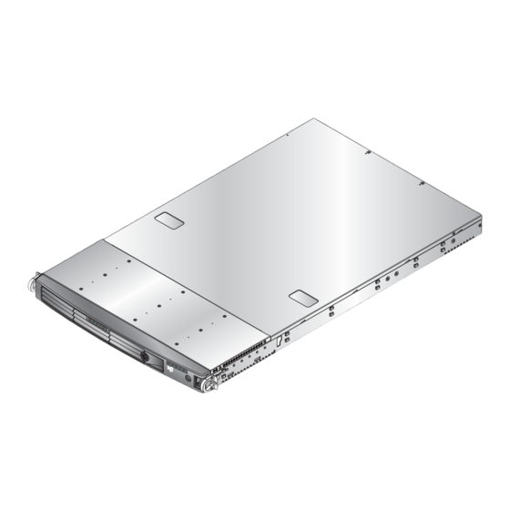
User Manuals: Silicon Graphics Altix XE320 Server
Manuals and User Guides for Silicon Graphics Altix XE320 Server. We have
1
Silicon Graphics Altix XE320 Server manual available for free PDF download: User Manual
Silicon Graphics Altix XE320 User Manual (248 pages)
Brand:
Silicon Graphics
| Category:
Server
| Size: 9 MB
Table of Contents
Table of Contents
5
Record of Revision
3
Table of Contents
21
About this Guide
23
Audience
23
Important Information
23
Chapter Descriptions
24
Related Publications
25
Conventions
26
Product Support
26
Reader Comments
27
Figure 1-1 SGI Altix XE320 Server
29
Introduction
29
Figure 1-2 Chassis Components
31
Memory
32
Node Board Features
32
Processors
32
Serial ATA (SATA)
32
Figure 1-3 Node Board Block Diagram
33
ATI Graphics Controller
34
Ethernet Ports
34
Onboard Controllers/Ports
34
Other Features
34
Pcie Expansion Slots
34
Serial Attached SCSI (SAS) and RAID Support
34
Control Panel
35
SATA/SAS Backplane/Drives
35
Server Chassis Features
35
System Power
35
Cooling System
36
Rear I/O Panel
36
System Security and Pre-Installed Linux Operating Systems
36
Server Installation
37
Unpack the System
37
Choose a Setup Location
37
Prepare for Setup
37
Rack Precautions
38
Warnings and Precautions
38
Ambient Operating Temperature
39
Mechanical Loading
39
Rack Mounting Considerations
39
Reduced Airflow
39
Server Precautions
39
Circuit Overloading
40
Identify the Sections of the Rack Rails
40
Install the System into a Rack
40
Reliable Ground
40
Figure 2-1 Identify Sections of the Rack Rails (Right Side Rail Shown)
41
Figure 2-2 Rail Assembly
41
Install the Rails
41
Figure 2-3 Attaching the Inner Bracket
42
Figure 2-4 Attaching the Rail to the Front of the Rack (View from Front of Rack)
43
Figure 2-5 Attaching the Rail to the Rear of the Rack (View from Rear of Rack)
43
Install the Server in a Rack
44
Locking Tabs
44
Figure 2-6 Install the Server in a Rack
45
Figure 2-7 Install the Server in a Third-Party Rack (1)
46
Install the Server in a Third-Party Rack
46
Access the Inside of the Chassis
49
Check the Node Board Setup
49
Check the Cpus (Processors)
50
Check the System Memory
50
Figure 2-10 Remove the Top Cover
50
Check All Cable Connections and Airflow
51
Check the Airflow
51
Check the Drive Bay Setup
51
Check the SATA/SAS Drives
51
Install Expansion Pcie Cards
51
Supply Power to the System
51
Controls and Indicators
53
Controls
53
Indicators
54
Figure 3-1 Front Panel Controls and Indicators
54
Drive Carrier Indicators
55
Advanced Node Board Setup
57
Handling the Node Board
57
ESD Precautions
58
Unpacking
58
Node Board Installation
59
Figure 4-1 Remove the Top Cover
59
Connect the Power Cables
60
Figure 4-2 Node Board Installation
61
Connecting the Control Panel
62
Figure 4-3 Control Panel Connector (JF1) Pin Definitions
62
I/O Ports
63
Processor and Heatsink Installation and Removal
63
Figure 4-4 I/O Port Locations
63
Install a Processor
64
Install a Heatsink
68
Figure 4-5 Install a CPU Heatsink
69
Remove the Heatsink
69
Removing TIM from a Processor
70
Replace the Thermal Interface Material
70
Removing TIM from a Heatsink
74
Remove the Processor
76
Install Memory
78
Memory Layout
78
Constraints for DIMM Pairs
79
Figure 4-6 Minimum Population for Dual-Channel Mode with Identical Fbdimms
79
Performance Optimization
80
Table 4-1 Recommended DIMM Configurations
80
Figure 4-7 Standard DIMM Population for Sparing or Mirroring
81
Memory Mirroring Mode
81
Memory Sparing Mode
81
Install Dimms
82
Mirroring Mode Upgrade
82
Figure 4-8 Install Dimms
83
Table 4-2 DIMM Configurations
83
Figure 4-9 Replace Dimms
84
Install or Remove the Air Shroud
85
Figure 4-10 Install Air Shrouds
85
Node Board Component Locations
86
Figure 4-11 Node Board Component Locations
86
Add Pcie Expansion Cards
87
Install a Pcie Expansion Card
87
Figure 4-12 Install a PCI Card
88
Node Board Jumpers and Connectors
89
Table 4-3 Node Board Default Jumper Settings
89
Table 4-4 Node Board Connector Descriptions
89
Table 4-5 Node Board LED Descriptions
90
Node Board Connector Pin Definitions
91
Table 4-6 Node Board Connector Pin Definitions
91
ATX Power Connector Pin Definitions
92
Auxiliary Power Connector Pin Definitions (JP10)
92
Table 4-7 ATX Power Connector Pin Definitions
92
Table 4-8 Auxiliary Power Connector Pin Definitions (JP10)
92
PW_ON Switch Pin Definitions (JF1)
93
Reset Switch Pin Definitions (JF1)
93
Overheat/Fan Pin Definitions (JF1)
93
Table 4-9 PW_ON Switch Pin Definitions (JF1)
93
Table 4-10 Reset Switch Pin Definitions (JF1)
93
Table 4-11 Overheat/Fan Fail LED Pin Definitions (JF1)
93
NIC2 LED Pin Definitions (JF1)
94
NIC1 LED Pin Definitions (JF1)
94
HDD LED Pin Definitions (JF1)
94
Table 4-12 NIC2 LED Pin Definitions (JF1)
94
Table 4-13 NIC1 LED Pin Definitions
94
Table 4-14 HDD LED Pin Definitions (JF1)
94
NIC1 LED Pin Definitions
94
Power on LED Pin Definitions (JF1)
95
NMI Switch Pin Definitions (JF1)
95
Table 4-15 Power on LED Pin Definitions (JF1)
95
Table 4-16 NMI Button Pin Definitions (JF1)
95
Fan Connector Pin Definitions (Fan1/2 - Fan7/8)
96
Chassis Intrusion Connector Pin Definitions (JL1)
96
Table 4-17 Fan Header Pin Definitions (Fan1/2 - Fan7/8)
96
Table 4-18 Chassis Intrusion Pin Definitions (JL1)
96
USB Connector Pin Definitions (USB0/USB1)
97
Table 4-19 Universal Serial Bus (USB) Pin Definitions
97
Ethernet Port (LAN1/LAN2)
98
Wake on LAN Connector Pin Definitions (JWOL)
98
Wake on Ring Connector Pin Definitions (JWOR)
98
Table 4-20 Ethernet Ports (LAN1/LAN2)
98
Table 4-21 Wake on LAN Connector Pin Definitions (JWOL)
98
Table 4-22 Wake on Ring Connector Pin Definitions
98
Jwol
98
Jwor
98
Lan1/Lan2
98
Serial Port Pin Definitions (COM2)
99
Serial General Purpose I/O Connector Pin Definitions (SGPIO)
99
Table 4-23 Serial Port Pin Definitions (COM2)
99
Table 4-24 Serial General Purpose I/O Connector Pin Definitions (SGPIO)
99
Wake on Ring Connector Pin Definitions
98
Sgpio
99
System Management Bus Power Connector Pin Definitions (J17)
100
System Management Bus Connector Pin Definitions (J18)
100
Table 4-25 SMB Power Connector Pin Definitions (J17)
100
Table 4-26 SMB Header Pin Definitions (J18)
100
Node Board Jumper Settings
101
Table 4-27 Node Board Jumper Descriptions
101
Explanation of Jumper Settings
102
Figure 4-13 Explanation of Jumper Pins
102
CMOS Memory Clear (JBT1)
103
Figure 4-14 CMOS Memory Jumper Location (JBT1)
103
I2C to Pcie Slot Jumper Settings (JPI2C1/JPI2C2)
104
Table 4-28 VGA Jumper Settings (JPG1)
104
Table 4-29 I2C to Pcie Slot Jumper Settings
104
VGA Jumper Settings (JPG1)
104
Figure 4-15 LAN 1 and LAN 2 Jumper Locations (JPL1/JPL2)
105
LAN1/LAN2 Jumper Settings (JPL1/JPL2)
105
Table 4-30 LAN1/LAN2 Jumper Settings (JPL1/JPL2)
105
Figure 4-16 Watch Dog Timer Jumper Location (JWD)
106
Table 4-31 Watch Dog Timer Jumper Settings (JWD)
106
Watch Dog Timer Jumper Settings (JWD)
106
Jwd
106
Node Board LED Descriptions
107
LAN1 and LAN2 (Ethernet Ports)
107
Power LED (LE1)
107
Table 4-32 LAN1 and LAN 2 LED Descriptions
107
Table 4-33 Power LED Description (LE1)
107
Figure 4-17 Infiniband Link LED Location (LE1)
108
Figure 4-18 Infiniband Link LED Location (LE2)
109
Infiniband Link/Activity Leds (LE2/LE3)
109
Table 4-34 Infiniband Link/Activity LED Descriptions (LE2/LE3)
109
Advanced Chassis Setup
111
ESD Precautions
111
Chassis Components
112
Figure 5-1 Chassis Front View
112
Figure 5-2 Chassis Rear View
112
Control Panel
113
Figure 5-3 JF1 Connector Location
113
Part Numbers and Marketing Codes
114
Table 5-1 Part Numbers and Marketing Codes
114
System Fans
115
System Fan Failure
115
Disk Drive Replacement
115
Disk Drive Installation
116
Figure 5-4 Disk Drive Carrier
116
Mounting a Drive in a Drive Carrier
116
Drive Replacement
117
Figure 5-5 Drive Removal
117
Power Supply
118
Power Supply Failure
118
Power Supply Replacement
118
Figure 5-6 Power Supply Replacement
119
BIOS Settings
121
Default Settings
121
Table 6-1 BIOS Default Settings
122
System BIOS
130
How to Change the Configuration Data
130
Starting the Setup Utility
130
Running Setup
131
Main BIOS Setup
132
Figure 6-1 Main BIOS Setup Menu
132
BIOS Date
133
Main Setup Features
133
System Date
133
System Time
133
Serial ATA Ports
134
Type
134
32 Bit I/O
135
LBA Mode Control
135
Multi-Sector Transfers
135
Native Mode Operation
135
SATA Controller Mode
135
Transfer Mode
135
Ultra DMA Mode
135
Extended Memory
136
ICH RAID Code Base (Available When SATA RAID Is Enabled)
136
SATA AHCI (Available When SATA RAID Is Disabled)
136
Serial ATA (SATA) RAID Enable
136
System Memory
136
Advanced Setup
137
Boot Features
137
Quickboot Mode
137
Quietboot Mode
137
ACPI Mode
138
POST Errors
138
Power Button Behavior
138
Power Loss Control
138
Resume on Modem Ring
138
Summary Screen
138
Watch Dog
138
Cache Base 0-512K
139
Cache Base 512K-640K
139
Cache Extended Memory
139
Cache System BIOS Area
139
Memory Cache
139
Default Primary Video Adapter
140
Emulated IRQ Solutions
140
Onboard Glan1/Onboard GLAN2 (Gigabit- LAN) OPROM Configure
140
Pcie Configuration
140
Pcie I/O Performance
140
Pcie Parity Error Forwarding
140
ROM Scan Ordering
140
Advanced Chipset Control
141
Enable Master
141
Large Disk Access Mode
141
Latency Timer
141
Option ROM Scan
141
Reset Configuration Data
141
Slot1 Pcie X8
141
SERR Signal Condition
142
4GB Pcie Hole Granularity
142
Memory Branch Mode
142
Branch 0/1 Rank Interleaving
142
Branch 0/1 Rank Sparing
142
Enhanced X8 Detection
142
High Bandwidth FSB
143
High Temperature DRAM Operation
143
AMB Thermal Sensor
143
Thermal Throttle
143
Global Activation Throttle
143
Snoop Filter
143
Crystal Beach Features
144
Route Port 80H Cycles to
144
Clock Spectrum Feature
144
High Precision Event Timer
144
USB Function
144
Legacy USB Support
144
Advanced Processor Options
145
C1 Enhanced Mode
145
Core-Multi-Processing
145
CPU Speed
145
Frequency Ratio
145
Machine Checking
145
Thermal Management 2
145
Adjacent Cache Line Prefetch
146
DCA Delay Clocks
146
Direct Cache Access
146
Execute Disable Bit
146
Hardware Prefetch
146
Intel Virtualization Technology
146
Intel EIST Support
147
I/O Device Configuration
147
Serial Port a
147
Serial Port B
147
Clear All DMI Event Logs
148
Console Redirection
148
DMI Event Logging
148
ECC Event Logging
148
Event Log Capacity
148
Event Log Validity
148
Event Logging
148
Mark DMI Events as Read
148
View DMI Event Log
148
BAUD Rate
149
COM Port Address
149
Console Connection
149
Console Type
149
Continue CR after POST
149
Flow Control
149
Hardware Monitor
149
CPU Temperature Threshold
150
Fan Speed Control Modes
150
Voltage Monitoring
150
Firmware Version
151
Ipmi
151
IPMI Specification Version
151
System Event Logging
151
Clear System Event Logging
152
Event Log Control
152
Existing Event Log Number
152
System Event Log/System Event Log (List Mode)
153
Realtime Sensor Data
154
Security
155
Supervisor Password Is
155
User Password Is
155
Password on Boot
156
Set Supervisor Password
156
Set User Password
156
Boot
157
Boot Priority Order/Excluded from Boot Orders
157
Exit
158
Discard Changes
159
Exit Discarding Changes
159
Exit Saving Changes
159
Load Setup Defaults
159
Save Changes
159
BIOS Power-On Self Test
161
BIOS POST Messages
161
BIOS POST Codes
167
Recoverable POST Errors
167
Terminal POST Errors
167
Table A-1 BIOS Post Codes
167
IPMI 2.0 Management Utility
175
Network Connection
177
Functions Listed on the Home Page
178
Figure B-1 BMC Remote Console
178
Remote Control
180
Figure B-2 Remote Console Screen
180
KVM Console
180
Remote Power
181
Virtual Media
181
CD-ROM Image
182
Figure B-3 CD-ROM Image
182
Drive Redirection
184
Figure B-4 Drive Redirection
184
Figure B-5 Virtual Media Options
186
Virtual Media Options
186
Chassis Control
188
Figure B-6 Chassis Control
188
System Health
188
Figure B-7 Monitor Sensors
190
Monitor Sensors
190
Table B-1 Health Monitoring Sensors
191
Figure B-8 System Event Log
192
System Event Log
192
Alert Settings
193
Figure B-9 Alert Settings
193
Change Password
194
User Management
194
Users and Groups
195
Permissions
196
KVM Settings
197
User Console
197
Figure B-10 User Console Settings
198
Figure B-11 Keyboard/Mouse Settings
200
Keyboard/Mouse
200
Device Settings
202
Figure B-12 Network Settings
202
Network
202
Dynamic DNS
204
Figure B-13 Dynamic DNS Settings
204
Security
205
Figure B-14 Security Settings
206
Certificate
208
Figure B-15 Certificate Settings
208
Date and Time
210
Figure B-16 Date and Time Settings
210
Event Log
212
Figure B-17 Event Log
212
Figure B-18 SNMP Settings
214
SNMP Settings
214
Maintenance
215
Device Information
215
Figure B-19 Device Information
216
Event Log
217
Figure B-20 Event Log
217
Figure B-21 Update Firmware
218
Unit Reset
218
Update Firmware
218
Figure B-22 Unit Reset
219
Remote Console Main Page
220
Remote Console Options
221
Log out
222
Regulatory Specifications and Safety Information
223
Manufacturer's Regulatory Declarations
223
CE Notice and Manufacturer's Declaration of Conformity
223
Server Model Number
223
Electromagnetic Emissions
224
FCC Notice (USA Only)
224
Electrostatic Discharge
225
Industry Canada Notice (Canada Only)
225
Shielded Cables
225
VCCI Class a Notice (Japan Only)
225
System Specifications
227
Table D-1 SGI Altix XE320 System Specifications
227
System Safety
231
Electrical Safety Precautions
231
Node Board Battery
232
General Safety Precautions
233
ESD Safety Precautions
234
Operating Precautions
234
Upgrading for SAS/SATA RAID Support
235
Installing the Hbas
235
Creating RAID Volumes
237
Upgrading BIOS
239
Requirements
239
Setting up the Virtual Media Boot Feature
240
Booting the Virtual Media DOS Image
241
Index
243
Advertisement
Advertisement
Related Products
Silicon Graphics Altix XE340
Silicon Graphics Altix XE210
Silicon Graphics Altix XE250
Silicon Graphics Altix XE1300
Silicon Graphics Altix ICE 8000 Series
Silicon Graphics Altix 350
Silicon Graphics 1200
Silicon Graphics 1400
Silicon Graphics 1400 Series
Silicon Graphics 1450
Silicon Graphics Categories
Server
Desktop
Storage
Monitor
Computer Hardware
More Silicon Graphics Manuals
Login
Sign In
OR
Sign in with Facebook
Sign in with Google
Upload manual
Upload from disk
Upload from URL