Table of Contents
Advertisement
Quick Links
Advertisement
Table of Contents

Summary of Contents for ROBBE-Futaba FX-32
- Page 1 Instruction Manual FX-32 No. F8078...
-
Page 2: Table Of Contents
............. 6 FUNCTIONS OF SYSTEM MENU ....39 Display ............. 40 BEFORE USE ........... 10 System Timer ..........41 ●Features of FX-32 .......... 10 User Name ............42 ●Contents and technical specifications ... 11 Sound ............... 43 ●Accessories ............12 H/W Setting ............. - Page 3 ●Common Functions ........112 screen ............. 166 Condition Select ........... 113 ●Updating ............174 AFR .............. 115 ●FX-30 / T12FG → FX-32 Model Data Dual Rate ............116 Conversion ............ 175 Program Mix ..........117 ●Airplane/Glider Functions ......121 Model Menu functions list ......121 AIL Differential ..........
-
Page 4: Introduction
Due to unforeseen changes in production procedures, the information contained in this manual is subject to change without notice. Support and Service: It is recommended to have your Futaba equipment serviced annually during your hobby’s “off season” to ensure safe operation. -
Page 5: Application, Export, And Modification
The CE symbol is applied to all such equipment, and indicates that it fulfils the currently valid European norms. An exclamation mark is also applied to radio transmitting equipment as an indication that the approved frequencies are not uniform throughout Europe. This symbol is used in all the countries of the European Union. Other nations such as Switzerland, Norway, Estonia and Sweden have also adopted this directive. -
Page 6: Definitions Of Symbols
Support and Service <Introduction>... - Page 7 LiPo Battery Safety and Handling instructions Safety Notes: • Do not submerge the battery in water or any other liquid. • Do not heat or incinerate the battery, or place it in a microwave oven. • Do not short-circuit the pack or charge it with reversed polarity. • Do not subject the battery to physical pressure; do not deform or throw it. • Do not solder directly to the battery. • Do not modify or open the battery. • Do not charge the battery to a voltage higher than 4.2 Volts per cell, or discharge it to a voltage lower than 2.5 Volts per cell. • LiPo batteries may only be charged using a charger designed expressly for this purpose. Never connect the battery directly to a mains PSU. • Never charge or discharge the battery in direct sunshine, or close to a heater or fire. • Do not use the battery in any location that is subject to severe static discharges. • Any of these errors may cause the battery to be damaged, explode or catch fire. • Keep the battery well out of the reach of children. If electrolyte should escape, keep it well away from fire; the substance is highly inflammable and may burst into flames. • Avoid the fluid electrolyte contacting your eyes. If this should occur, rinse the affected part immediately with plenty of clean water before seeking medical attention. •...
- Page 8 Secure Digital (SD) Memory Card Handling Instructions (SD card is not included with this set) Never remove the SD card or turn off power Do not expose the SD card to dirt, moisture, water while entering data. or fluids of any kind. Never store the SD card where it may be subject Always hold the SD card by the edges during to strong static electricity or magnetic fields.
- Page 9 Notes: <Introduction>...
-
Page 10: Before Use
FX-32 is operated by a 7.4 V/3,400 mAh Lithium Polymer battery. SD card (Secure Digital memory card) (Not included) Model data can be saved to an SD card (SD:32MB-2GB SDHC:4GB-32GB). When FX-32 transmitter software files are released, the software can be updated by using an SD card update. -
Page 11: Contents And Technical Specifications
Weight: 0.38 oz. (10.9g) (*1) When using ESC's make sure that the regulated output capacity meets your usage application. Note: The battery in the FX-32 transmitter is not connected to the battery connector at initial. Please connect the battery connector before use. -
Page 12: Accessories
[RPM sensor optical type : SBS-01RO] [GPS sensor : SBS-01G] [Voltage sensor : SBS-01V] • Neckstrap - a neckstrap may be connected to your FX-32 system to make it easier to handle and improve your flying precision since your hands won’t need to support the transmitter’s weight. -
Page 13: Transmitter Controls
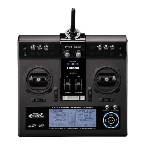
Transmitter controls Antenna Monitor LED Volume Switch Switch RotaryTrim RotaryTrim LinearSlider LinearSlider Stick Stick (J3) (J2) (J4) (J1) RotaryTrim RotaryTrim U.menu/Mon Button Home/Exit Button SensorTouch Power Switch <Before Use>... -
Page 14: Cautions On Handling Antenna
Monitor LED display High power High power The status of the transmitter is displayed by LED at the upper part of the front of a FX-32. FASSTest mode → Light Blue light FASST mode → Green light S-FHSS mode → Yellow-green light RF-OFF →... -
Page 15: Switch (Sa-Sh)
T5 (right), T6 (Left): The upper rotary trimmers T5 and T6 offer analog input. *The FX-32 transmitter beeps when the lever comes to the center. *You can select a slide lever and set the movement direction on the setting screen of mixing functions. -
Page 16: Touch Sensor
Touch sensor operation Data input operation is performed using the touch sensor. SensorTouch™ operation Condition Working • Short 'tap' If the screen has more than one page. The cursor moves to the top of next page. If the screen have only one (1) page. The cursor moves to the top of page. -
Page 17: Stick Adjustment
Note: 1. Hold the lever head "B" and turn the lever head "A" counter-clockwise. The lock will be released. *Scroll operation: Circle your finger on the outside edge of 2. Turn the lever-head "A" clockwise as you hold the the RTN button. The sensors may mis-read your touch as a lever-head "B"... -
Page 18: Sd Card
SD card reader/writer Saving model data and update files (released from Futaba) into the SD card, you can use those files on your FX-32 transmitter. Equipment for reading and writing SD cards is available at most electronics stores. -
Page 19: How To Remove A Rear Case
How to remove a rear case: A rear case is removed when performing battery exchange, stick tension adjustment, and switch exchange. Take care not to break an internal electronic board, wiring, and parts. <Before Use>... -
Page 20: Connector/Plug
Connector/Plug Connector for battery charger This is the connector for charging the LiPo battery 7,4V/ 3,400mAH that is installed in the transmitter. Do not use any other chargers except the attached special charger. WARNING Do not connect any other chargers except the special charger to this charging connector. -
Page 21: Installation And Removal Of The Battery
4. Close the rear case completely. WARNING Be careful not to drop the battery. Never disconnect the battery connector from the FX-32 transmitter after turning off the power until the screen is completely blank and the transmitter has shut down completely. -
Page 22: Receiver Nomenclature
Receiver nomenclature DANGER Before using the receiver, be sure to read the precautions listed in the following pages. Don't connect a connector, as shown in a before figure. Receiver R7008SB *It will short-circuit, if it connected in this way. A short circuit across the battery terminals may cause abnormal heating, fire and burns. - Page 23 6. Once locked into the correct mode the LED will change to a solid color. The FX-32 has the ability to link to two 7. Please cycle the receiver(s) power off and back on again after changing the Channel Mode.
-
Page 24: Receiver's Antenna Installation
Receiver's Antenna Installation The R7008SB has two antennas. In order to maximize signal reception and promote safe modeling Futaba has adopted a diversity antenna system. This allows the receiver to obtain RF signals on both antennas and fly problem-free. *Must be kept as straight as possible. -
Page 25: Safety Precautions When Installing Servos
Mounting the Servo Safety precautions when you install receiver and servos Wood screw 2.3-2.6mm nut WARNING washer Rubber Rubber grommet grommet Connecting connectors Brass eyelet Brass eyelet Servo mount Servo mount Be sure to insert the connector until it 2.3-2.6mm screw stops at the deepest point. -
Page 26: S.bus/S.bus2 Installation
●When using S.BUS/S.BUS2, special settings and mixes in your transmitter may be unnecessary. ●The S.BUS/S.BUS2 servos memorize the number of channels themselves. (settable with the FX-32) ●The S.BUS/S.BUS2 system and conventional system (receiver conventional CH used) can be mixed. -
Page 27: S.bus Wiring Example
S.BUS Wiring example *When using 8/SB as S.BUS, you have to set CH Mode of the mode B or mode D. Since the channel number is memorized by the S.BUS itself, any connector can be used. When Battery the SBD-1 (sold separately) is used, ordinary S.BUS Port servos can be used with the S.BUS system. -
Page 28: S.bus2 System
S.BUS2 System Using the S.Bus2 port an impressive array of telemetry sensors may be utilized. S.BUS2 TABLE S.BUS2 S.BUS servo servo Receiver port Telemetry sensor S.BUS2 S.BUS gyro gyro S.BUS ○ ○ × S.BUS2 × (※) ○ ○ ~~~ Don't connect S.BUS servo, S.BUS gyro to BUS2 connector. -
Page 29: S.bus/S.bus2 Devicesetting
S.BUS/S.BUS2 device setting S.BUS/S.BUS2 servos or a telemetry sensor can be connected directly to the FX-32. Channel setting and other data can be entered for the S.BUS/S.BUS2 servos or sensors. 1. Connect the S.BUS device you want to set with FX-32 as shown in the figure. -
Page 30: Telemetry System
*Telemetry is available only in the FASSTest 18CH mode. (12CH mode displays only receiver battery voltage and extra battery voltage.) *The telemetry function requires the corresponding receiver (R7008SB). * Telemetry display only FX-32 ID of R7008SB was remembered to be. FX-32 Your aircrafts data can be checked in the transmitter by connecting various telemetry sensors to the S.BUS2 connector of the... -
Page 31: Basic Operation
BASIC OPERATION Battery Charging Before charging batteries, read the "Cautions for handling battery and battery charger" in the section "LiPo Battery Safety and Handling Instructions". How to charge the LiPo battery 7,4V/ 3,400mAH for the transmitter The RC charger included in the set is suitable for charging 7.4 Volt Lithium batteries, and features a voltage- controlled automatic cut-off circuit (8.4 Volts). -
Page 32: How To Turn On/Off The Transmitter
W h e n t u r n i n g o n t h e p o w e r, t h e F X - 3 2 If so desired, the FX-32 transmitter can indicate transmitter will begin emmiting RF automatically the owner's name. -
Page 33: Home Screen
Home screen Use the touch sensor to select the following display area to call each setting screen, and push the EDIT button. The setting screen appears. Airplane/Glider Home Screen Model Name Timer display screen • The model name that • When the cursor is currently used is is moved to the displayed here. - Page 34 Helicopter Home Screen Throttle/Pitch Position Display • Throttle and pitch position is displayed here. Push the EDIT button to call the throttle curve or pitch curve setting screen directly. *Condition hold operation is displayed. ("IS ON") To activate/deactivate Condition Hold: 1.Move the cursor to [CND HOLD]. 2.Set the throttle stick lower than the 1/3 point and push the EDIT button to activate/deactivate the...
-
Page 35: Screen Lock
Auto Lock functions automatically when the model changes or power is turned on. *To temporarily allow access to the FX-32 programming press and hold the S1 bitton for one second. Please note, the Auto Lock function timer will resume immediately once again. -
Page 36: Link Procedure (T14Sg/R7008Sb)
Link procedure (FX-32/R7008SB) Each transmitter has an individually assigned, unique ID code. In order to start operation, the receiver must be linked with the ID code of the transmitter with which it is being paired. Once the link is made, the ID code is stored in the receiver and no further linking is necessary unless the receiver is to be used with another transmitter. - Page 37 10. When a telemetry function is enabled, the receiving interval (down-link interval) of sensor data can be changed. If a DL interval is increased, the response of the sensor data display becomes slower, but stick response will improve. Initial value: 1.0s Adjustment range: 0.1s~2.0s * If there are many FASSTest systems turned on around your receiver, it might not link to your transmitter.
-
Page 38: Range Testing Your R/C System
It is extremely important to range check your models prior to each flying session. This enables you to ensure that everything is functioning as it should and to obtain maximum enjoyment from your time flying. The FX-32 transmitter incorporates a system that reduces its power output and allows you to perform such a range check. -
Page 39: Functions Of System Menu
SYSTEM MENU The System Menu sets up functions of the transmitter: This does not set up any model data. ● Select [SYSTEM] at the home screen and call the system menu shown below by touching the RTN button. ● Scrolling the touch sensor to select the function you want to set and call the setup screen by touching the RTN button. -
Page 40: Display
Backlight brightness adjustment *To temporarily allow access to the FX-32 programming press and hold the S1 button for one second. Please note, 1 . S c r o l l i n g t h e t o u c h s e n s o r t o s e l e c t the Auto Lock function timer will resume immediately once "BACKLIGHT BRIGHTNESS"... -
Page 41: System Timer
● FX-32 has two type system timers. ● System timer displayed on the home screen TOTAL timer: Displays the total accumulated can be selected. -
Page 42: User Name
USER NAME User name registration This function registers the FX-32 user name. *A name of up to 12 characters can be entered as the user name. (Space is also counted as 1 character.) ● Select [USER NAME] at the system menu and call the setup screen shown below by touching the RTN button. -
Page 43: Sound
SOUND Turns off the buzzer. 3 independent sound volumes: "WARNING", "VOICE" and others, are available. "LOW BATTERY" adjusts low battery alarm voltage to match a battery. ● Select [SOUND] at the system menu and access the setup screen shown below by touching the RTN button. -
Page 44: H/W Setting
Note: This will not change the throttle ratchet, etc. Those are mechanical changes that must be done by a Futaba service center. Note: After changing the mode, it is applied when setting a new model. It is not applied to an existing model. - Page 45 Stick calibration method Operation switch setting method 1.Select [SWITCH] and call the setup screen *J3 and J4 correction is described below. J1 and J2 corrections are performed using the same procedure. shown below by touching the RTN button. 1.Select [CALIBRATION] and access the setup screen shown below by touching the RTN button.
-
Page 46: Information
INFORMATION Displays the program version, SD card information, and product ID. The FX-32 system program version information, The language displayed in home, menu, and SD card information (maximum and vacant number setup screen is selectable. of model data), and product ID are displayed on the Moreover, the unit of a telemetry display can Information screen. -
Page 47: Range Check
RF operation as noted on the display. "NO" is chosen and [RTN] is pushed. *Once the FX-32 is transmitting at full power, it is not *For safety, the RANGE CHECK mode can not be selected possible to enter the Range Check mode without first while the RF transmission is active. -
Page 48: S.bus Servo
●Servo ID number Individual ID numbers are memorized for your S.BUS servos in your FX-32. When a servo is used (as shown at the right), the servo ID number is automatically read by the transmitter. - Page 49 S.BUS Servo Description of function of each parameter *There are a function which can be used according to the kind of servo, and an impossible function. • ID Displays the ID of the servo whose parameters are to be read. It cannot be changed. •...
- Page 50 • Boost ON/OFF OFF : It is the boost ON at the time of low-speed operation.(In the case of usual) ON : It is always the boost ON.(When quick operation is hope) • Damper The characteristic when the servo is stopped can be set. When smaller than the standard value, the characteristic becomes an overshoot characteristic.
-
Page 51: Model Basic Setting Procedure
3. Fuselage linkage 1. Model addition and call Connect the ailerons, elevators, throttle, rudder, Initial setting assigns 1 model to the FX-32 etc. in accordance with the model's instruction transmitter. The Model Select function of the manual. For a description of the connection Linkage Menu is used to add models and to select method, see the Receiver and Servos Connection. - Page 52 can be fine-tuned by setting a VR. You can also set the Auto Mode, which will link Airbrake to a stick, switch, or dial. A separate stick switch or dial can also be set as the ON/OFF switch. 5. Idle down setting The idling speed can be lowered with one touch by a switch without changing the throttle trim 8.
-
Page 53: Helicopter
Helicopter basic setting procedure This section outlines examples of use of the helicopter functions of the FX-32. Adjust the actual values, etc. to match the fuselage used. 1. Model addition and call *For a description of the swash type selection, refer to the MODEL TYPE function. - Page 54 "Receiver and Servos Connection". Note: The channel assignment of the FX-32 is different from that of our existing systems. (The channel assigned to each function can be checked at the Function menu of the Linkage Menu.)
- Page 55 6. AFR (D/R) Model Menu, and set the curve for each condition. (At initial setting, this function is in the "INH" AFR (D/R) function is used to adjust the throw state. To use it, set it to the "ON" state.) and operation curve of aileron, elevator and rudder for each condition.
- Page 56 11. Swash Mix corrects aileron, elevator and pitch interaction The swash mix function is used to correct the swash plate in the aileron (Left/Right Cyclic) and elevator (Forward/Aft Cyclic) direction corresponding to each operation of each condition. 12. Throttle mixing setting *If throttle mixing is necessary for a compensation for slowing of engine speed caused by swash plate operation during aileron or elevator operation, please refer to the...
-
Page 57: Receiver And Servos Connection
Receiver and servos connection Connect the receiver and servos in accordance with the connection diagram shown below. Always read [Precautions when mounting the receiver and servos] and [Before using]. When mounting the receiver and servos to the fuselage, connect the necessary points in accordance with the kit instruction manual. Receiver and servos connection diagram ●Always connect the necessary number of servos. -
Page 58: Servo Connection By Model Type
Servo connection by model type The FX-32 transmitter channels are automatically assigned for optimal combination according to the type selected with the Model Type function of the Linkage Menu. The channel assignment (initial setting) for each model type is shown below. Connect the receiver and servos to match the type used. - Page 59 ●Ailevator 1AIL 2AIL 2AIL+1FLAP 2AIL+2FLAP Glider Glider Glider Glider Airplane Airplane Airplane Airplane Aileron Aileron Aileron Aileron Aileron Aileron Aileron Aileron Aileron Aileron Aileron Aileron Elevator Elevator Elevator Elevator Elevator Elevator Elevator Elevator Elevator Elevator Elevator Elevator Throttle Motor AUX7 Throttle Motor AUX7...
- Page 60 ●Tailless wing 2AIL 2AIL+1FLAP 2AIL+2FLAP Glider Glider Glider Airplane Airplane Airplane Aileron Aileron Aileron Aileron Aileron Aileron Aileron Aileron Aileron AUX4 AUX4 AUX4 AUX4 AUX4 AUX4 AUX4 AUX4 AUX4 Throttle Motor AUX7 Throttle Motor AUX7 Throttle Motor AUX7 Rudder Rudder Rudder Rudder Rudder...
- Page 61 ●Tailless wing Winglet 2Rudder 2AIL 2AIL+1FLAP 2AIL+2FLAP Glider Glider Glider Airplane Airplane Airplane Aileron Aileron Aileron Aileron Aileron Aileron Aileron Aileron Aileron RUD2 RUD2 RUD2 RUD2 RUD2 RUD2 RUD2 RUD2 RUD2 Throttle Motor AUX7 Throttle Motor AUX7 Throttle Motor AUX7 Rudder Rudder Rudder...
- Page 62 Helicopter ●FASSTest 18CH / FASST MULTI / FASST 7CH / S-FHSS H-4/H-4X Swash All Other Aileron Aileron Elevator Elevator Throttle Throttle Rudder Rudder Gyro Gyro Pitch Pitch Governor Governor Elevator2 Governor2 GYRO2 GYRO2 GYRO3 GYRO3 Governor2 Needle Needle AUX5 AUX4 AUX3 AUX2 AUX1...
-
Page 63: Functions Of Linkage Menu
FUNCTIONS OF LINKAGE MENU The Linkage Menu is made up of functions The functions which can be selected depend on which perform model addition, model type the model type. A typical menu screen is shown selection, frequency setting, end point setting, and below. -
Page 64: Servo Monitor
SERVO MONITOR Servo Test & Graph Display / Displays servo positions. This is used for testing servo movement. In order to prevent any potential difficulties, “Moving Test” (repetition mode) and “Neutral the servo test function will be inoperable, or Test” (fixed position mode) are available. inaccessible, under certain conditions. -
Page 65: Model Select
This function is used to load the settings of the always appears in the display screen. desired model into the FX-32’s memory. The Copy function is used to copy one set of model The settings may be selected from either the data into a second memory within the transmitter and transmitter’s built-in memory or a SD card (32MB-... - Page 66 *The current model's name can be changed. *FX-32 accepts a SD card formatted FAT file system, but 1.Use the touch sensor to select the current it does not supports the long file name feature used in model in the model list and then touch the Windows or other modern operating systems.
-
Page 67: Model Type
MODEL TYPE This function selects the model type from among airplane, helicopter, and glider. Seven types of main wings and three types When the Model Type Selection command is accessed, all of the data in the active memory is of tail wings are available for airplanes. Eight cleared (except the following swash type.) Be sure swash types are available for helicopters. - Page 68 Model type ●Model type selection Select the model type f r o m a m o n g a i r p l a n e , helicopter, and glider. (Airplane, glider) (Helicopter) ●Wing type selection ●Swash type selection Helicopter swash type ●Wing type selection (Normal) Select from among H-1, H-2, H-4, HR3, HN3, H-3, HE3, and H4X.
- Page 69 Model type selection (Airplane, Glider) ●Wing type (Normal) ●Wing type (Tailless wing) ●Rudder type ●Tail type Model type selection (Helicopter) ●Swash type <Functions of Linkage Menu>...
-
Page 70: System Type
System Type selection Dual receiver function (only FASSTest 18CH mode) The FX-32 is for 2.4GHz only. The system can be changed from among 5 choices: FASSTest Dual receivers can be linked with the FX-32. 1 8 C H , FA S S Te s t 1 2 C H , FA S S T M U LT I , Two receivers are recognized individually by ID FASST 7CH, S-FHSS. - Page 71 Telemetry function (FASSTest mode only) 3. Touch the RTN button to end adjustment and return to the cursor mode. To use the telemetry function, set “Telemetry” to “ACT”. Telemetry ACT/INH procedure DL Interval (FASSTest mode only) 1. Move the cursor to the TELEMETRY [ACT] item When a telemetry function is enabled, the and touch the RTN button to switch to the receiving interval (down-link interval) of sensor...
- Page 72 The example for choosing System Type R2006GS R2106GF R617FS R2008SB R6004FF R608FS R616FFM R6008HS R7008SB R6106HF R6108SB R7003SB R6106HFC R6208SB R6203SB R6014HS R7008SB R6203SBE R6014FS R7003SB R6202SBW R6203SB R6303SB R6203SBE R6303SBE R6202SBW R6303SB R6303SBE System Type ■ FASSTest 18CH --- FASSTest system receiver mode. Applicable with the telemetry sensor unit. Up to 18 channels (linear 16+ON/OFF2) can be used.
-
Page 73: Function
FUNCTION Channel assignment of each function can be changed. When you select model and wing (swash) types, channels and two digital channels. For FASSTest you will find that the optimized combinations of 18CH mode, you can set 10 linear channels and servo output channels and functions have been two digital channels. - Page 74 Trim setting WARNING Use the touch sensor to move the cursor to As a safety precaution to prevent the motor from the "TRIM" item of the channel you want to starting unexpectedly, please switch off the change and touch the RTN button. motor accordingly.
-
Page 75: Sub-Trim
SUB-TRIM Setting of neutral position of each servo. The Sub-Trim function is used to set the servo neutral position, and may be used to make fine adjustments to the control surface after linkages and touchrods are hooked up. When you begin to set up a model, be sure that the digital trims are set to their center position. -
Page 76: Servo Reverse
SERVO-REVERSE Use to reverse the throw direction. Servo Reverse changes the direction of an that control multiple servos, it may be confusing individual servo’s response to a control stick to tell whether the servo needs to be reversed or a movement. -
Page 77: Fail Safe
For safety, always set the fail safe functions. mode: CH3 only) ●Remember to set the throttle channel fail safe function so that The FX-32 system also provides you with the servo moves to the maximum slow side for airplanes and an advanced battery monitoring function that to the slow side from the hovering position for helicopters. -
Page 78: End Point
END POINT Sets the travel, limit point, and speed of each servo. The End Point function adjusts the left and right NOTE: The servo speed setting is used to set the servo delay for each channel, from channel l to channel 12. The system servo throws, generates differential throws, and uses the programmed speed (delay) to slow down servo will correct improper linkage settings. -
Page 79: Throttle Cut (Air/Heli Only)
THROTTLE CUT Stops the engine safely and easily.(airplane and helicopter only) Throttle cut provides an easy way to stop the engine, by flipping a switch with the throttle stick at idle. The action is not functional at high throttle to avoid accidental dead sticks. The switch’s location and direction must be chosen, as it defaults to NULL. -
Page 80: Idle Down (Air/Heli Only)
IDLE DOWN Lowers the engine idling speed.(airplane and helicopter only) The Idle Down function lowers the engines idle by flipping a switch with the throttle stick at idle. The action is not functional at high throttle to avoid accidental dead sticks. The switch’s location and direction must be chosen, as it defaults to NULL. -
Page 81: Swash Ring (Heli Only)
SWASH RING Limits the swash plate travel to within a fixed range. (Helicopter only) This function limits the swash travel to within a fixed range to prevent damaging of the swash linkage by simultaneous operation of the ailerons and elevators. It is effective in 3D aerobatics which use a large travel. -
Page 82: Swash (Heli Only, Except H-1)
SWASH Swash operation linkage correction function.(helicopter only, except swash type H-1) Neutral Point The following compensation mixing is possible; PIT to AIL, PIT to ELE, AIL to PIT, ELE to AIL, At your linkages, if the servo horn deviates from and ELE to PIT (HR3 mode.) It adjusts the swash- a perpendicular position at neutral, the linkage plate to operate correctly for each control using the... - Page 83 Mixing rate setting procedure The HR-3 is taken as an example to describe mixing rate setting. Mixing applied in other swash modes is different, but the setting procedure is the same. *When making the following setting, use the touch sensor to move the cursor to the item you want to set and touch the RTN button to switch to the data input mode.
-
Page 84: Timer
TIMER Timer setting Each timer may be set for count-down or count The Timer function may be set for any desired time, up operation with a target time. i.e. engine run time, specified times for competitions, If a target time is set and the timer reaches the set etc. - Page 85 Alarm mode *A mode which sounds an alarm every minute during the remaining time up to the timer alarm time. 1. Change the setting by pressing ↑ or ↓ button. [ ↑ ]: An alarm sounds every minute of the elapsed time from timer start.
-
Page 86: T1-T6 Setting
T1-T6 SETTING Digital trim settings This function adjusts the digital trim's control step amount and operation mode (T1~T6.) When the flight conditions are set, the trim operation can be coupled with among all the conditions which combination mode is selected. ●... -
Page 87: Multiprop
MULTIPROP CH is extended by MPDX-1 of an option The system has compatible with the Futaba MPDX-1 multiprop decoder. One channel can be expanded to 8 channels by using the MPDX- 1 multiprop decoder. Up to two MPDX-1 can be used. -
Page 88: Function Name
FUNCTION NAME Function name can be changed T h e n a m e o f t h e s p a r e f u n c t i o n s (AUXILIARY1-8) can be changed for the full name (10 characters) or for the abbreviated name (4 characters). -
Page 89: Telemetry
TELEMETRY Displaying data from the receiver This screen displays your choice of data from the *It cannot be used in FASST mode and S-FHSS mode. receiver. *Only receiver voltage and EXT voltage can be used in FASSTest12CH mode. Also warnings can be activated regarding *The FASSTest18CH mode can use all the telemetry functions. -
Page 90: Telemetry:receiver [Battery]
TELEMETRY : RECEIVER [BATTERY] Displaying data from the receiver battery voltage In this screen, the battery voltage of a receiver is *It cannot be used in FASST mode and S-FHSS mode. displayed. *Only receiver voltage and EXT voltage can be used in FASSTest12CH mode. -
Page 91: Telemetry:receiver [Ext-Batt]
TELEMETRY : RECEIVER [EXT BATT.] Displaying data from the EXT battery voltage port *CA-RVIN-700 must be installed in the aircraft. The EXT-VOLT screen will display the data from You will be alerted by an alarm or vibration if the EXT-battery output from the R7008SB receiver. the voltage set by you is exceeded. -
Page 92: Telemetry:temperature
TELEMETRY : TEMPERATURE Displaying data from the temperature *A temperature sensor must be installed in the aircraft. Temperature is a screen which displays/sets *It cannot be used in FASST mode and S-FHSS mode. up the temperature information from an optional *Only receiver voltage and EXT voltage can be used in temperature sensor. -
Page 93: Telemetry:rpm Sensor
TELEMETRY : RPM SENSOR Displaying data from the RPM *A RPM sensor must be installed in the aircraft. RPM sensor is a screen which displays / sets up alarm and/or vibration will alert you. the rotation information from an optional RPM *It cannot be used in FASST mode and S-FHSS mode. -
Page 94: Telemetry:altitude
TELEMETRY : ALTITUDE Displaying data from the altitude *An altitude sensor or GPS sensor must be installed in the aircraft. ALTITUDE is a screen which displays / sets up the get lower as you go up in altitude, using this the sensor altitude information from an optional altitude sensor or will estimate the altitude. -
Page 95: Telemetry:altitude [Variometer]
*The FASSTest18CH mode can use all the telemetry functions. To ensure that the pilot is aware as to the model's ● Variometer status, the FX-32 incorporates a different melody ● The maximum and the minimum when powering ON are shown. It will be preset, if a cursor is moved to this place and the RTN ●... -
Page 96: Telemetry:voltage [Battery]
TELEMETRY : VOLTAGE [BATTERY] Displaying data from the battery voltage *SBS-01V must be installed in the aircraft. In this screen, the battery voltage is displayed. *It cannot be used in FASST mode and S-FHSS mode. In order to use this function, it is necessary to *Only receiver voltage and EXT voltage can be used in connect External voltage connector of R7008SB ⇔... -
Page 97: Telemetry:voltage [Ext-Batt]
TELEMETRY : VOLTAGE [EXT-VOLT] Displaying data from the EXT battery voltage port *SBS-01V must be installed in the aircraft. In this screen, the EXT battery voltage is *It cannot be used in FASST mode and S-FHSS mode. displayed. In order to use this function, it is *Only receiver voltage and EXT voltage will be received in the FASSTest12CH mode. -
Page 98: Telemetry:gps [Distance]
TELEMETRY : GPS [DISTANCE] Displaying data from the Distance Screen *A GPS sensor must be installed in the aircraft. *The GPS sensor is necessary, and is sold separately. Mount The Distance screen displays and sets altitude and connect the sensor in accordance with the sensor d a t a f r o m a n S B S - 0 1 G G P S S e n s o r ( s o l d instruction manual. - Page 99 First, the set of a reference is required. Setting a "too close" alarm distance 1. The model and transmitter to which the GPS 1. Move the cursor to the ↓ALARM item, and sensor was connected are turned on. it chooses from BUZZER, VOICE, INHIBIT, and 2.
-
Page 100: Telemetry:gps [Speed]
TELEMETRY : GPS [SPEED] Displaying data from the speed *A GPS sensor must be installed in the aircraft. The speed screen displays and sets the speed data *The GPS sensor is necessary, and is sold separately. Mount from an SBS-01G (GPS sensor) sold separately. and connect the sensor in accordance with the sensor instruction manual. -
Page 101: Telemetry:gps [ Altitude,Variometer,Position ]
TELEMETRY : GPS [ALTITUDE, VARIOMETER, POSITION] *A GPS sensor must be installed in the aircraft. The altitude, variometer, position screen displays and sets the data from an SBS-01G (GPS sensor) sold separately. *The GPS sensor is necessary, and is sold separately. Mount and connect the sensor in accordance with the sensor instruction manual. -
Page 102: Sensor
SENSOR Various telemetry sensors setting [What is a slot?] This screen registers the telemetry sensors used Servos are classified by CH, but sensors are with the transmitter. When only one of a certain classified in units called “slot”. There are slots type of sensor is used, this setting is unnecessary from No. -
Page 103: Sensor:reload
This page is set when using multiple telemetry sensors of the same type. When using multiple sensors of the same type the sensors must be registered in the transmitter. Connect all the sensors to be used to the FX-32 as 3-way hub or Y-harnesses... -
Page 104: Sensor:change Slot
RTN button. Sensor slot change 1. Connect the sensor to be changed to the FX-32 through a hub as shown in the figure above. 2. Move the cursor to “CHANGE SLOT” on page 3/3 of the <Sensor> screen. -
Page 105: Tele. Setting
TELE. SETTING Speech interval set , data logging of telemetry. The set of the speech interval of teremetry data, and a switch setup for carrying out logging of the teremetry data to SD card and a setup of a logging interval are carried out. -
Page 106: Warning
WARNING Mixing warning normal reset The warning display at power ON can be turned ON/OFF for each function. Use by setting functions which may be dangerous if operated at power ON to ON. Initial setting is all ON. ● Select [WARNING] at the linkage menu and call the setup screen shown below by touch the RTN button. -
Page 107: Trainer
"FUNC" or "MIX" mode. Instructors’ transmitter should be programmed for 2. When the FX-32 is used as the instructor’s trainer operation, as described below. transmitter, set the modulation mode of the When the Instructor activates the trainer switch, student’s transmitter to PPM. - Page 108 "16/12/8 CH": When the student uses the FX- "16/12/8 CHANNEL": When the student uses 32,T14SG, T18MZ, select [16CH]. When the the FX-32 (including the T18MZ, T14SG)select student uses the T14MZ, T12Z, T12FG or FX-40, [16CH]. Otherwise select [12CH]or[8CH]. select [12CH]. Otherwise select [8CH].
- Page 109 *Use the touch sensor scrolling to move the cursor to the "MODE" item of the channel you want to change and touch the RTN button to switch to the data input mode and change the mode by turning the touch sensor to the left or right. The display blinks.
-
Page 110: Data Reset
DATA RESET Model memory setting data reset. (by item) This function is designed to allow you to reset All model setting: selected portions or all of the settings saved in Resets all Linkage and Model menu functions the active model memory. You may individually except for frequency, model select, and model type. -
Page 111: Cond.hold
COND.HOLD Condition hold function This function may be used to fix the maximum To activate/deactivate condition hold: speed of the engine so that you may adjust flight (Home screen) conditions when the engine is running. An alarm 1. Move the cursor to [CND HOLD]. indicates that the function is operating. -
Page 112: Functions Of Model Menu
Select function to add flight conditions. (Up to 8 and other functions common to all model types. conditions can be used) Note: The FX-32 is designed so that the airplane Before setting the model data, use the Model and glider (including EP glider) model types are Type function of the Linkage Menu to select the compatible with aircraft of similar type wings. -
Page 113: Condition Select
CONDIT. SELECT Flight condition's addition, deletion, copy, condition renaming, and condition delay can be set. [All model types] The functions in the Model Menu can be used by when there are sudden changes in the servo positions and when there are variations in switching the settings of up to 8 flight conditions the operating time between channels during by using the Condition Select function to add flight condition switching can be suppressed. The conditions. - Page 114 Condition name change "DESTIN.CND." (copy destination) and touch the RTN button. 1. Use the touch sensor to move the cursor to *The models already saved are displayed at the right side of the condition you want to change in the the screen. conditions list. 7. After using the touch sensor to move the *The number before the condition name become reverse- cursor to the copy destination condition, video to show that it is to be deleted.
-
Page 115: Afr
The angle and curve of each operation function can be set. [All model types] ● Operation curve adjustment: Three types AFR function is used to adjust the throw and of curves (EXP1, EXP2, and POINT) can be operation curve of the stick, lever, and switch selected. A maximum 17 points curve can be functions for each flight condition. This is normally used for the point curve type. (Initial setting: used after End Point has defined the maximum 9 points) The number of points can also be... -
Page 116: Dual Rate
[All model types] DUAL RATE D/R curves which can be switched by switch, etc. can be added. The curve can be adjusted by the AFR function. ● Up to 6 rates can be added for each condition. ● D/R is set for each condition and is not reflected at other conditions. -
Page 117: Program Mix
PROG. MIXES Program mixing which can be freely customized. Up to 10 mixings can be used for each condition. [All model types] time can be adjusted. Programmable mixing may be used to correct undesired tendencies of the aircraft, and it may also The Programmable mixing includes a powerful be used for unusual control configurations. Mixing link function, which allows Programmable mixing means that the motion of a command channel, to be linked with the special mixing functions, or called the "master,"... - Page 118 ●Link setting ●Master CH ●Trim mode setting ●Slave CH ●Slave CH AFR mode ●Fine tuning trim setting (For a description of the setting method, see the description at the back of this manual.) ●Servo speed setting (For a description of the setting method, see the description at ●ON/OFF the back of this manual.) ●Mix ON/OFF delay ●Switch selection (For a description of the switch setting method, see the...
- Page 119 switch to the data input mode. Initial value: 0.0 sec Select the function by scrolling the touch Adjustment range: 0~4 sec sensor and touch the RTN button. (When the RTN button is touched for 1 second, the delay time 2. When you want to link this mix with other is reset to the initial value.) mixes, move the cursor to the [LINK] item and Touch the RTN button to end adjustment and touch the RTN button to switch to the data return to the cursol move mode.
- Page 120 3. After setting, switch to the cursor move mode by touching the RTN button. *At adjustment, the offset rate is reset to the initial value by touching the RTN button for 1 second. ●Fine tuning trim setting Operation control [CTRL], operation mode [MODE], and rate [RATE] adjustment is possible by [FINE TUNING] item. (For a description of the fine tuning trim setting method, refer to [Fine tuning trim setting] at the back of this manual.) ●Operation mode setting...
-
Page 121: Airplane/Glider Functions
Condition Select function to add flight conditions. this Model Menu functions section. First use the (Up to 8 conditions can be used) Model Type function of the Linkage Menu to Note: The FX-32 is designed so that the airplane and glider model types can handle aircraft of the same preset the model type, wing type, and tail type wing type. - Page 122 RUD to AIL GYRO This is a dedicated mix when a GYA Series gyro is This mix is used to correct roll maneuvers, used. [Airplane/glider, general] knife edge, etc. of stunt planes. [Airplane/glider, V-TAIL general] This function adjusts the elevators and rudder of CAMBER Mix V-tail models. [Airplane/glider, V-tail specifications] This mix adjusts the camber and corrects the AILEVATOR elevators. [Airplane/glider, 2 ailerons or more] This function adjusts the elevators and ailerons of ELE to CAMBER models with elevator specifications. [Airplane/ This mix is used when you want to the mix camber glider, elevator specifications] flaps with elevator operation. Lifting force can WINGLET be increased at elevators up. [Airplane/glider, 2 This function adjusts the left and right rudders ailerons or more] of winglet models. [Airplane/glider, winglet...
-
Page 123: Ail Differential
AIL DIFF. [Airplane/glider, 2 ailerons or more] The left and right aileron differential can be adjusted independently. The differential rate can also be adjusted according to the flying state by setting a fine tuning VR. (Currently selected condition name) ● Select [AIL DIFF.] at the model menu ● Group/single mode switching and call the setup screen shown below by touching the RTN button. -
Page 124: Flap Setting
FLAP SETTING [Corresponding model type]: Airplane/glider, 2 flaps or more The up/down travel of each flap (camber flaps: FLP1/2, brake flaps: FLP3/4) can be adjusted independently at each servo according to the wing type. ● The operation reference point of each flap can be offset The camber flaps of a 4-flap model can be mixed with the brake flaps. (Brake FLP to camber FLP) ● An ON/OFF switch can be set. -
Page 125: Ail To Camber Flp
AIL to CAMB.FLP [Corresponding model type]: Airplane/glider, 2 ailerons + 2 flaps or more This mix operates the camber flaps (FLP1/2) in the aileron mode. When the aileron stick is manipulated, the ailerons and camber flaps perform aileron operation simultaneously and the operation characteristic of the roll axis is improved. -
Page 126: Ail To Brakeflp
AIL to BRAKEFLP [Corresponding model type]: Airplane/glider, 4 flaps or more This mix operates the brake flaps (FLP3/4) in the aileron mode. When the aileron stick is manipulated, the aileron and brake flaps perform the aileron operation simultaneously and the operation characteristic of the roll axis is improved. -
Page 127: Ail To Rud
AIL to RUD [Corresponding model type]: Airplane/glider, general Use this mix when you want to mix the rudders with aileron operation. ● A mixing curve can be set. ● Mixing during flight can be turned ON/OFF by setting a switch. (Always ON at [--] setting) ● The mixing rate can be fine-tuned by setting a VR. ● Select [AIL to RUD] at the model menu and call the setup screen shown below by touching the RTN button. (Currently selected condition name) <SensorTouch™> Scrolling ● S e l e c t t h e f u n c t i o n ● Moving cursor name and return to the ● Selecting mode... -
Page 128: Airbrake To Ele
AIRBRAKE to ELE [Corresponding model type]: Airplane/glider, general This mix is used when you want to mix the elevators with airbrake (spoiler) operation. It raises the elevators to correct for dropping of the nose during airbrake operation. *This function does not operate when airbrake is not assigned at the Function menu in the Linkage Menu. - Page 129 Setting method [Fine tuning VR operation mode] ● Move the cursor to the ACT/INH item and [LIN.] M i x i n g r a t e 0 % a t c e n t e r o f V R . touch the RTN button to switch to the data When the VR is turned clockwise and input mode.
-
Page 130: Rud To Ail
RUD to AIL [Corresponding model type]: Airplane/glider, general This function is used when you want to mix the ailerons with rudder operation. It is used when rudder is applied during roll maneuvers, knife edge, etc. of stunt planes. It can be used to bank scale models, large models, etc. like a full size plane. -
Page 131: Camber Mix
CAMBER MIX [Corresponding model type]: Airplane/glider, 2 ailerons or more This function adjusts the AFR (D/R) rate ● Mixing during flight can be turned ON/OFF by setting a switch. (Always ON at [--] setting) of camber operation which operates the wing ● A delay can be set for each condition. A cut camber (ailerons, camber flaps, brake flaps) in switch which can turn OFF the delay function can the negative and positive directions. The aileron, be set. flap, and elevator rates can also be adjusted ● The speed of the aileron, flap, and elevator servos independently by curve, and attitude changes can be set. (IN side/OUT side) - Page 132 Setting method the switch and set its ON direction. (Always ON at [--] setting) ● Move the cursor to the ACT/INH item and (For a description of the condition delay touch the RTN button to switch to the data function, see the description at the back of input mode. this manual.) Turn the touch sensor to the left and touch ● Camber AFR(D/R) screen call the RTN button. (ON is displayed.) Move the cursor to the Camber AFR item...
-
Page 133: Ele To Camber
ELE to CAMBER [Corresponding model type]: Airplane/glider, 2 ailerons or more This function is used when you want to mix the when this mix is activated. camber flaps with elevator operation. When used, ● A mixing curve can be set. ● Mixing during flight can be turned ON/OFF by the flaps are lowered by up elevator, and lift can setting a switch. (Always ON at [--] setting) be increased. ● The mixing rate can be fine-tuned by setting a VR. -
Page 134: Camber Flp To Ele
CAMB.FLP to ELE [Corresponding model type]: Airplane/glider, 2 ailerons + 1 flap or more This mixing is used to correct changes (elevator direction) generated when the camber flaps (speed flaps) are used. ● The elevator servos up side/down side rate can be adjusted. When the mixing direction is reversed by the linkage, adjustments can be made by changing the mixing rate polarity (+ or –). ● A mixing curve can be set. ● Mixing during flight can be turned ON/OFF by setting a switch. (Always ON at [--] setting) ● The mixing rate can be fine-tuned by setting a VR. ● Select [CAMB.FLP to ELE] at the model menu and call the setup screen shown below by touching the RTN button. -
Page 135: Butterfly
BUTTERFLY [Corresponding model type]: Glider, 2 ailerons or more This function allows powerful brake operation ● Mixing during flight can be turned ON/OFF by setting a switch. (Always ON at [--] setting) by simultaneously raising the left and right ● The butterfly operation reference point can be ailerons and lowering the flaps (camber flap, offset. When the RTN button is touched with brake flap). the offset item selected when operated to the position to be changed, the reference point is This setting will allow the ailerons to be raised offset. If the reference point is offset too much, while the flaps are simultaneously lowered. - Page 136 ●Overall adjustment by Rate A and Rate B (Elevator correction rate setup screen) ● Mixing curve setting *For a description of the curve setting method, see the description at the back of this manual. ● Servo speed setting ●Elevator rate adjustment (For a description of the setting method, see the description at the back of this manual.) <Model Menu (Airplane/Glider Functions)>...
-
Page 137: Trim Mix 1/2
TRIM MIX 1/2 [Corresponding model type]: Glider, 2 ailerons or more These functions call the ailerons, elevators, and Example flaps (camber flaps, brake flaps) trim offset rates and touch the RTN 1. Move to the ACT/INH item preset according to the flight state. button to switch to the data input mode. Set the trim mix function to [ON]. The amount of ailerons, elevator, and flaps *When separating the settings for each condition, move to (camber flap, brake flap) trim offset can be set to... - Page 138 ● When using this function, move the cursor to the [ACT/INH] item and touch the RTN button to switch to the data input mode. Turn the touch sensor to the left and touch the RTN button. (ON is displayed.) ● Group/single mode switching (For more information, see the description at the back of this manual.) ● Ailerons, flaps, an elevators servo speed setting ●Manual/Auto mode selection (For a description of the setting method, see Manual: Switches the function ON/OFF by switch the description at the back of this manual.) Auto: Trim mix function call can be linked to a stick, etc. A stick switch, etc. separate from the function ON/OFF switch is set.
-
Page 139: Airbrake (Airplane Only)
AIRBRAKE [Corresponding model type]: Airplane, general This function is used when an air brake is Setting example for F3A and other flaperon specifications necessary when landing or diving, etc. (When 2 ailerons model type selected) The preset elevators and flaps (camber flap, Offset rate: brake flap) offset amount can be activated by a AIL: [-35~-45%], AIL2: [-35~-45%], ELE: [+5~7%] switch. - Page 140 ● When using this function, move the cursor to the [ACT/INH] item and turn the touch sensor to the left and touch the RTN button. (ON is displayed.) ● Group/single mode switching (For more information, see the description at the back of this manual.) ●Manual/Auto mode selection ● Ailerons, flaps, an elevators servo Manual: Switches the function ON/OFF by switch speed setting Auto: Trim mix function call can be linked to a stick, (For a description of the setting method, see etc. A stick switch, etc. separate from the function the description at the back of this manual.) ON/OFF switch is set.
-
Page 141: Gyro (For Gya Type Gyro)
● Three rates (Rate 1/Rate 2/Rate 3) can be used. Move the cursor to the [RATE] item and touch the RTN button to switch to the data input mode. Adjust the rate by scrolling the touch sensor. ● When using this function, move the cursor to the [ACT] item and touch the RTN button to switch to the data input mode. Turn the touch sensor to the left and touch the RTN button. ● When a Futaba GYA gyro is used, when [GY] type is selected, the sensitivity set value is directly read in both the AVCS and NORM modes. ● When setting a switch, move the cursor to the SWITCH item and press the EDIT button to call the selection screen, and then select the switch and set its ON direction. (For a description of the switch selection method, see the description at the end of this manual.) <Model Menu (Airplane/Glider Functions)>... - Page 142 (Example) Setting three axis using a GYA430 and GYA431 (2) ● Wing type: Aileron 2 servos mounted fuselage selected ● Set 5CH → GYRO (GYA431AIL), 7CH → GYRO2 (GYA431ELE), 8CH → GYRO3 (GYA430RUD), Control and Trim → NULL : at the Function menu of the Linkage menu. ● GYRO setting of the Model menu. Rate Type Switch GYRO GYRO 2 GYRO 3 OFF/ON AVCS : 60% AVCS : 60% AVCS : 60% ON/OFF...
-
Page 143: V-Tail
V-TAIL [Corresponding model type]: Airplane/glider, V-tail This function let’s you adjust for left and right rudder angle changes at elevator and rudder operation of a V-tail airplane. V-tail is when 2 servos are used together to control rudder movement as elevators. In addition to each rudder side moving up and down together, each side moves in opposite directions when moving as elevators. -
Page 144: Ailevator
AILEVATOR [Corresponding model type]: Airplane/glider, V-Tail (Effective only when 2 servos used at the elevators) This function improves the operating performance of the roll axis by operating the elevators as ailerons. Ailevator is where each elevator in a standard (conventional) or v-tail moves independently, like ailerons on a wing. -
Page 145: Winglet
WINGLET [Corresponding model type]: Airplane/glider, winglet This function adjusts the left and right rudder angles of airplanes with winglets. Winglets are used to improve the efficiency of aircraft lowering the lift-induced drag caused by wingtip vortices. The winglet is a vertical or angled extension at the tips of each wing. Winglets work by increasing the effective aspect ratio wing without adding greatly to the structural stress and hence necessary weight of its structure... -
Page 146: Motor
MOTOR [Corresponding model type]: EP glider, general This function lets you set the operation speed by setting the switch to OFF before operation is finished. When you want to reset 1 time operation, when the motor of a F5B or other EP glider is set the ACT/INH item to [INH] and then reset it to started by switch. The operation speed can be set [ON]. in 2 ranges of slow speed flight and high speed ● The motor (CH3) is controlled by SW-G. (Initial flight (Speed 1/Speed 2). -
Page 147: Acceleration
ACCELERATION [Corresponding model type]: Glider, general Acceleration setting can be performed at ● Function ON/OFF switch setting is performed for AIL to RUD setting only. elevator, ELE to Camber and AIL to RUD.(Glider ● AIL to RUD setting is acceleration and EP glider only) function setting for AIL to RUD mixing. It is not performed when AIL to RUD mixing is INH. ● This setting is divided into elevator setting and camber setting. The setting method is the same. ● Camber setting sets the acceleration function for ELE to camber mixing. Setting is not performed when ELE to camber mixing is INH. ● The acceleration function can be set for both the up side and down side. ● Select [ACCELERATION] at the model menu and call the setup screen shown (Currently selected condition name) below by touching the RTN button. -
Page 148: Rud To Ele
RUD to ELE [Corresponding model type]: Airplane, general This function is used when you want to mix ● Link can be set: Links this mixing to other mixings. ● The mixing rate can be fine-tuned by setting a VR. elevator operation with rudder operation. It is used (Fine tuning) to correct undesirable tendencies when rudder is applied in roll maneuvers, knife edge, etc. of stunt planes. -
Page 149: Snap Roll (Airplane Only)
SNAP ROLL [Corresponding model type]: Airplane, general (Example) Setting example for F3A This function selects the switch and rate ● Mode: [Master] adjustment of each rudder, (ailerons, elevators, or flaps) when a snap roll is performed. ● Safety SW: [SW-G] (Safety measure) ● Four snap roll directions can be set. (Right/up, ● M a s t e r S W : [ S W - H ] ( M a i n s w i t c h f o r right/down, left/up, left/down) executing snap roll) ● Operation mode: When [Master] mode is selected,... -
Page 150: Helicopter Functions
MODEL MENU (HELICOPTER) This section contains information on the data at each function. (Up to 8 conditions can be commands that apply to helicopters only. For used) instructions on airplanes and sailplanes, refer to the The AFR function, dual rate function and other sections pertaining to those aircraft. -
Page 151: Pit Curve/Pit Trim
PIT CURVE/PIT TRIM PIT Curve This function adjusts the pitch operation curve the number of input points to 3 or 5, and then entering the specified value at the corresponding points that you created for each flight condition for the optimal flight state a curve. - Page 152 Setting method ● Group/Single item: When you also want to ● Pit trim copy (Hover/high/low) input the same setting contents at other The pitch trim operating position can be conditions, perform setting in the group copied to the pitch curve. mode. In this case, the same contents are Move the cursor to the [COPY] item and input to the other conditions set in the group touch the RTN button.
- Page 153 Hovering pitch trim High Pitch/Low Pitch Trim The Hovering Pitch trim function trims the pitch High Pitch/Low Pitch Trim is the pitch servo near the hovering point. Normally, it is used with high side and low side trim function. the hovering condition. The hovering pitch can be Setting method fine tuned for changes in rotor speed accompanying ● When setting the adjustment knobs common...
-
Page 154: Thr Curve/Throttle Hover Trim
THR CURVE/THROTTLE HOVER TRIM THR Curve This function adjusts the throttle operation curve point data is used, a simple curve can be easily for each condition for optimum engine speed to created by reducing the number of input points of throttle stick movement. - Page 155 Curve setting examples to 5. When actually creating a curve, enter the data The curves shown below are created by using specified per the aircraft (or the reference value). the point curve type and inputting the data of the 5 points 0% (low side), 25%, 50% (center), 75%, *For a description of the curve creation method, see the 100% (high) side at each condition.
- Page 156 Throttle Limiter This function limits throttle operation to within a certain range. Control which adjusts the operating range during flight can be set. (Effective only when the model type is helicopter.) *When the limiter operation range adjustment control is NULL, the throttle limiter function is not activated. ●...
-
Page 157: Acceleration
ACCELERATION This function is used to adjust the pitch and Example of acceleration function use the throttle rise characteristic at acceleration/ ●When used at pitch, the acceleration deceleration operation. An acceleration function function is effective when you want to which temporarily increases the pitch and throttle quicken the response of the fuselage at 3D flight flip, etc. -
Page 158: Throttle Hold
THR HOLD This function sets the throttle cut position for Example of use auto rotation. The throttle position can also be set ● Since throttle hold has 2 modes (Cut) and to an idling position. Setting of these 2 positions (Idle), using it in the Idling mode during can be selected by switch. -
Page 159: Swash Mix
SWASH MIX The swash mix function is used to correct the Example of use swash plate in the aileron (roll) direction and ● As an example, use swash mixing to correct elevator (cyclic pitch) corresponding to each undesirable tendencies in the roll direction operation of each condition. ● For a condition which uses AIL to ELE, set this function to ON. When raising the nose at a Adjustment by independent curve for aileron, right roll, when the Rate B side is input and elevator, and pitch operations is possible. -
Page 160: Throttle Mix
THROTTLE MIX This function corrects slowing of engine speed to the mixing item corresponding to the mixing caused by swash plate operation during aileron that needs correction and touch the RTN button to or elevator operation. The method of applying call the curve setup screen, and then correct the clockwise or counterclockwise torque when slowing. -
Page 161: Pit To Needle
PIT to NEEDLE mixing This mixing is used when the engine is equipped acceleration/deceleration operation can be set. with needle control or other fuel-air mixture The rise characteristic of the needle servo at adjustment. A needle curve can be set. acceleration and deceleration operation can be adjusted. -
Page 162: Pit To Rud (Revolution Mix)
PIT to RUD mixing (Revolution mixing) Use this mix when you want to suppress the However, when a GY Series or other heading reaction torque generated by main rotor pitch and hold gyro is used, since correction is performed speed changes during pitch operation. Adjust so by the gyro, this mix is not used. -
Page 163: Gyro (For Gy Type Gyro)
GYRO mixing Note: When using the [Gyro2]/[Gyro3] function, This function used to adjust gyro sensitivity. assign [Gyro2]/[Gyro3] to any channel on the The sensitivity and operation mode (Normal mode/ function screen. AVCS mode) can be set for each condition. Always set to [--] both (control) and (trim) for The gyro sensitivity can be switched with each the [Gyro] function at the Function menu in condition or the switch. -
Page 164: Governor
GOVERNOR mixing When using a Futaba governor, this function is is controlled from the governor. When transmitting the mixture curve data from the transmitter to the governor, the used to switch the RPM of the helicopters head. Up governor AUX (m.trm) connector must be connected to CH8 to 3 rates can be set for each condition. - Page 165 * There is no change in the transmitter output even when the "MODE" is changed. Calibration should be performed via the governor. * In order to use the Governor function of the FX-32, it is necessary to change the settings on the governor for the low side 700 rpm mode.
-
Page 166: Common Operations Used In Function Setup Screen
Common operations used in function setup screen This section describes the functions often used at the function setup screen. Refer to it when setting each function. Operations related to flight conditions Group/single mode switching (GROUP/SINGLE) Condition delay setting When setting multiple flight conditions, Unnecessary fuselage motion generated when linking the setting contents with all conditions there are sudden changes in the servo position... - Page 167 Operations related to fine tuning VR ●VR selection ●Rate adjustment (Fine tuning VR operation position) ●Operation mode selection *The operation modes which can be selected depend on the function. [Setting method] [Fine tuning VR operation mode] [LIN.] M i x i n g r a t e 0 % a t c e n t e r o f V R . 1.
- Page 168 Operations related to servo speed Servo speed setting The servo speed at each function operation (including flight condition switching) can be adjusted. The servos operate smoothly at a fixed speed corresponding to the set speed. The operating speed (IN side) and return speed (OUT side) can be set individually.
- Page 169 Curve setting operation This section describes the setting procedure of curves which are used with the AFR function and each mixing function. Curve type selection Three types of curves (EXP1, EXP2 and Curve type selection POINT) can be selected. 1. Use the touch sensor to move the cursor (reverse-video) to the [MODE] item and touch the RTN button to switch to the data input mode.
- Page 170 2. When the RTN button is touched for 1 Point curve (POINT) adjustment second, the point is deleted. (Point) [Offsetting the curve horizontally in the vertical direction] 1. Use the touch sensor to move the cursor (reverse-video) to the [OFFSET] item. 2.
- Page 171 Switch selection method The various functions used in the FX-32 can be selected by switch. The switch (including when stick, trim lever, or VR are used as a switch) setting method is common to all functions. Switch selection When a switch is selected at a mixing function, etc., the selection screen shown below is called.
- Page 172 Operation modes Shifting the ON/Off point The operation modes when stick, trim lever, or The ON/OFF point can be shifted. ON/OFF at knob was selected are described below. a free position can be changed. Linear mode ●Black range: OFF range ●White range: ON range [Setting method] 1.
- Page 173 Logic switch (Condition Select function only) The logic switch function lets you turn operation on and off by combining two switches. For instance, the condition is activated when 2 switches are turned on. Logic mode Logic mode selection AND: When both switches are ON, the 1.
-
Page 174: Updating
UPDATING Your Futaba FX-32 transmitter programming can be updated easily online. When functions are added or improved, the update file can be downloaded from our website. Copy the update files to the SD card and then use the following procedure to update the program. -
Page 175: T12Fg → Fx-32 Model Data Conversion
FX-30/T12FG →FX-32 MODEL DATA CONVERSION The model data (only latest version) of FX-30/T12FG can be copied to FX-32. * The card reader of a personal computer, SD card, and CF card is required. * The model data of FX-32 cannot be copied to FX-30/T12FG. - Page 176 Registration of the Transmitter To update your transmittersoftware, you have to sub- SubScribe for regiStered cuStomerS scribe and register your transmitter at our homepage, www. robbe.com. Open the homepage www.robbe.com and choose the button „LOG IN“. SubScribe for new cuStomerS Open the homepage www.robbe.com and choose the button „LOG IN“.
- Page 177 Like in the following picture you can select the Product with the Product number and write down the serial number of your pro- duct and the day of purchase. note: The Serialnumber of your transmitter is printed on a sticker on the bottom of your transmitter.
- Page 178 acceSSorieS Y-lead no. f1423 To connect two servos in trainer cord parallel, to one receiver out- adaptor lead for use with no. f1591 put socket. flight simulators Skysport T4YF, T4EX, FF9, no. 8239 T12Z, T14MZ, FX-40, FX-30 Skysport T4YF, T4EX, FF9, T12Z, T14MZ, FX-40,FX-30 accu monitor no.
- Page 179 rx capacitor 22.000 uf rx capacitor 1800 uf no. f1622 no. f1621 Minimises voltage breaks to Minimises voltage breaks to the receiver. Which can lead to the receiver. Which can lead to short breaks in power supply. short breaks in power supply. Capacitance 22,000 uF Capacitance 1800 uF wireless trainer System...
- Page 180 robbe modellsport gmbH & co.Kg we accept no liability for errors and techni- metzloser Strasse 38 cal modifications. d-36355 grebenhain ot metzlos- copyright robbe modellsport 2013 gehaag this document may not be copied or repro- telefono +49 (0) 6644 / 87-0 duced in whole or in part without the www.robbe.com prior written approval of robbe modellsport...
Need help?
Do you have a question about the FX-32 and is the answer not in the manual?
Questions and answers