Table of Contents
Advertisement
Advertisement
Chapters
Table of Contents

Related Manuals for Konica Minolta bizhub 43


Summary of Contents for Konica Minolta bizhub 43
- Page 1 MULTIFUNCTION bizhub 43 TECHNICAL DOCUMENT 253 363 295 - B KONICA MINOLTA...
- Page 2 3000 359 745 - 02 - 2 -...
- Page 3 3000 329 392 - 03 INSTALLATION GUIDE 3000 361 032 - 01 MAINTENANCE GUIDE 3000 329 394 - 03 ILLUSTRATED PART LIST 3000 361 031 - 01 PERSONNALISATION HFFV2 BIZHUB 43 3000 348 280 - 02 PRINTER TECHNICAL DOCUMENT 3000 329 397 - 01...
- Page 4 3000 359 746 - 02 - 4 - DOCUMENT EVOLUTION Date Indice Action Author Requested by 20/09/10 Initial creation C.C. A. Cruchant 18/10/10 Evolution C.C. A. Cruchant...
-
Page 5: Table Of Contents
- 1 - DN 3000329392 - 03 DESCRIPTION CONTENTS GENERAL INFORMATION RESENTATION ENERAL DESCRIPTION CHARACTERISTICS HYSICAL CHARACTERISTICS ENERAL TECHNICAL CHARACTERISTICS FUNCTIONING AINBOARD 2 LCD PANEL TOP EQUIPPED SSEMBLY KEYPAD SUB ASSEMBLY 3.3.1 Keypad board 3.3.2 Keypad Mezzanine board POWER SUPPLY CRYSTALS RESET STANDBY MODE... -
Page 6: General Information
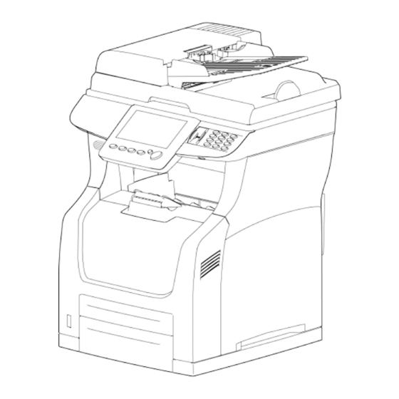
DN 3000329392 - 03 - 2 - GENERAL INFORMATION RESENTATION Sheet feeder scanner (ADF) 13 Paper tray 2 Adjustable paper guide 14 Toner cartridge access button Automatic document feeder 15 Chip card reader Original document output tray 16 Touch screen Paper stop 17 Access handle for the flatbed scanner Finger print reader... -
Page 7: G Eneral Description
- 3 - DN 3000329392 - 03 ENERAL DESCRIPTION These terminals are part of a range of multifunction office equipment. The product consist of a colour scanner with a 600 dpi resolution and a black and white printer with 1200 dpi resolution. The documents to be processed are read by means of a sheet feeder scanner using CCD sensor technology via the ADF (Automatic Document Feeder) or via the exposition window for bulky documents. -
Page 8: Characteristics
DN 3000329392 - 03 - 4 - CHARACTERISTICS HYSICAL CHARACTERISTICS Environment • Storage: • Operating : Multifunction : - The machine should not be exposed to - Temperature: -20 °C to 40 °C. direct sunlight. - Temperature changes: ≤10 °C/hour. - Power supply: 220-240 V - 50/60 Hz - 6 A. - Page 9 - 5 - DN 3000329392 - 03 Grey scale 16 bits Colour scale 48 bits (3 x 16)/pixel Paper size • Maximum width Letter • Maximum length Paper weight 60 to 105 g/m Capacity of document loading tray 70 sheets Acquisition time for black and white document •...
- Page 10 DN 3000329392 - 03 - 6 - Printing area 4 mm margins A4 : 208 x 289 mm Letter : 208 x 271 mm Duplex unit PaperSave in Printing Optional paper tray (2 max) Option Consumables management By smart card Fonts list Can be printed by menu "Report", "Fonts".
- Page 11 - 7 - DN 3000329392 - 03 Only one report for broadcast-list Yes (programmable) ECO PSTN sending ECO period On-hook dialling Reception without paper Yes (programmable) Multiple copying of received Fax Yes (1 to 99 copies) Deposit (for subscriber's polling) Multiple deposit (for several subscribers) Polling Fax TAD...
- Page 12 DN 3000329392 - 03 - 8 - WINS 2 servers access NetBIOS compatibility yes (2 names) SNTP compatibility Embedded Web Server Network scanner Scan To E-Mail Yes (SMTP) Scan To FTP Yes (FTP) Scan To Disk Yes (SMB) B&W Format PDF, TIFF, secured PDF (v1.1) Colour Format PDF, JPEG, secured PDF (v1.1)
- Page 13 - 9 - DN 3000329392 - 03 Speed (multicopy) cpm 35 / 24 / 35 / 24 cpm First copy- time from multipages 6 / 16/ 15 / 16 s Scan Resolution (HxV) dpi 600x600 / 600x600 / 600x600 / 600x600 Output resolution (HxV) dpi 300x300 / 600x600 / 600x600 /...
-
Page 14: Functioning
DN 3000329392 - 03 - 10 - FUNCTIONING The equipment is a Group 3 multifunction fax functioning in accordance with the UIT-T T30 recommendation. It consists of a black and white laser printer, a CCD (Charge Coupled Device) colour ADF scanner, a colour flatbed scanner, a front panel with a graphic colour screen equipped with a touchscreen and command keys (refer to the User Guide for a more complete description of the front panels). -
Page 15: M Ainboard
- 11 - DN 3000329392 - 03 • Set the main switches to the OFF position, • Disconnect all external interconnect leads (LAN, PTSN, USB), • Disconnect the mains lead. AINBOARD The CPU board is based on the ZORAN 4230 circuit which performs in particular the function of microprocessor. - Page 16 DN 3000329392 - 03 - 12 - Electronic architecture diagram : ELECTRONIC SYNOPTIC HFFv2 HFx Keyboard system Battery+ Timing LCD-TFT LCD Ctrl SPI2 System bus Quartz generator Touch screen Finger RX/TX GPIO print Eeprom SPI2 (on holder) Control Panel- Keypad DDR2 DDR2 DDR2...
- Page 17 - 13 - DN 3000329392 - 03 Architecture module :...
- Page 18 DN 3000329392 - 03 - 14 - Diagram of the Connector and Sensor Locations : Power motor supply & cable cable motor sensor P7102 P7103 P5200 P5120 P5300 P1202 Front panel USB SATA P4340 Smart card cable P1301 P4400 P3270 Front panel cable P4401 MAINBOARD UC...
- Page 19 - 15 - DN 3000329392 - 03 • P1202 : Smart Card interface Signal name Input / Description output CCAP_DETECT Smart card insertion detect CCAP_RESET* Smart card reset CCAP_CLK Smart card clock Ground CCAP_VCC Smart card power command CCAP_DIO Smart card data •...
- Page 20 DN 3000329392 - 03 - 16 - Ground Ground Ground Lvds_cko+ LVDS (Twisted wires) video clock Lvds_cko- Lvds_dso+ LVDS (Twisted wires) video data Lvds_dso- LVDS (Twisted wires) video data • P4100 : LAN Signal name Input / Description output Differential pair emitted on network Differential pair emitted on network Ground Ground...
- Page 21 - 17 - DN 3000329392 - 03 • P4400 : SATA DATA to HDD Signal name Input / Description output Ground SATA_TX+ SATA differential emitted data SATA_TX- SATA differential emitted data Ground SATA_RX- SATA differential received data SATA_RX+ SATA differential received data Ground •...
- Page 22 DN 3000329392 - 03 - 18 - • P5200 : Flat Bed motor cable Signal name Input / Description output FB_OUT2B Flat Bed phase 2B motor drive FB_OUT2A Flat Bed phase 2A motor drive FB_OUT1B Flat Bed phase 1B motor drive FB_OUT1A Flat Bed phase 1A motor drive FB_DETMOT...
- Page 23 - 19 - DN 3000329392 - 03 • P7102 : Power supply connector Signal name Input / Description output Ground P24V +24V Power supply • P7103 : Power supply connector Signal name Input / Description output Ground P3V3 +3V3 Power supply Ground P24V +24V Power supply...
- Page 24 DN 3000329392 - 03 - 20 - Ground SPK_MEZZ Speaker mezzanine Ground • P6100 : Printer interface Signal name Input / Description output HFF_VDATA<1> Data bus Ground HFF_VDATA<0> Data bus Ground HFF_VMREF +3.3V HFF_SLP* Sleep Command No connect Ground HFF_BD* Beam Detect Ground HFF_PPRDY*...
-
Page 25: Hffv2 Lcd
- 21 - DN 3000329392 - 03 2 LCD PANEL TOP EQUIPPED SSEMBLY The “HFFv2 LCD PANEL TOP EQUIPPED” is a Front panel Sub assembly, done to be managed and tested independently. The “HFFv2 LCD PANEL TOP EQUIPPED” is done from: •... - Page 26 DN 3000329392 - 03 - 22 - List of connectors : Connector Part Number Sexe Position number points Mainboard Male Straight Keypad Male Straight LCD panel video P101 Female Right angled LCD panel’s Touch P301 Female Right angled screen LCD panel Inverter P302 Male Right angled...
- Page 27 - 23 - DN 3000329392 - 03 Ground Ground Key_L2 Drive Keypad line 2 Key_L3 Drive Keypad line 3 Key_C1 Drive Keypad column 1 Key_C2 Drive Keypad column 2 Key_C3 Drive Keypad column 3 Key_C4 Drive Keypad column 4 Key_C5 Drive Keypad column 5 Key_C6 Drive Keypad column 6...
-
Page 28: Keypad Mezzanine Board
DN 3000329392 - 03 - 24 - Ground for logic circuit Alternated video signal input (Red) Alternated video signal input (Green) Alternated video signal input (Blue) AVDD +5V Supply voltage for analog circuit Ground for analog circuit P301 : Touch screen interface for LCD panel Signal name Input / Description... -
Page 29: Power Supply
- 25 - DN 3000329392 - 03 3.3.1 EYPAD BOARD The Keypad board manages the following functions: - 12 Digital Keypad touches, - LEDs for Finger print sensor light guide, - Connector to Keypad Mezzanine PCBA. Diagram of the Connector Locations To Keypad To Front panel mezzanine board... - Page 30 DN 3000329392 - 03 - 26 - P3V3 +3,3V power supply Ground Ground • P320 : Front panel interface from Keypad Signal name Input / Description output Ground FS_MISO SPI serial line – data output FS_MOSI SPI serial line – data input FS_SCK SPI serial line –...
- Page 31 - 27 - DN 3000329392 - 03 3.3.2 EYPAD EZZANINE BOARD The Keypad Mezzanine board integrates the finger print sensor. • P300 : Keypad interface from Mezanine Signal name Input / Description output Ground Ground P3V3 +3,3V power supply P3V3 +3,3V power supply Ground Ground...
-
Page 32: Power Supply
DN 3000329392 - 03 - 28 - POWER SUPPLY There are 3 power supply • Engine power supply board • LVPS module • DC/DC board The "engine power supply board" supplies 5v and 3v3 for the MFP. The "LVPS module" supplies 24V for the MFP in active mode and for the DC/DC board in sleep mode. The "DC/DC board"... -
Page 33: Crystals
- 29 - DN 3000329392 - 03 CRYSTALS 32K768Hz Real Time 32,768kHz Y1100 Controller Clock 24,576MHz Y1301 MODEM 25MHz Y4100 ETHERNET 24MHz Y4300 HUB USB 12MHz Y4400 SATA 12MHz Y1200 ZORAN RESET 3.3V MAX 6315 Zoran 4230C MR*/SRT RESET* RESET* HW_RESET* SATA SOFT_RESET*... -
Page 34: Standby Mode
DN 3000329392 - 03 - 30 - STANDBY MODE The HFFv2 product have 3 operational modes : • POWER OFF mode • ACTIVE mode • SLEEP mode POWER OFF mode: The POWER OFF mode is characterized by the HFFv2 Printer ON/OFF button in OFF position. The HFFv2 product is not powered. - Page 35 - 1 - IG 3000361032 - 01 INSTALLATION GUIDE CONTENTS INSTALLATION REQUIREMENTS PACE REQUIREMENTS LECTRICAL REQUIREMENTS 1.2.1 Mains 1.2.2 Telephone line NVIRONMENTAL CONDITIONS UNPACKING NPACKING THE TERMINAL NPACKING THE ADDITIONAL PAPER TRAY OPTION NSTALLING THE ERMINAL NSTALLING THE TONER CARTRIDGE NSTALLING THE PERFUME DIFFUSER CCORDING TO MODEL NSTALLING THE EXTENSION MEMORY...
- Page 36 IG 3000361032 - 01 - 2 - 5.2.8 Soft-switch 8 : Reserved 5.2.9 Soft-switch 9 : Approval + Communication applications 5.2.10Soft-switch 10 : Communications : locks/miscellaneous 5.2.11Soft-switch 11 : Retransmissions / Logs 5.2.12Soft-switch 12 : Quality 5.2.13Soft-switch 13 : Configuration internet 5.2.14Soft-switch 14 : Configuration internet 2 5.2.15Soft-switch 15 : Configuration internet 3 5.2.16Soft-switch 16 : Configuration internet 4...
-
Page 37: Installation Requirements
- 3 - IG 3000361032 - 01 INSTALLATION REQUIREMENTS PACE REQUIREMENTS The figure above shows the overall dimensions of the machine, optional accessories not included. LECTRICAL REQUIREMENTS 1.2.1 AINS Single-phase AC supply with earth, in conformance with the information on the label on the back of your MFP. -
Page 38: E Nvironmental Conditions
IG 3000361032 - 01 - 4 - NVIRONMENTAL CONDITIONS When selecting a location for the machine, the following points should be taken into account: • The telephone socket should be located no more than 2 meters away. • A standard single-phase mains socket with earth (rated in conformance with the information on the label on the back of the MFP) should be located no more than 2 meters away. -
Page 39: U Npacking The Additional Paper Tray
- 5 - IG 3000361032 - 01 • Take the duplex module out of its box. • Remove the protective side sections. • Remove the plastic bag from the module module. NPACKING THE ADDITIONAL PAPER TRAY OPTION • Take the additional tray out of its carton. •... -
Page 40: I Nstalling The Toner Cartridge
IG 3000361032 - 01 - 6 - • Insert the right and left tabs at the bottom of the duplex module into the holes at the back of the terminal and then align the top part of the duplex module with the terminal. Ensure that the connector of the duplex module is connected to the connector of the terminal. - Page 41 - 7 - IG 3000361032 - 01 • Lift the flatbed scanner then open the trap door to access the toner cartridge. • Unpack the new cartridge. Gently roll the cartridge 7 or 8 times to distribute the toner evenly inside the cartridge.
-
Page 42: I Nstalling The Perfume Diffuser
IG 3000361032 - 01 - 8 - • Close the the cartridge trap door then low the flatbed scanner. NSTALLING THE PERFUME DIFFUSER CCORDING TO MODEL The perfume unit is an option enabling you to install a perfume diffuser on the machine. When this option is installed and activated, the machine diffuses perfume every hour, and for a period of time defined by you. -
Page 43: I Nstalling The Extension Memory
- 9 - IG 3000361032 - 01 • Install the perfume diffuser on the terminal as showed in the illustration below. • Connect the power cord of the perfume diffuser in the connector of the terminal. • Once the perfume diffuser is installed, Press on MENU>SETTINGS>COMFORT>PERFUME and activate the perfume diffuser. - Page 44 IG 3000361032 - 01 - 10 - 2.6.2 NSTALLATION • Unscrew the fast screw at the right back of the printer then slide the housing. Screw • Uscrew the 12 screws (cross head) of the electronic cage.
- Page 45 - 11 - IG 3000361032 - 01 • Uscrew the 4 screws (Torx N°10) of the rear plate. • Unconnect the flat cable from the mainboard and unscrew the 2 screws (Torx N°10) of the second line modem. • Unconnect the 4 cables and uscrew the 3 screws (Torx N°10) of the PCB.
- Page 46 IG 3000361032 - 01 - 12 - • Disconnect the 2 cables of the hard disk (Data and power cable). • Unscrew the 4 screws (Torx N°10) of the HDD support (red arrows) and remove it. Remark(s): If the Second line modem was not installed, remove 2 more screws (yellow arrows).
-
Page 47: Loading Paper
- 13 - IG 3000361032 - 01 • Insert the memory extension. • Replace the different elements by performing the opposite action to that used to remove them. LOADING PAPER OADING PAPER IN THE PAPER TRAY The following section describes how to load paper into all trays of the multifonction. Remark(s): If the paper size is higher than A4, see §... - Page 48 IG 3000361032 - 01 - 14 - • Press down the media pressure plate to lock it into place. • Squeeze the length guide and slide it to the desired paper size. • Squeeze the right width guide and slide it to the desired paper size. •...
- Page 49 - 15 - IG 3000361032 - 01 • Close the lid of the paper tray. Make sure that the lid of the tray is correctly closed. • Replace the paper tray and push it completely into the terminal. • Define the size and type of paper that are used on the terminal. The terminal detect automaticaly the size of the standard paper.
- Page 50 IG 3000361032 - 01 - 16 - • Hold the grip of the paper tray and pull its extendable part to the front until it touches the desired paper size. • Squeeze the length guide and slide it to the desired paper size. •...
- Page 51 - 17 - IG 3000361032 - 01 • Close the lid of the paper tray. Make sure that the lid of the tray is correctly closed. • Replace the paper tray and push it completely into the terminal. • Define the size and type of paper that are used on the terminal. The terminal detect automaticaly the size of the standard paper.
-
Page 52: Installation
IG 3000361032 - 01 - 18 - WALL CONNECTIONS Caution - Make sure that the scanner's On/Off switch is "0" (Off). ELEPHONE AND AN CONNECTION • Connect the end of the telephone line lead to the telephone socket on the wall. •... -
Page 53: Start-Up And Software Configuration
- 19 - IG 3000361032 - 01 START-UP AND SOFTWARE CONFIGURATION NSTALLER PARAMETERS The purpose of these parameters is to adapt the MFP to specific user requirements and to the telecommunication standards of the country where the MFP is to be installed. At delivery, each MFP is programmed with the factory test configurations. -
Page 54: L Ist Of The Different Configurations
IG 3000361032 - 01 - 20 - (SW) IST OF THE DIFFERENT CONFIGURATIONS 5.2.1 1 : R SWITCH INGING AND AUTOMATIC PRINTING Value Designation SOS-CPT : Counters access # 0 : Without access # 1 : With access SOS-PAUSE : Type of signal, to warn user can dial when automatic dialling is running (except in waiting state at the beginning of dialling). - Page 55 - 21 - IG 3000361032 - 01 5.2.3 3 : L SWITCH INE CONFIGURATION Value Designation SOS-NIVEMI : Transmission level # 00 = 0 dBm # 01 = -1 dBm # 06 = -6 dBm # 0F = -15 dBm SOS- SEUILREC : Reception sensitivity Minimum value of threshold accepted # 0 = -43dB # 1 = -47 dB...
- Page 56 IG 3000361032 - 01 - 22 - 5.2.5 5 : L SWITCH OAD SPEAKER Value Designation Reserved Reserved Reserved Reserved SOS-HP : Line monitoring during fax comm. # 0 : No # 1 : Yes SOS- NIVHP : Power of Loud speaker (Bits 6, 7 and 8). Values # 000 : (zero) is ignored # 001 : Quiet level...
- Page 57 - 23 - IG 3000361032 - 01 5.2.10 S 10 : C SWITCH OMMUNICATIONS LOCKS MISCELLANEOUS Value Designation SOS-AFFVIT : Communication rate display # 0 : No the page number is displayed # 1 : Yes the comm. rate is displayed SOS-BTYPNUM : Access to impulse/DTMF parameter # 0 : Yes (Reserved) # 1 : No...
- Page 58 IG 3000361032 - 01 - 24 - 5.2.12 S 12 : Q SWITCH UALITY Value Designation SOS-GRIGNO: Width compression's algorithm # 0 : Without # 1 : With SOS-HMARGSUP: Width in Bit 2-3 Values : # 00 : 2 mm # 01 :3 mm # 10 : 4 mm # 11 : 5 mm...
- Page 59 - 25 - IG 3000361032 - 01 5.2.14 S 14 : C SWITCH ONFIGURATION INTERNET Value Designation SOS-CODNET : Document encoding type for Internet Comm. Values: # 00 : MH encoding # 01 : MR encoding # 10 : MMR encoding SOS-BRIDINET : Internet functional restrictions # 0 : No restriction # 1 : Internet functions restricted (no access to the menu...
- Page 60 IG 3000361032 - 01 - 26 - 5.2.16 S 16 : C SWITCH ONFIGURATION INTERNET Value Designation SOS-ACKNORECNET2 : Send a "message not understood" reply on reception of TIFF attachment # 0 : Send message # 1 : Do not send message SOS-MAILSWIMP : Printout when rerouting mailswitch # 0 : Printout # 1 : No printout...
- Page 61 - 27 - IG 3000361032 - 01 5.2.18 S 18 : C / UART SWITCH ODING RATE Value Designation SOS-CODMEM : Stored document encoding type Values: # 00 : RL encoding # 01 : MH encoding # 10 : MR encoding # 11 : MMR encoding SOS-CODCOM : COM negotiated encoding type Values:...
- Page 62 IG 3000361032 - 01 - 28 - 5.2.20 S 20 : H SWITCH ARDWARE MANAGMENT Value Designation SOS- FLTRPREAC : Anti-pre -accentuation external filter activation # 0 : No # 1 : Yes SOS- HPFRX : V21 HDLC V12 (HPFRX) filter detection activation # 0 : No # 1 : Yes Not used...
- Page 63 - 29 - IG 3000361032 - 01 5.2.22 S 22 : M SWITCH ISCELLANEOUS Value Designation SOS-DUREE-2100 : Transmission time of the 2100 modified for V34 reception Values: # 00 : 5 seconds # 01 : 4.5 seconds # 10 : 4 seconds # 11 : 3.5 seconds SOS-SORTIMP : Printing at the end of fax or Internet communications # 0 : Printing during comm.
- Page 64 IG 3000361032 - 01 - 30 - 5.2.24 S 24 : IEEE SWITCH ADDRESS Value Designation SOS-AOP-IEEE : Modification of the IEEE address by the AOP # 0 : Modification impossible # 1 : Modification possible Reserved Reserved Reserved Reserved Reserved Reserved Reserved...
- Page 65 - 31 - IG 3000361032 - 01 5.2.28 S 28 : M SWITCH ISCELLANEOUS Value Designation Activation of fax modification for DTS label # 0 : Missing # 1 : Present Carrier drop in ECP mode for DTS label # 0 : Missing # 1 : Present Reserved Reserved...
- Page 66 IG 3000361032 - 01 - 32 - 5.2.30 S 30 : M SWITCH ISCELLANEOUS Value Designation SOS- ECM2 : ECM use on line 2. # 0 : Without # 1 : With Reserved Reserved SOS- DI_NO_PAPER_JAM : Set if the printer driver stop its current work after a paper jam. Paper sheet can be lost.
- Page 67 - 33 - IG 3000361032 - 01 5.2.32 S 32 : M SWITCH ISCELLANEOUS Value Designation SOS- TRACE-ENABLE: # 0 : Trace disable # 1 : Trace enable SOS-TRACE-LEVEL: # 0 : Maximum level trace, used for developmentr. # 1 : Only error trace used for customer. SOS TTL_INCREASED: SOS to increase the TTL TTL (Time To Live): number of step between router.
- Page 68 IG 3000361032 - 01 - 34 - 5.2.34 S 34 : HDD SWITCH STORAGE Value Value Designation Stockage JPEG scanToMail/scanToSonar on HDD # 0 : On FLASH # 1 : On HDD Stockage JPEG scanToKey on HDD # 0 : On FLASH # 1 : On HDD Stockage JPEG scanToFile on HDD # 0 : On FLASH...
- Page 69 - 35 - IG 3000361032 - 01 5.2.36 S 36 : M SWITCH ISCELLANEOUS Value Designation RING_DETECT_LOW_FREQ (Ring detection) # 0 : Minimal Frequency for ring detection ( default case) # 1 : Minimal Frequency for square ring TAKACOM (bug 11308) SOS_STX_STOCK_MAILPDFBW_IN_MH (Saving transmited PDF B&W mails as MH or MMR) # 0 : Saving as MMR...
- Page 70 IG 3000361032 - 01 - 36 - 5.2.38 S 38 : S SWITCH PECIAL PRINT PC FEATURE Value Designation Formfeed treatment : (For software >=1.4.81E) Values : # 00 : Not Ignored (same behaviour as HP) # 01 : FF ignored after escape-E # 10 : TBD # 11 : FF ignored on blank page (same behaviour as Kyocera) Convert MMR to MH during PDF encapsulation .
-
Page 71: S Oftware Download
- 37 - IG 3000361032 - 01 OFTWARE DOWNLOAD Two methods can be used to update the software • by USB link • by local network There are 3 files to download: • the boot software, • the main software, •... - Page 72 IG 3000361032 - 01 - 38 - 5.3.2 OWNLOAD VIA LOCAL NETWORK This procedure requires an Ethernet cable and a PC equipped with a LAN card and a web browser (i.e Microsoft Internet Explorer release 6 or above, Mozilla Firefox (2.x or 3.x release or above ). •...
-
Page 73: Remote Readout (According To Model)
- 39 - IG 3000361032 - 01 REMOTE READOUT (ACCORDING TO MODEL) Caution - Before and after each intervention on a machine equipped with the Remote Readout option, perform a manual transmission of the Remote Readout parameters to the Server center, if the state of the machine allows it. -
Page 74: D Escription Of The Transmitted Data
IG 3000361032 - 01 - 40 - • The “threshold” criterion is based on the page thresholds entered in the remote readout menu accessed by means of the K MENU * 9559,"C EY SEQUENCE ONSUMABLES AUTOMATIC …" , "XXX " (XXX: means one kind of consumable ORDER BUTTON... - Page 75 - 41 - IG 3000361032 - 01 Field Type Char. / Num. Manual entry T_INIT_FOUR 0x69 long T_CPT_FOUR 0x6A long T_SEUIL_FOUR 0x6B long T_DATE_SEUIL_FOUR 0x6C char* T_DATE_CHG_FOUR 0x6D char* a. Fields "OPC" are used for Feeder Roller Scanner The values of the field Cause d'émission (TCAUSE_EMIS, reason for transmission) are the following: Interval (days) Manual send Toner Black...
-
Page 76: Remote Readout Report
IG 3000361032 - 01 - 42 - 6.3.2 EMOTE READOUT REPORT For each transmission a remote readout report is printed. It contains all the data that have been transmitted to the server in transparent mode. In the case of a transmission in fax mode, the fax that is received is identical to this report. - Page 77 - 43 - IG 3000361032 - 01 6.3.3 ESCRIPTION OF THE PARAMETERS The different fields shown in the report are described below. General information • Part number (TNO_23MIL): the 23M of the module managed by the server, entered by the installer;...
-
Page 78: R Eminders
IG 3000361032 - 01 - 44 - • Last remote order… (T_DATE_SEUIL_NOIR) : date of the last remote readout triggered by the toner criterion, or installation date if there has not been any previous remote readout; • (XXXX pages) (T_CPT_NOIR ) : value of the cumulative number of pages printed at the date of the previous remote readout triggered by the toner criterion (or 0 if there has not been any previous remote readout). -
Page 79: Saving Data By Network
- 45 - IG 3000361032 - 01 SAVING DATA BY NETWORK The machine allows to save/export parameters and addressbook from/to the PC. Operations are available from machine’s webSite. This mean allows tranfert from previous machine address book to the new one. Parameters Inport/export (file format: XML) Operations are available on the Settings tab of the website. -
Page 80: Packing And Transport Of The Machine
IG 3000361032 - 01 - 46 - PACKING AND TRANSPORT OF THE MACHINE When you need to transport the machine, always the original packing material. If you do not pack the machine correctly, you risk invalidating the warranty. • Set the mains switch of the machine to OFF (position 0). •... -
Page 81: Maintenance Guide
- 1 - MG 3000329394 - 03 MAINTENANCE GUIDE CONTENTS SCANNER AND COMMUNICATION REVENTIVE MAINTENANCE 1.1.1 Paper transport rollers 1.1.2 Paper separator module 1.1.3 CCD and Flatbed windows 1.1.4 Control panel keys, LCD panel and covers AINTENANCE 1.2.1 Periodical maintenance 1.2.2 Maintenance in workshop CANNING AND COMMUNICATION ERROR CODES 1.3.1 General codes... - Page 82 - 2 - MG 3000329394 - 03 1.11.4Procedure to use the makalu_210 software DISASSEMBLY/ASSEMBLY DESCRIPTION IST OF TOOLS IST OF WORKSHEETS LOCK DIAGRAM OF THE WORKSHEETS HFFV2 CABLING SPECIFICATION...
- Page 83 - 3 - MG 3000329394 - 03 SCANNER AND COMMUNICATION REVENTIVE MAINTENANCE To maintain the terminal in good working order, it is recommended to periodically perform the following operations: • Cleaning the paper transport rollers (document feeder, idler rollers). • Cleaning the paper separator. •...
- Page 84 - 4 - MG 3000329394 - 03 1.1.3 LATBED WINDOWS • Set the on/off switch to “O” (off). • Open the flatbed scanner cover. • Wipe the scanner windows with a lint-free cloth moistened with isopropyl alcohol, or with antistatic paper tissues as used for cleaning optical glass. Recommended interval: to be defined depending on utilization.
- Page 85 - 5 - MG 3000329394 - 03 Code 02 - Burnt number This code appears when all faxs sending trials have failed for this number (available only if SOS9 bit 6 is set to 1). Code 03 - Stopped by operator Communication stopped by the operator by pressing the key Code 04 - Programmed number invalid Invalid single-key or quick-dial number: check the number (for example: a delayed transmission has...
- Page 86 - 6 - MG 3000329394 - 03 Code 67 - Connection to SMTP server provider impossible Impossible to connect to the SMTP server to send mail: the service is temporarily not available. If this is a systematic error, verify the Internet e-mail and server settings. Code 68 - Connection to POP3 server impossible Impossible to connect to the POP3 server to receive mail: the service is temporarily not available.
- Page 87 - 7 - MG 3000329394 - 03 DMINISTRATOR FUNCTIONS AND SETTINGS 1.5.1 DMINISTRATOR FUNCTIONS Administrator functions are accessible by MENU * 1881 : Hidden Fonctions • RESTART : Reboot the machine. • STANDBY: Change the running state of the machine into sleeping mode. •...
- Page 88 - 8 - MG 3000329394 - 03 1.5.2 DMINISTRATOR SETTINGS Administrator setting are accessible by MENU * 9559 : Hidden Settings • FILE SYSTEM = EXT3 (cannot be changed) • ENCRYPTED DISK = YES (cannot be changed) • NUM REEMISSION = Allow to sent documents to an other fax machine in case of defective printer.
- Page 89 - 9 - MG 3000329394 - 03 BOARD REPLACEMENT 1.6.1 ROCEDURE Carry out the following procedure: • Carry out a remote readout (if the function is enabled), see chapter 6, in the Installation guide. • Back up the directory and the parameters via Web site, see chapter 7, in the Installation guide. •...
- Page 90 - 10 - MG 3000329394 - 03 ARD DISK ENCRYPTION HDD encryption is not available when the MFP is delivered from manufacturing line. If this feature is requested by the customer at installation, HDD Encryption has to be set before HDD formatting: If SOS 31 bit8 = 1 : encryption will be activated If SOS 31 bit8 = 0 : encryption will be not activated...
- Page 91 - 11 - MG 3000329394 - 03 OWNLOAD SOFTWARE INTO THE FRONT PANEL BOARD Aim of this chapter is to describe how to download software into PIC16F946 (Z1). It must be done only if new version is diffused. This component allows to manages touch panel, key matrix and leds of Front panel board and keypad board.
- Page 92 - 12 - MG 3000329394 - 03 RJ11 cable definition: This cable allows connecting the ICD2 module to the P3 connector. The table below allows an adaptation cord manufacturing.. This cable connect the ICD2 module to P3 connector. MPLAB ICD2 side Front Panel side (Run4 / Run5) Signal Pin (P3 Connector)
- Page 93 - 13 - MG 3000329394 - 03 1.9.4 INARY IMPORT Under MPLAB, import the file *.cof File → Import 1.9.5 IC PROGRAMMATION This step allows loading a FW into • Click Programmer → Program • Wait the end of the sequence Click Programmer →...
- Page 94 - 14 - MG 3000329394 - 03 1.11 CAN ORIGIN POSITION ADJUSTMENT 1.11.1 _210 AKALU SOFTWARE PRESENTATION This section explains how to set X and Y scanner threshold. It could be necessary in case of black line observed on the border of copies or scan. For this point, you need to use the Makalu_210 software.
- Page 95 - 15 - MG 3000329394 - 03 1.11.3 _210 AKALU SOFTWARE CONFIGURATION WITH FILE The program uses a file INI named "TestSAV.ini". Structure of this file respect Windows standard. In the event of error or corruption of this file it is enough to remove it. At next start the software will recreate it with the original configuration.
- Page 96 - 16 - MG 3000329394 - 03 A window with the installed driver opens • Select the scanner to configure in the list of available scanners • Click on Select The additional window closes • Click on Enter Test Mode If the HFFV2 is connected by USB link and if it is ready, the following screen appears : Green color and "Test Entry Pass"...
- Page 97 - 17 - MG 3000329394 - 03 The following window opens. The column Read Initial Value contains the current values of the scanner. X is the horizontal adjustment (length 297mm) Y is the vertical adjustment (width 210mm) Step 2 : If necessary you can change the Flat Bed scan setting •...
- Page 98 - 18 - MG 3000329394 - 03 At the end of the transfert, this window appears. The software provides values in the 2nd column • Click on Calculate for lines X FB and Y FB. • If the new values agree, click Write to validate the proposed settings. After writing, the new values are sent to the scanner and the new values appears in the first column.
- Page 99 - 19 - MG 3000329394 - 03 At the end of the transfert, this window appears: The software provides values in the 2nd column. • Click on Calculate for lines X ADF and Y ADF. • If the new values agree, click Write to validate the proposed settings. After writing, the new values are sent to the scanner and the new values appears in the first column.
- Page 100 - 20 - MG 3000329394 - 03 DISASSEMBLY/ASSEMBLY DESCRIPTION Remark(s): Before any disassembly or assembly operations, the machine must be switched off and all leads on the back of the MFP must be disconnected (phone line, LAN and mains leads). Remove the document trays and the paper feed tray. IST OF TOOLS •...
- Page 101 - 21 - MG 3000329394 - 03 LOCK DIAGRAM OF THE WORKSHEETS Trays (Worksheet D1) Feeder roller module, Accessibility to the Right front cover ADF scanner back door, ADF Left front cover Front cover and keypad electronic part (Worksheet D2) (Worksheet D9) and scanner covers (Worksheet D23)
- Page 102 - 22 - MG 3000329394 - 03 OBJECT:T Tools • None Preliminary steps • None Disassembly • Open the flatbed scanner cover. • Unstick the white panel located inside the flatbed scanner cover. • Clean the flap before to stick the new white panel. •...
- Page 103 - 23 - MG 3000329394 - 03 OBJECT:L EFT FRONT COVER Tools • None Preliminary steps • None Disassembly • Push from the bottom to the top at the bottom of the Left front cover in order to unclip it. •...
- Page 104 - 24 - MG 3000329394 - 03 OBJECT:R IGHT FRONT COVER WITH KEYPAD Tools • None Preliminary steps • None Disassembly • Push from the bottom to the top at the bottom of the Right front cover in order to unclip it. •...
- Page 105 - 25 - MG 3000329394 - 03 OBJECT:K EYPAD ASSEMBLY Tools • Screwdriver torx N°7 Preliminary steps • Worksheet D3 Disassembly • Unscrew the 8 screws. • Rotate a little the Keypad assembly.
- Page 106 - 26 - MG 3000329394 - 03 OBJECT:K EYPAD ASSEMBLY CONTINUED • Unconnect the cable (do not pull on wires) Assembly • Replace the different elements by performing the opposite action to that used to remove them.
- Page 107 - 27 - MG 3000329394 - 03 OBJECT:F RONT PANEL ASSEMBLY Tools • Screwdriver torx N°10 • Screwdriver torx N°20 Preliminary steps • Worksheet D2 to D4 Disassembly • Unscrew the screw ( Torx N°10) for the ground plate (picture). •...
- Page 108 - 28 - MG 3000329394 - 03 OBJECT:F RONT PANEL ASSEMBLY CONTINUED • Uscrew the 3 front screws (Torx N°20) of the scanner. • Unclip the bottom of the front panel assembly (pull at the bottom of the noze). • Pull (fron the bottom to the top) on the front scanner to unclip the front panel.
- Page 109 - 29 - MG 3000329394 - 03 OBJECT:F RONT PANEL ASSEMBLY CONTINUED • Rotate a little the front panel assembly and disconnect the 2 cables (USB and front panel cables Assembly • Replace the different elements by performing the opposite action to that used to remove them.
- Page 110 - 30 - MG 3000329394 - 03 OBJECT:USB FRONT Tools • Screwdriver torx N°7 Preliminary steps • Worksheet D5 Disassembly • Unscrew the 2 screws ( Torx N°7) of the front USB. Assembly • Replace the different elements by performing the opposite action to that used to remove them.
- Page 111 - 31 - MG 3000329394 - 03 OBJECT:F RONT PANEL Tools • Screwdriver torx N°7 Preliminary steps • Worksheet D5 Disassembly • Disconnect the 2 flat cables and and the LCD back light. • Uscrew the 5 screws (Torx N°7) of the PCB.
- Page 112 - 32 - MG 3000329394 - 03 OBJECT:F PCB ( RONT PANEL CONTINUED • Remove the PCB like in the picture. Assembly • Replace the different elements by performing the opposite action to that used to remove them.
- Page 113 - 33 - MG 3000329394 - 03 OBJECT:LCD SCREEN Tools • Screwdriver torx N°7 Preliminary steps • Worksheet D7 Disassembly • Remove the front panel keypad. • Remove the flat ferite (do not dammage the flex).
- Page 114 - 34 - MG 3000329394 - 03 OBJECT:LCD SCREEN CONTINUED • Remove the 4 ground spring. • Uscrew the 6 screws (Torx N°7) of the LCD holder. • Remove the LCD screen. Assembly • Replace the different elements by performing the opposite action to that used to remove them.
- Page 115 - 35 - MG 3000329394 - 03 OBJECT:ADF SCANNER Tools • Flat screwdriver (2x6mm) Preliminary steps • None Disassembly • Disconnect the ZenCube if this option is installed on the terminal. • To unclip the Interco trap, insert the flat screwdriver in the slop.
- Page 116 - 36 - MG 3000329394 - 03 OBJECT:ADF SCANNER CONTINUED • Rotate the Interco trap to remove it. Remark(s): Note the wire path of the ADF cable and the ground cable. • Disconnect the ground wire (faston connector).
- Page 117 - 37 - MG 3000329394 - 03 OBJECT:ADF SCANNER CONTINUED • Disconnect the ADF cable (plug). • Lift up the flap scanner equipped as shown on the illustration below. Apply manually a pressure at the base of both hinges, use a flat screwdriver if necessary. •...
- Page 118 - 38 - MG 3000329394 - 03 OBJECT:F , ADF EEDER ROLLER MODULE ACK DOOR AND SCANNER COVERS Tools • Torx hex screwdriver (Torx20) Preliminary steps • None. Disassembly • ADF cover - Stand at the left-hand side of the terminal. - Open the ADF cover.
- Page 119 - 39 - MG 3000329394 - 03 OBJECT:F , ADF EEDER ROLLER MODULE ACK DOOR AND SCANNER COVERS CONTINUED • ADF motor cover - Remove the Zen cube module if installed. - Unscrew the screw holding the motor cover. Motor cover - Press simultaneously on the left and the right of the ADF motor cover and lift it.
- Page 120 - 40 - MG 3000329394 - 03 OBJECT:I NPUT SCANNER ASSY INPUT PAPER ASSY AND FEEDER SHOE ASSY Tools • None. Preliminary steps • Open the ADF cover. Disassembly • Input scanner assy - Lift up the input scanner assy as shown on the illustration below. - Move the arms A and B away in the direction of the arrows.
- Page 121 - 41 - MG 3000329394 - 03 OBJECT:I NPUT SCANNER ASSY INPUT PAPER ASSY AND FEEDER SHOE ASSY CONTINUED • Feeder shoe assy - Unlock manually the feeder shoe assy (see arrow on the illustration below). - Remove the feeder shoe assy. Feeder shoes assy Assembly •...
- Page 122 - 42 - MG 3000329394 - 03 OBJECT:ADF , ADF MODULE UNIT FEEDER COVER AND MOTOR Tools • Torx hex screwdriver (Torx10) • Torx hex screwdriver (Torx20) • Phillips screwdriver Preliminary steps • Worksheet from D10 to D11 Disassembly • ADF module - Remove the four mouting screws of the ADF module (see arrows on the illustration below).
- Page 123 - 43 - MG 3000329394 - 03 OBJECT:ADF , ADF MODULE UNIT FEEDER COVER AND MOTOR CONTINUED - Unscrew the ejector ground plate (Torx 10). - Unscrew a little the tension holder to free the belt. - Replace the old Analysis roller belt by a new one. •...
- Page 124 - 44 - MG 3000329394 - 03 OBJECT:ADF , ADF MODULE UNIT FEEDER COVER AND MOTOR CONTINUED - Unscew a little bit the scew A and B. - Push the motor in direction showed by the red arrow and screw B. - Unscrew the tension motor frame assy (torx 10).
- Page 125 - 45 - MG 3000329394 - 03 OBJECT:ADF , ADF MODULE UNIT FEEDER COVER AND MOTOR CONTINUED - Remove the ADF feeder cover. Screws ADF feeder cover • ADF motor - Remove the two mounting screws of the motor. Motor mounting screws Motor cable - Disconnect the motor cable, if necessary.
- Page 126 - 46 - MG 3000329394 - 03 OBJECT:ADF , ADF MODULE UNIT FEEDER COVER AND MOTOR CONTINUED • White frame plate - Remove the ADF module. White frame plate - Apply a upward pressure on the white frame plate edge (A). - Hold and extract the white frame plate edge (A).
- Page 127 - 47 - MG 3000329394 - 03 OBJECT:F LATBED SCANNER Tools • Torx hex screwdriver (Torx20) Preliminary steps • Worksheet from D5 to D9 Disassembly • Uscrew the 5 screws (Torx N°20) of the upper scanner. • Unconnect the FB flat cable, FB ground cable and the FB motor.
- Page 128 - 48 - MG 3000329394 - 03 OBJECT:F LATBED SCANNER CONTINUED • Unconnect the FB in printer cable. • Remove the FB scanner. • Pay attention to not pull on cables or on the FFC. Assembly • Replace the different elements by performing the opposite action to that used to remove them.
- Page 129 - 49 - MG 3000329394 - 03 OBJECT:F LAP SCANNER EQUIPPED CANNER UPPER ASSY ENSION , CCD MOTOR EQUIPPED WITH BELT Tools • Torx hex screwdriver (Torx10) • Torx hex screwdriver (Torx20) • Phillips screwdriver • Flat screwdriver Preliminary steps •...
- Page 130 - 50 - MG 3000329394 - 03 OBJECT:F LAP SCANNER EQUIPPED CANNER UPPER ASSY ENSION , CCD MOTOR EQUIPPED WITH BELT - Unscrew the 5 torx 20 screws and remove the flat bed cover. - Move out the flat bed from the machine. - Cut the 2 grip rings Mounting screw - Unscrew the torx 10 screw.
- Page 131 - 51 - MG 3000329394 - 03 OBJECT:F LAP SCANNER EQUIPPED CANNER UPPER ASSY ENSION , CCD MOTOR EQUIPPED WITH BELT Remark(s): Don’t forget tune the tension of belt by unscrew and screwing the tension plate. Assembly • Replace the CCD equipped with belt by performing the opposite action to that used to remove it and use new grip ring.
- Page 132 - 52 - MG 3000329394 - 03 OBJECT:S MART CARD Tools • None Preliminary steps • Worksheet D5 Disassembly • Unclip the PCB. • Rotate the PCB then disconnet the cable. Assembly • Replace the different elements by performing the opposite action to that used to remove them.
- Page 133 - 53 - MG 3000329394 - 03 OBJECT:A CCESSIBILITY TO THE ELECTRONIC PART Tools • Screwdriver crosshead • Screwdriver torx N°10 Preliminary steps • None Disassembly • Unscrew the fast screw at the right back of the printer then slide the housing. •...
- Page 134 - 54 - MG 3000329394 - 03 OBJECT:A CCESSIBILITY TO THE ELECTRONIC PART CONTINUED • Uscrew the 4 screws (Torx N°10) of the rear plate. Assembly • Replace the different elements by performing the opposite action to that used to remove them.
- Page 135 - 55 - MG 3000329394 - 03 OBJECT:S ECOND LINE MODEM Tools • Screwdriver torx N°10 Preliminary steps • Worksheet D16 Disassembly • Unconnect the flat cable from the mainboard. • Uscrew the 2 screws (Torx N°10) of the second line modem. Assembly •...
- Page 136 - 56 - MG 3000329394 - 03 OBJECT:P OWER SUPPLY BOARD Tools • Screwdriver torx N°10 Preliminary steps • Worksheet D16 Disassembly • Unconnect the 4 cables. • Uscrew the 3 screws (Torx N°10) of the PCB. Assembly • Replace the different elements by performing the opposite action to that used to remove them.
- Page 137 - 57 - MG 3000329394 - 03 OBJECT:H ARD DISK Tools • Screwdriver torx N°10 Preliminary steps • Worksheet D17 and D18 Disassembly • Disconnect the 2 cables of the hard disk (Data and power cable).
- Page 138 - 58 - MG 3000329394 - 03 OBJECT:H ARD DISK CONTINUED • Unscrew the 4 screws (Torx N°10) of theHDD support (red arrows). Remark(s): If the Second line modem was not installed, remove 2 more screws (yellow arrows). Assembly • Replace the different elements by performing the opposite action to that used to remove them.
- Page 139 - 59 - MG 3000329394 - 03 OBJECT:CPU BOARD Tools • Screwdriver torx N°10 • Screwdriver 6 pans 5,5mm Preliminary steps • Worksheet D19 Disassembly • Disconnect all cables from the UC board.
- Page 140 - 60 - MG 3000329394 - 03 OBJECT:CPU BOARD CONTINUED • Uncrew the 2 screws with the screwdriver Torx N°10 (yellow arrows) and the 3 spacers with the Screwdriver 6 pans 5,5mm (red arrows). Assembly • Replace the different elements by performing the opposite action to that used to remove them.
- Page 141 - 61 - MG 3000329394 - 03 OBJECT:L OUDSPEAKER Tools • None Preliminary steps • Worksheet D8, D9 and D13 Disassembly • Unclip the loudpeaker by pushing on the clip. • Unconnect the loudspeaker cable from the UC, then remove the loudspeaker. Assembly •...
- Page 142 - 62 - MG 3000329394 - 03 OBJECT:LVPS Tools • Screwdriver torx N°10 Preliminary steps • Worksheet D16 Disassembly • Disconnect the LVPS cable from the DC-DC card. • Remove the right side cover: push on the 2 clips once the scannertray is in up position, then rotate the cover.
- Page 143 - 63 - MG 3000329394 - 03 OBJECT:LVPS ( CONTINUED • Pull the LVPS cable out of the electronic cage. • Unscrew the 4 screws (Torx N°10) of the LVPS holder. Diconnect the harness --> Yellow arrow. Assembly • Replace the different elements by performing the opposite action to that used to remove them.
- Page 144 - 64 - MG 3000329394 - 03 OBJECT:F RONT COVER Tools • Screwdriver torx N°10 Preliminary steps • None Disassembly • Open the consummable trap. • Remove the "top cover": pull vertically on the top cover to unclip.
- Page 145 - 65 - MG 3000329394 - 03 OBJECT:F RONT COVER CONTINUED • Uscrew the 2 screws (Torx N°10) of the front cover. • Rotate the front cover to desengage the 2 hooks. Assembly • Replace the different elements by performing the opposite action to that used to remove them.
- Page 146 - 66 - MG 3000329394 - 03 OBJECT:S CANNER TRAY Tools • Screwdriver torx N°7 • Screwdriver torx N°10 • Screwdriver torx N°25 Preliminary steps • Worsheets D20, D21, D22 and D23 Disassembly • Remove the right side cover: push on the 2 clips once the scannertray is in up position, then rotate the cover.
- Page 147 - 67 - MG 3000329394 - 03 OBJECT:S CANNER TRAY CONTINUED • Unscrew the screw (Torx N°10) of the "Wifi trap" and check is dongle are connected. Remove dongle if necessary. • Unscrew the screw (Torx N°25) of the "Hinge". •...
- Page 148 - 68 - MG 3000329394 - 03 OBJECT:S CANNER TRAY CONTINUED • Cut the 3 plastics link. • Note the position of all cables. Remove the 3 front cables --> must pass trhough the scanner tray holde. • Remove the 2 rear USB boards: unscrew the 4 screw (torx N°7).
- Page 149 - 69 - MG 3000329394 - 03 OBJECT:S CANNER TRAY CONTINUED • Note the position of all cables. Remove the 2 USB boards --> must pass trhough the scannertray holde. • Remove the ground cable: unscrew the screw (torx N°10). •...
- Page 150 - 70 - MG 3000329394 - 03 OBJECT:S CANNER TRAY CONTINUED • Note the position of all cables. Remove the 2 cables --> must pass trhough the scannertray holde. • Rotate by 90° the scanner tray.
- Page 151 - 71 - MG 3000329394 - 03 OBJECT:S CANNER TRAY CONTINUED • Slide the scannertray to desengage it from the interface. Assembly • Replace the different elements by performing the opposite action to that used to remove them.
- Page 152 - 72 - MG 3000329394 - 03 OBJECT:I NTERFACE Tools • Screwdriver torx N°10 • Screwdriver torx N°25 Preliminary steps • Worsheets D20, D21, D21, D23 and D24 Disassembly • Unscrew the screw (Torx N°25) of the "open button". • Unscrew the 2 screws at the back of the interface (Torx N°10).
- Page 153 - 73 - MG 3000329394 - 03 OBJECT:I NTERFACE CONTINUED • Unscrew the 7 screws that fix the interface to the printer (Torx N°10). Assembly • Replace the different elements by performing the opposite action to that used to remove them. Remark(s): Refer to the paragraph HFFv2 cabling specification P.74 to install correctly the wires.
- Page 154 - 74 - MG 3000329394 - 03 HFFV2 CABLING SPECIFICATION The specification describes the correct installation of the wires in the HFFv2 machine.
- Page 155 - 1 - NI/IPL 3000361031 - 01 ILLUSTRATED PART LIST CONTENTS PART LIST TABLES ABLE COLUMNS PARE PARTS ORDERING 1 / F LANCHE IGURE PRODUCT 2 / F LANCHE IGURE OUSING 3 / F LANCHE IGURE MODULE 4 / F LANCHE IGURE EYPAD...
- Page 156 - 2 - NI/IPL 3000361031 - 01 CONTENTS ETAIL OF SCANNER TRAY 15 / F LANCHE IGURE ETAIL OF SCANNER TRAY 16 / F LANCHE IGURE ETAIL OF FRONT PANEL 17 / F LANCHE IGURE ETAIL OF SUPPORT 18 / F LANCHE IGURE &...
- Page 157 - 3 - NI/IPL 3000361031 - 01 CONTENTS 31 / F LANCHE IGURE 500 2/2 APER EXIT 32 / F LANCHE IGURE & RAME DRIVE 33 / F LANCHE IGURE LECTRICAL 34 / F LANCHE IGURE PTION PAPER FEEDER 35 / F LANCHE IGURE UPLEX UNIT...
- Page 158 - 4 - NI/IPL 3000361031 - 01...
- Page 159 - 5 - NI/IPL 3000361031 - 01 PART LIST TABLES ABLE COLUMNS • ITEM NUMBER column: number of the item illustrated on the corresponding figure. Note 1: An item number preceded by a hyphen "-" is a non-illustrated item. Note 2: An item may be illustrated in a figure without being listed in the corresponding part list: such an article cannot be replaced other than by replacing the subassembly of which it is part.
- Page 160 - 6 - NI/IPL 3000361031 - 01 1 / F LANCHE IGURE...
- Page 161 - 7 - NI/IPL 3000361031 - 01 ITEM No. REFERENCE DESIGNATION 253086918 Duplex module 253074778 Base HFFv2 asm 253087139 Optional paper tray See §2 Line cord See §2 Power cord 253232817 Memory extension HFXv2 253217550 Zencube Diffuser HFx sunline 253235371 Grip ring tool 186205664 Grip ring DIAM11.5*DIAM4*0.2 THICK...
- Page 162 - 8 - NI/IPL 3000361031 - 01 2 / F LANCHE IGURE...
- Page 163 - 9 - NI/IPL 3000361031 - 01 ITEM No. REFERENCE DESIGNATION See §2 Left front panel See §2 Right front panel 253075126 Side cover right injected 186138694 Bottom right cover 253075134 Front cover injected 253075147 Top cover ASM 186138735 Paper guide 253075113 Side cover left injected 189976418...
- Page 164 - 10 - NI/IPL 3000361031 - 01 3 / F LANCHE IGURE...
- Page 165 - 11 - NI/IPL 3000361031 - 01 ITEM No. REFERENCE DESIGNATION 253032671 Flat scanner M&H ASM (see figure 18) 253075093 Interco trap injected 253125968 HFFv2 ADF in scanner cable not shielded LANCHE ADF MODULE IGURE...
- Page 166 - 12 - NI/IPL 3000361031 - 01 4 / F LANCHE IGURE...
- Page 167 - 13 - NI/IPL 3000361031 - 01 ITEM No. REFERENCE DESIGNATION 253070155 HFxv2 Keypad ASM 189976372 Screw torx 2x7 for plastic See §2 Keypad panel ASM 253074997 Screw torx 3x6mm 253127433 Ground spring keypad LANCHE KEYPAD IGURE...
- Page 168 - 14 - NI/IPL 3000361031 - 01 5 / F LANCHE IGURE...
- Page 169 - 15 - NI/IPL 3000361031 - 01 ITEM No. REFERENCE DESIGNATION 253090735 Screw torx 3x10mm 253058183 LCD front cover ASM Note : The software version of the Front panel must be at least Version E. See Administrator settings to read the version (PIC version parameter).
- Page 170 - 16 - NI/IPL 3000361031 - 01 6 / F LANCHE IGURE...
- Page 171 - 17 - NI/IPL 3000361031 - 01 ITEM No. REFERENCE DESIGNATION 253090748 Screw torx 4*12mm 253033053 Flatbed scanner H&M assy (see figure 23) 253096005 HFFv2 Flatbed ground cable 189955232 Flat cable LANCHE FLATBED ASM IGURE...
- Page 172 - 18 - NI/IPL 3000361031 - 01 7 / F LANCHE IGURE...
- Page 173 - 19 - NI/IPL 3000361031 - 01 ITEM No. REFERENCE DESIGNATION 253074864 Screw torx 6*12mm 253074851 Washer 6x12 253074822 Open button injected 253074843 Open button spring LANCHE OPEN BUTTON IGURE...
- Page 174 - 20 - NI/IPL 3000361031 - 01 8 / F LANCHE IGURE...
- Page 175 - 21 - NI/IPL 3000361031 - 01 ITEM No. REFERENCE DESIGNATION 253074893 Scanner tray ASM 191031847 BLOC.ALIM.SECTEUR 100-240V 24V/2A SP 253074872 LVPS holder injected 253090735 Screw torx 3x10mm LANCHE SCANNER TRAY ASM IGURE...
- Page 176 - 22 - NI/IPL 3000361031 - 01 9 / F LANCHE IGURE...
- Page 177 - 23 - NI/IPL 3000361031 - 01 ITEM No. REFERENCE DESIGNATION 253074819 Screw torx M3*8mm for metal 253074801 Interface injected 253123550 Screw torx M4*10 LANCHE INTERFACE IGURE...
- Page 178 - 24 - NI/IPL 3000361031 - 01 10 / F LANCHE IGURE...
- Page 179 - 25 - NI/IPL 3000361031 - 01 ITEM No. REFERENCE DESIGNATION 253074799 HDD support ASM 189976351 Screw self tapping M3x5mm Torx 253169530 Mylar protection 253052798 ref card Mezz. Modem 253074629 Mezz. Modem cord LANCHE HDD SUPPORT IGURE...
- Page 180 - 26 - NI/IPL 3000361031 - 01 11 / F LANCHE IGURE...
- Page 181 - 27 - NI/IPL 3000361031 - 01 ITEM No. REFERENCE DESIGNATION 189976351 Screw self tapping M3x5mm Torx 253058120 UC spacer See §2 Main PCB board programmed HFFV2 (SAV) LANCHE MAINBOARD IGURE...
- Page 182 - 28 - NI/IPL 3000361031 - 01 12 / F LANCHE IGURE...
- Page 183 - 29 - NI/IPL 3000361031 - 01 ITEM No. REFERENCE DESIGNATION 253058414 Rear plate 189976351 Screw self tapping M3x5mm Torx 253100768 Wire protection LANCHE BACK COVER IGURE...
- Page 184 - 30 - NI/IPL 3000361031 - 01 13 / F LANCHE IGURE...
- Page 185 - 31 - NI/IPL 3000361031 - 01 ITEM No. REFERENCE DESIGNATION 253114796 Trap holder Asm 253074819 Screw torx M3*8mm for metal 186138649 Trap See §2 Printer HFFv2 LANCHE TRAP HOLDER IGURE...
- Page 186 - 32 - NI/IPL 3000361031 - 01 14 / F LANCHE IGURE...
- Page 187 - 33 - NI/IPL 3000361031 - 01 ITEM No. REFERENCE DESIGNATION 253074997 Screw torx 3x6mm 253075072 Wifi-BT trap injected 253075085 Washer plastic 253088194 Washer D2D6 189976372 Screw torx 2x7 for plastic 189976108 Ferrite 186116833 Faston receiver PC2L25035LR(KST) 253108540 Ref Interco card 253074905 Scanner tray injected 253084625...
-
Page 188: Planche 15 / Figure
- 34 - NI/IPL 3000361031 - 01 15 / F LANCHE IGURE... - Page 189 - 35 - NI/IPL 3000361031 - 01 ITEM No. REFERENCE DESIGNATION 186113907 Screw2x6mm washer6x0.5 torx 253093640 USB Host Back 253083053 Ground plate to printer ground cable 253074997 Screw torx 3x6mm 253083053 HFFv2 ground plate to printer cable 253074968 Ground plate scanner tray 253074905 Scanner tray injected 253083029...
-
Page 190: Planche 16 / Figure
- 36 - NI/IPL 3000361031 - 01 16 / F LANCHE IGURE... - Page 191 - 37 - NI/IPL 3000361031 - 01 ITEM No. REFERENCE DESIGNATION 253110384 Ref USB Board 186113907 Screw2x6mm washer6x0.5 torx 253097114 Light guide injected 189976372 Screw torx 2x7 for plastic 253058266 Keypad front panel HFF-V2 253066903 Cable keypad LANCHE DETAIL OF FRONT PANEL IGURE...
-
Page 192: Planche 17 / Figure
- 38 - NI/IPL 3000361031 - 01 17 / F LANCHE IGURE... - Page 193 - 39 - NI/IPL 3000361031 - 01 ITEM No. REFERENCE DESIGNATION 253108582 Ref card DC-DC 189976351 Screw self tapping M3x5mm Torx 253083040 DC-DC 2 Wires Cables 253083032 DC-DC 5 Wires Cables DISQUE DUR 160GO 253284019 HDD SATA 2,5" FORMATE 253058133 HDD support LANCHE DETAIL OF HDD SUPPORT...
-
Page 194: Planche 18 / Figure
- 40 - NI/IPL 3000361031 - 01 18 / F LANCHE IGURE... - Page 195 - 41 - NI/IPL 3000361031 - 01 ITEM No. REFERENCE DESIGNATION 253029950 ADF right cover colored 253033029 Input scanner assy 253032684 FLAP scanner H&M equipped (see figure 19) 253063580 ADF MH equipped (see figure 20) 253029968 ADF left cover colored 253090748 Screw plastic 4x12 torx LANCHE...
-
Page 196: Planche 19 / Figure
- 42 - NI/IPL 3000361031 - 01 19 / F LANCHE IGURE... - Page 197 - 43 - NI/IPL 3000361031 - 01 ITEM No. REFERENCE DESIGNATION 253026582 Right hinge assembly 253090748 Screw plastic 4x12 torx 253026350 Left hinge assembly 253029294 Exit tray Makalu colored 253029252 Flap Makalu colored 253057107 Flap floam Makalu LANCHE FLAP SCANNER EQUIPPED IGURE...
-
Page 198: Planche 20 / Figure
- 44 - NI/IPL 3000361031 - 01 20 / F LANCHE IGURE... - Page 199 - 45 - NI/IPL 3000361031 - 01 ITEM No. REFERENCE DESIGNATION 253032811 ADF cover M&H assy (see figure 21) 253032788 Input paperway guide equipped (see figure 22) 253032725 ADF M&H assembly 189978272 Photointerrupter optic GP1S73 SP LANCHE ADF M&H EQUIPPED IGURE...
-
Page 200: Planche 21 / Figure
- 46 - NI/IPL 3000361031 - 01 21 / F LANCHE IGURE... - Page 201 - 47 - NI/IPL 3000361031 - 01 ITEM No. REFERENCE DESIGNATION 253029570 ADF cover M&H colored 253029591 Hook lever colored 252988296 Hook lever spring 252987968 Lock bearing spring 253029632 Lock bearing colored 253029588 Outside paper guide colored 253032840 Feeder roller module 253029629 Feeder stopper right colored 253029611...
-
Page 202: Planche 22 / Figure
- 48 - NI/IPL 3000361031 - 01 22 / F LANCHE IGURE... - Page 203 - 49 - NI/IPL 3000361031 - 01 ITEM No. REFERENCE DESIGNATION 253029504 Input paperway guide colored 253029517 Counter roller 3 sup.frame v 2 colored 253029538 Counter roller 3 sup colored 252989805 Counter roller shaft Makalu 252990770 Spring 1,5 N 253052032 Brush clip 253058055 Makalu brush...
-
Page 204: Planche 23 / Figure
- 50 - NI/IPL 3000361031 - 01 23 / F LANCHE IGURE... - Page 205 - 51 - NI/IPL 3000361031 - 01 ITEM No. REFERENCE DESIGNATION 253033186 Upper cover flatbed Makalu assy 253033264 Screw cover colored 253005658 Screw torx 4x12 mm 253033040 Bottom cover flatbed Makalu assy 253056431 CCD BOX PRIMAX EQUIPED 253104927 FLATBED MOTOR FDK -SMW35-EQUIPPED LANCHE FLATBED SCANNER H&M ASSY IGURE...
-
Page 206: Planche 24 / Figure
- 52 - NI/IPL 3000361031 - 01 (J244) 24 / F LANCHE IGURE... -
Page 207: Cover
- 53 - NI/IPL 3000361031 - 01 ITEM No. REFERENCE DESIGNATION 186138649 HFFV2 PRN COVER - KIT COVER OPEN SGM 186138652 HFFV2 PRN COVER - COVER REAR 45PPM 186138694 HFFV2 PRN COVER - COVER RIGHT J2 186138706 HFFV2 PRN COVER - COVER LEFT J2 186138735 HFFV2 PRN COVER - COVER STOPPER J2 186138673... -
Page 208: Planche 25 / Figure
- 54 - NI/IPL 3000361031 - 01 25 / F LANCHE IGURE... - Page 209 - 55 - NI/IPL 3000361031 - 01 ITEM No. REFERENCE DESIGNATION 186138769 HFFV2 PRN CST 150 - COVER CST HFFV2 PRN CST 150 - KIT ROLL ASSY 186138777 RETARD HFFV2 PRN CST 150 - HANDLE EXTENSION 186138798 186138818 HFFV2 PRN CST 150 - GUIDE END 150 186138821 HFFV2 PRN CST 150 - 150 PAPER CASSETTE 186138839...
-
Page 210: Planche 26 / Figure
- 56 - NI/IPL 3000361031 - 01 26 / F LANCHE IGURE... - Page 211 - 57 - NI/IPL 3000361031 - 01 ITEM No. REFERENCE DESIGNATION 186138850 HFFV2 PRN CST 550 - 550 PAPER CASSETTE 186138842 HFFV2 PRN CST 550 - GUIDE END 550 LANCHE PAPER CASSETTE 550 IGURE...
-
Page 212: Planche 27 / Figure
- 58 - NI/IPL 3000361031 - 01 (J220) (J240) (P220) (J22) (J245) (J241) (P242) (P244) (P243) (J242) (P241) (J243) 27 / F LANCHE IGURE... - Page 213 - 59 - NI/IPL 3000361031 - 01 ITEM No. REFERENCE DESIGNATION 186138863 HFFV2 PRN FDR 150 - KIT 150 FDR ASSY J2 186138871 HFFV2 PRN FDR 150 - ACTUATOR NO PAPER 186138884 HFFV2 PRN FDR 150 - GEAR IDLER NUDGER 186138892 HFFV2 PRN FDR 150 - GEAR NUDGER 186138904...
-
Page 214: Planche 28 / Figure
- 60 - NI/IPL 3000361031 - 01 (J260) (J26) (J246) (P247) (J248) (J247) 28 / F LANCHE IGURE... - Page 215 - 61 - NI/IPL 3000361031 - 01 ITEM No. REFERENCE DESIGNATION 186139034 HFFV2 PRN CST FDR - GUIDE TRAY RIGHT 186139042 HFFV2 PRN CST FDR - GUIDE TRAY LEFT 186139055 HFFV2 PRN CST FDR - LOCK CST L 186139063 HFFV2 PRN CST FDR - FEEDER2 ASSY 250-J2 LANCHE PAPER FEEDER 550 IGURE...
-
Page 216: Planche 29 / Figure
- 62 - NI/IPL 3000361031 - 01 (J270) (J170) (J140) (P131) (J160) (P141) (J31) (J15) (J16) (J13) (J14) (J17) (J150) (J45) (J141) (J47) (J4647) (J46) 29 / F LANCHE IGURE... -
Page 217: Xero
- 63 - NI/IPL 3000361031 - 01 ITEM No. REFERENCE DESIGNATION 186139076 HFFV2 PRN TNR ZONE - ROS ASSY 45-1200 HFFV2 PRN TNR ZONE - HARNESS ASSY ROS 186139097 186139104 HFFV2 PRN TNR ZONE - FAN SUB HFFV2 PRN TNR ZONE - GUIDE ASSY CRU L 186139117 HFFV2 PRN TNR ZONE - HARNESS ASSY 186139125... -
Page 218: Ni/Ipl 3000361031
- 64 - NI/IPL 3000361031 - 01 (J29) (J290) (J291) (J103) 30 / F LANCHE IGURE... - Page 219 - 65 - NI/IPL 3000361031 - 01 ITEM No. REFERENCE DESIGNATION 186139295 HFFV2 PRN PAP EXIT1 - 500 EXIT ASSY 45 186139401 HFFV2 PRN PAP EXIT1 - KIT CHUTE UP 550 HFFV2 PRN PAP EXIT1 - ACTUATR FULL 186139307 STACK 186139315 HFFV2 PRN PAP EXIT1 - ROLL EXIT HFFV2 PRN PAP EXIT1 - MOTOR ASSY EXIT...
- Page 220 - 66 - NI/IPL 3000361031 - 01 31 / F LANCHE IGURE...
- Page 221 - 67 - NI/IPL 3000361031 - 01 ITEM No. REFERENCE DESIGNATION 186139422 HFFV2 PRN PAP EXIT2 - ROLL PINCH FU 186143137 HFFV2 PRN PAP EXIT2 - STOPPER FSR 186139435 HFFV2 PRN PAP EXIT2 - COVER REAR 500 J2 186139443 HFFV2 PRN PAP EXIT2 - KIT COV REAR 500 LANCHE PAPER EXIT 500 2/2 IGURE...
- Page 222 - 68 - NI/IPL 3000361031 - 01 (J43) (J271) 32 / F LANCHE IGURE...
- Page 223 - 69 - NI/IPL 3000361031 - 01 ITEM No. REFERENCE DESIGNATION 186139456 HFFV2 PRN FRM DRV - MAIN MOTOR (J2) 186139464 HFFV2 PRN FRM DRV - GEAR ASSY HOUSING 186139477 HFFV2 PRN FRM DRV - SPRING RELEASE 186139485 HFFV2 PRN FRM DRV - GEAR 9 186139498 HFFV2 PRN FRM DRV - GEAR ASSY PLATE LANCHE...
- Page 224 - 70 - NI/IPL 3000361031 - 01 (J10) (J11) (J27) (J40) (J18) (J41) (P270) (J400) (J42) (P271) (J102) (PD2750A) (J1821A) (J20) (J22) (P3070) (P2083) (J24) (P221) (P245) (P248) (J30) (J44) (J48) (J480) 33 / F LANCHE IGURE...
- Page 225 - 71 - NI/IPL 3000361031 - 01 ITEM No. REFERENCE DESIGNATION 186139505 HFFV2 PRN ELEC - PWBA EXIT J2 See §2 HFFV2 PRN ELEC - PS LV J2 186139539 HFFV2 PRN ELEC - SWITCH ASSY EXIT J2 See §2 HFFV2 PRN ELEC - HRNS ASSY AC SGM 186139571 HFFV2 PRN ELEC - FFC ASSY ESS 186139592...
- Page 226 - 72 - NI/IPL 3000361031 - 01 (JD2083) (J85) (J82) (P820) (J83) (J80) (P855) (P801) (J820) (J81) (J802) (J810) (J800) (P802) (J801) (J84) (PD8483) 34 / F LANCHE IGURE...
- Page 227 - 73 - NI/IPL 3000361031 - 01 ITEM No. REFERENCE DESIGNATION 186139612 HFFV2 OPT FDR 550 - HARNESS ASSY FDR2 186139625 HFFV2 OPT FDR 550 - OPT ASSY SIZE 186139633 HFFV2 OPT FDR 550 - HRNS ASSY SIZE FDR1 186139646 HFFV2 OPT FDR 550 - FRAME CVR L A4 (MAT) 186139654 HFFV2 OPT FDR 550 - FOOT...
- Page 228 - 74 - NI/IPL 3000361031 - 01 (JD2750) (J50) (J53) (J51) (J54) (J530) (J52) (J520) 35 / F LANCHE IGURE...
- Page 229 - 75 - NI/IPL 3000361031 - 01 ITEM No. REFERENCE DESIGNATION 186139708 HFFV2 OPT DPLX - HSG UPPER ASSY 34PPM 186139716 HFFV2 OPT DPLX - SPRING PINCH 186139729 HFFV2 OPT DPLX - ROLL PINCH HFFV2 OPT DPLX - HARNESS ASSY DUP 186139737 34PPM 186139740...
- Page 230 NI/IPL 3000361031 - 01 - 76 -...
- Page 231 2.1 M HFFV2: ODEL BIZHUB FIGURE REPERE DESIGNATION REFERENCE Main PCB board programmed bizhub 43 (SAV) 253336243 Note : Formatting HDD must be done when the main board is changed. Telephone line cord 189721446 AC power cord 189641841 Left front panel...
- Page 232 PERSO 3000 348 280 - 02 - 2 -...
Need help?
Do you have a question about the bizhub 43 and is the answer not in the manual?
Questions and answers