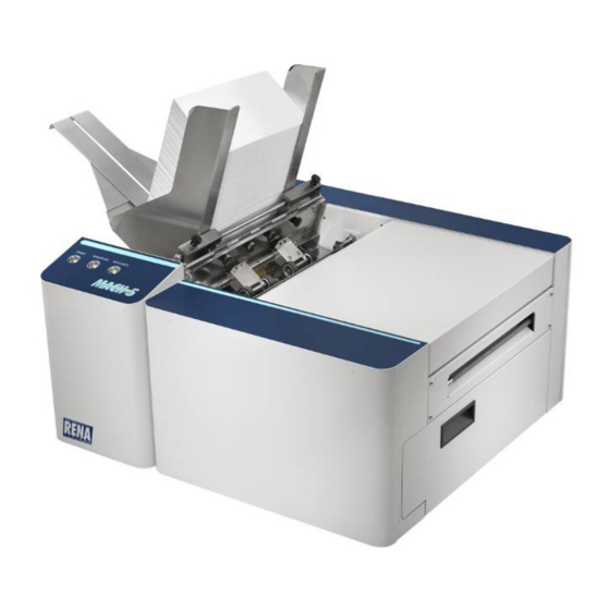
Rena MACH 5 Operator's Manual
Digital color printer
Hide thumbs
Also See for MACH 5:
- Service manual (186 pages) ,
- Operation manual (128 pages) ,
- Quick start manual (2 pages)
Table of Contents
Advertisement
Quick Links
Advertisement
Table of Contents

Related Manuals for Rena MACH 5


Summary of Contents for Rena MACH 5
- Page 1 MACH 5 DIGITAL COLOR PRINTER OPERATOR’S GUIDE Rev 6-20-11...
- Page 2 RENA Systems Inc. would like to Thank You for investing in our quality built products. Please record the following information for future reference: Model: Serial Number: Purchase Date: Purchased From: Dealer Name: Contact Name: Address: Address: Phone Number: Please take this opportunity to register your product.
-
Page 3: Table Of Contents
TABLE OF CONTENTS Table of Contents TABLE OF CONTENTS ..........................I SECTION 1 – GETTING ACQUAINTED ....................1 SAFETY PRECAUTIONS......................... 1 ............................... 2 RONT ..............................3 ........................... 4 RINT NGINE ........................5 EHIND THE SECTION 2 – INSTALLING THE PRINTER..................6 .......................... -
Page 4: Table Of Contents
S AND ARNINGS Alert Window Messages........................64 Toolbox System Status Messages......................65 APPENDIX A – RENA MACH 5 SPECIFICATIONS ................67 APPENDIX B – SUPPLIES AND OPTIONAL HARDWARE .............. 68 APPENDIX C – PREPARING PRINTER FOR TRANSPORT ............70 ..........................70 OCAL RELOCATION ...................... -
Page 5: Section 1 - Getting Acquainted
To the best of our knowledge, that information is accurate in all respects. However, neither RENA Systems, Inc. nor any of its agents or employees shall be responsible for any inaccuracies contained herein. -
Page 6: Front View
SECTION 1 GETTING ACQUAINTED Front View Exit Roller Cover – This cover plate must be removed to install the Service Station. Control Panel – Provides printer controls. See “Control Panel Functions” section. Side Guide Locking Knob – Used to secure the position of the side guide. Rear Media Support Guide –... -
Page 7: Rear View
SECTION 1 GETTING ACQUAINTED Rear View Main Power Switch, Receptacle and Fuse – Plug in AC power cord here. Switch turns main power on or off. Fuse provides over-current protection. Fuse rating: 2.5A, 250V, slow blow. CAUTION: Make sure power cord is disconnected from printer before checking/replacing fuse. WARNING: Press the ON/OFF Button, located on control panel, to properly shut-down the print engine. -
Page 8: Print Engine Area
SECTION 1 GETTING ACQUAINTED Print Engine Area Print Engine with printhead cartridge installed and printhead latch closed. Antistatic Brush Assembly – This assembly contains an antistatic brush that is used to help reduce static energy and remove paper dust from the media. This assembly also contains upper pressure rollers and fingers that help guide the paper into the print engine. -
Page 9: Behind The Ink Tank Door
SECTION 1 GETTING ACQUAINTED Behind the Ink Tank Door Ink Tank Securing Latches – Used to hold the Ink Tanks in the slots. NOTE: Please be sure that both sides, at the bottom part of the latch, are engaged. Ink Tanks – Five Ink Tanks are used in the printer. Cyan (C), Yellow (Y), Magenta (M), Black (K), Black (K) Ink Waste Tray –The purpose of this tray is to catch any waste ink produced by the system. -
Page 10: Section 2 - Installing The Printer
Choosing the Location The RENA Mach 5 should be placed on a sturdy, level, worktable or cabinet at least 9 inches from any walls. Protect the Mach 5 from excessive heat, dust, and moisture – avoid placing it in direct sunlight. -
Page 11: Unpacking
SECTION 2 INSTALLING THE PRINTER Unpacking Please refer to the unpacking sequence, shown below. NOTE: Packaging materials may vary slightly from what is shown below. Please save the packaging in a safe place, for possible future use. Two people will be required to safely lift the printer and place it onto a sturdy, level work table. IMPORTANT: WORK TABLE SURFACE MUST BE LEVEL! Save the Packaging for possible future use. -
Page 12: Accessory Box Contents
[K] Mach 5 Operation CD - contains printer software and pdf manual Note: Ink Tanks and Printhead Cartridges can be purchased through your local Rena Systems Dealer. To locate a Rena Systems Dealer in your area, please use the following link. http://www.renausa.com/dealer_locator_search.asp “Appendix... -
Page 13: Installing Media Guides
SECTION 2 INSTALLING THE PRINTER Installing Media Guides The screws needed to attach the side guides to the printer are located under the shipping tape in their respective positions. 1. Begin by installing the Media Registration Side Guide using the two screws [1] provided: 2. - Page 14 SECTION 2 INSTALLING THE PRINTER 3. Attach the Rear Media Support Guide using the knob [3] provided. The two outer holes in the guide fit over the socket head screws; as shown. 4. Install the desired Media Support Wedge using the mounting hardware [4];...
-
Page 15: Connecting The Printer
SECTION 2 INSTALLING THE PRINTER Connecting the Printer Connecting Power Check to make sure that he Main Power Switch [1] is in the OFF position. Connect the AC power cord to the printer’s receptacle [1]. Connect the other end of the AC power cord to a 115 – 230 volt AC, 50/60 Hz, grounded outlet. -
Page 16: Installing The Service Station
SECTION 2 INSTALLING THE PRINTER Installing the Service Station Due to the technical nature of this procedure; this process should only be performed by a qualified technical support person. This process is normally performed when the printer is first installed or when technical maintenance is needed on the printer. - Page 17 SECTION 2 INSTALLING THE PRINTER 5. Carefully remove the Service Station from its packaging. NOTE: Loose parts may fall out. Keep wiper roller side facing up, when removing the packaging. CAUTION! Make sure latches on the Wiper Roller are fully latched before installing the Service Station. Check the latch at each end of the wiper roller.
- Page 18 SECTION 2 INSTALLING THE PRINTER 8. Once the Ribbon Cable is properly connected to the Service Station Circuit Board; gently slide the Service Station, wiper roller end first, into the Service Station Slot until it stops. The Service Station fits into the slot immediately above the Ink Tank slots. NOTE: The Ink Tank Door must be open to perform this procedure.
- Page 19 SECTION 2 INSTALLING THE PRINTER 10. GENTLY push in on the Service Station with one hand, while slowly turning the “Large Gear” clockwise with the other hand. It should be easy to turn this gear and the service station should start to drive into the print engine squarely.
-
Page 20: Installing The Printer Software
During this process the M Series Driver and M Series Toolbox utility will be installed onto your computer system. NOTE: If you are updating the Mach 5 (M Series) printer software (printer driver and toolbox utility); please be sure to Uninstall the old software before installing the new software. Use the “Uninstall”... - Page 21 SECTION 2 INSTALLING THE PRINTER 5. When the Printer Connections window opens. Select the USB choice and then click Next>. NOTE: At the time of this manuals publication, information on connecting the printer via the Network (Ethernet) port was not available.
- Page 22 SECTION 2 INSTALLING THE PRINTER 9. When the “Finished software installation” window opens; uncheck the “Print Test Page” box. Since the printer still requires the installation of the ink tanks and the printhead cartridge; you do not want to print a test page at this time. Select if you want to set the printer as default or not.
-
Page 23: Install The Ink Tanks
INSTALLING THE PRINTER Install the Ink Tanks The Mach 5 printer uses five Ink Tanks (two Black, one Cyan, one Magenta, and one Yellow). The Ink Tank is a delicate, precision device. Handle with extreme care to avoid damage. Ink Tank Anatomy The ink used in this system may be harmful if swallowed. -
Page 24: Procedure (Installing The Ink Tanks)
SECTION 2 INSTALLING THE PRINTER PROCEDURE (Installing the Ink Tanks): This procedure assumes that you are installing Ink Tanks into a printer that doesn’t have any Ink Tanks installed. If you are replacing an empty Ink Tank, please refer to the “Replacing the Ink Tanks”... - Page 25 SECTION 2 INSTALLING THE PRINTER INSTALLATION TIP – To make sure the Ink Tank seats properly (septum needles penetrate the seals on the tank and the tank contacts make a good electrical connection with the system): Insert the Ink Tank firmly. Then pull the Ink Tank back out about an inch. Then push the Ink Tank back in, firmly.
-
Page 26: Installing The Printhead Cartridge
SECTION 2 INSTALLING THE PRINTER Installing the Printhead Cartridge The Mach 5 printer uses a single Memjet® printhead cartridge. The Printhead Cartridge is a delicate, precision device. Handle with extreme care to avoid damage and issues that could degrade print quality. -
Page 27: Procedure (Installing The Printhead)
SECTION 2 INSTALLING THE PRINTER CAUTION! • Hold the Printhead Cartridge by the handles ONLY. • DO NOT touch the ink couplings, nozzle surface or electrical contacts. • DO NOT unpack the Printhead Cartridge until the Printer is ready for installation. - Page 28 SECTION 2 INSTALLING THE PRINTER 6. Prepare the printhead cartridge. Carefully remove the Printhead Cartridge from the foil vacuum packaging. Tear at notch or cut end with scissors. CAUTION: DO NOT touch the ink couplings, printhead nozzle surface or electrical contacts. [A] Remove the protective plastic cover.
- Page 29 SECTION 2 INSTALLING THE PRINTER 7. To aid the cartridge priming process; wet the printhead nozzle surface, just before inserting the printhead. Wet a lint free cloth with deionized or distilled water and then wipe the entire length of the printhead nozzle surface with the wet cloth. NOTE: The use of deionized water is preferred;...
- Page 30 SECTION 2 INSTALLING THE PRINTER 11. Watch the Toolbox screen on your computer again. Notice that some of the information is in red. As the printer circulates ink and primes the system these fields should all turn black. This may take a few minutes. TIP: If the Printhead Cartridge fails to prime (ink doesn’t flow from all five color tubes at the non- operator side of the cartridge);...
-
Page 31: Section 3 - Operating The Printer
SECTION 3 OPERATING THE PRINTER Section 3 – Operating the Printer Control Panel Functions BUTTON FUNCTION(s) Press to power-up or power-down the print engine. Note: The Main Power Switch must be ON, to power-up the print engine. Powering-up: It takes approximately 45 seconds for the print engine to power-up; after pressing this button. -
Page 32: Printer Status Light Indicators
SECTION 3 OPERATING THE PRINTER Printer Status Light Indicators The lights on the three buttons, shown below, indicate the status of the printer. LEGEND (For the Status Light Indicator chart on the next page.): Description ON steady OFF steady Flashing (once per second) Fast Flash (twice per second) fast fast... - Page 33 SECTION 3 OPERATING THE PRINTER Printer Status Light Indicator Chart (see legend on previous page) PAPER PAUSE Printer Status ON/OFF Feeding Possible Solution RESUME CANCEL corresponding Toolbox message Print engine is powered-OFF In this condition, it is safe to turn the Main Power Switch OFF or ON. Print engine is powered-ON and ready Printer is Ready Print engine powering-down...
- Page 34 SECTION 3 OPERATING THE PRINTER Printer Status Light Indicator Chart (continued) PAPER PAUSE Printer Status ON/OFF Feeding Possible Solution RESUME CANCEL corresponding Toolbox message Printhead Missing Replace missing Printhead. Toolbox = PRINTHEAD_MISSING Remove Printhead Cartridge, wet print nozzles using deionized or Printhead Not Primed distilled water and re-install printhead cartridge.
-
Page 35: Setting Up The Feed
OPERATING THE PRINTER Setting up the Feed The Mach 5 printer is equipped with four sheet separators, two side guides, a rear media support guide and two different sized media support wedges. When properly adjusted these items will separate and guide the media so that only one piece of media is fed into the print engine at a time. - Page 36 SECTION 3 OPERATING THE PRINTER 3. Loosen the locking screws, located behind the sheet separators, and raise the separators. Then tighten the locking screws to hold the separators in the up position. 4. Place a single piece of the media, to be run, under the separators.
- Page 37 SECTION 3 OPERATING THE PRINTER 7. Adjust the position of the Rear Media Support Guide, so that it is centered under the width of your media. This guide slides side to side. 8. Adjust the position of the Media Support Wedge to accommodate the length of your media.
-
Page 38: Printer Driver And Toolbox Features
Printer Driver Properties The Printer Driver for the RENA Mach 5 works the same as any other Printer Driver for Windows. It does have some enhancements to help you maximize the ability of the printer to print variable addressed pieces quickly and efficiently. -
Page 39: Layout Tab
SECTION 3 OPERATING THE PRINTER • Borderless Print – Also known as “full-bleed” printing. Select this option to print to the edge of the page. The document is enlarged so the image extends slightly beyond the edge of the media. Take this into account when creating your document or artwork. -
Page 40: Media Tab
SECTION 3 OPERATING THE PRINTER Media Tab The Media tab provides the following features: • Position Adjustment – This feature will allow you to make small corrections in the horizontal and vertical position of the image. Horizontal Offset – allow you to set a plus or minus number. -
Page 41: Services Tab
SECTION 3 OPERATING THE PRINTER Services Tab The Services tab provides the following features: • Print Configuration Page – Prints out the current configuration of the printer including current Firmware version, Network Connection, printer Serial Number and more. • Print Demo Page – Prints color bands to check print quality and condition the printhead. -
Page 42: Using The M Series Toolbox Utility
SECTION 3 OPERATING THE PRINTER Using the M Series Toolbox Utility Once the M Series Driver and Software is installed you will have access to the “M Series Toolbox”. This Toolbox utility lets you monitor ink usage, perform diagnostic checks, print reports and run maintenance tasks on the printer from your computer. -
Page 43: User Interface
SECTION 3 OPERATING THE PRINTER User Interface The User Interface (Printer User Control) window opens by default when you start the Toolbox utility. From this screen you can Clear Errors, Cancel a Job, Reset the Job Counter, and Reset the Page Counter. You can also perform some maintenance and operating tasks such as: Clear Error –... -
Page 44: Ink Usage
SECTION 3 OPERATING THE PRINTER Ink Usage Provides the estimated volume of ink used, for each completed print job. - Does not include ink used during maintenance cycles - Pieces printed during the job will be separated by any maintenance cycles and manual pauses that occurred during the run. -
Page 45: Printing
6. Click on the “Print Demo Page” button to print the demo page (color bands) on the printer. Tip: You can use the “Color Purge PDF”, available from the Mach 5 Operation CD Menu, instead of the “Print Demo Page” feature from the printer driver. -
Page 46: Setting Up A Job In Ms Word® (2003)
SECTION 3 OPERATING THE PRINTER # 10 envelope (4.13” W x 9.5” L) feeding short side first: Select “Env. Com10 4 1/8 x 9 ½ in” in software and driver. Set top, bottom, left and right margins to minimum values, or any margin you require. - Page 47 SECTION 3 OPERATING THE PRINTER Envelope #10 (9.5” wide x 4.13” long) feeding flap first: The following procedure assumes that the printer has been setup to feed # 10 envelopes, flap first. Don’t forget to position the “Media Registration Side Guide” to the outer position. NOTE: When feeding a #10 envelope in this orientation you can not print the entire width of the envelope.
- Page 48 SECTION 3 OPERATING THE PRINTER Envelope #10 (4.13” wide x 9.5” long) feeding short side first: The following procedure assumes that the printer has been setup to feed # 10 envelopes, short side first. Don’t forget to position the “Media Registration Side Guide” to the inner position. NOTE: When feeding a #10 envelope in this orientation you can print the entire width and length of the envelope.
-
Page 49: Setting Up A Job In Satori Bulk Mailer
Printer Driver Limitation: Satori normally develops printer drivers for use with their software product. However; in the case of the Mach 5 printer; Satori has not developed a driver for this model. Therefore, you will need to use the features within the “M Series Driver” to control print quality, orientation, etc. - Page 50 Under Template Options select “Preview labels based on settings” and “Save settings as a new template”. Type a name (example: Mach 5 #10 Flap First Template) for your new template. Then click on Finished. 12. The template will be displayed for you to edit (add, remove, position data).
- Page 51 SECTION 3 OPERATING THE PRINTER 13. Add any additional items that you want printed to the “designer” screen. Drag and drop the items onto the layout, wherever you want them to be printed on the envelope. Click on Save. 14. Click on the "Go to Preview Mode" icon , located at the upper left-hand corner of the “designer”...
- Page 52 SECTION 3 OPERATING THE PRINTER 17. From the “M Series Printer Driver Properties” window; Click on the “Custom Sizes” button. The “Custom Media Size” window will open. Set the Width to 8.50 inches and the Height to 4.13 inches. Type a name into the “Media Name” windows (example: Custom #10 8.5W x 41.3H).
- Page 53 Under “Template Options” select “Preview labels based on settings” and “Save settings as a new template”. Type a name (example: Mach 5 #10 Short Edge First) for your new template. Then click on Finished. 10. The template will be displayed for you to edit (add, remove, position data).
- Page 54 SECTION 3 OPERATING THE PRINTER 11. Add any additional items that you want printed to the “designer” screen. Drag and drop the items onto the layout, wherever you want them to be printed on the envelope. Click on Save. 12. Click on the "Go to Preview Mode" icon , located at the upper left-hand corner of the “designer”...
- Page 55 SECTION 3 OPERATING THE PRINTER 14. From the “Mail Print Setup” window; Click on the “Advanced Settings” button. The “M Series Printer Driver Properties” window will open. Under Media Size select “Env. Com10 4 1/8 x 9 ½ in”. Under Orientation select Landscape Select your other desired choices Print quality (12 IPS Normal or 6 IPS Best).
-
Page 56: Section 4 - Operator Maintenance
Printhead care, clearing paper jams, replacing Ink Tanks, replacing Printhead Cartridge, replacing sheet separators. If printer maintenance or service is needed beyond the scope of what is covered in this section; please contact your Rena Systems Dealer for support. Ink Tank Storage and Handling •... - Page 57 SECTION 4 MAINTENANCE 5. Open the Ink Tank Door (hinged at bottom). 6. Unlock and Open the appropriate Ink Tank Securing Latch(s) [A]. 7. Remove the empty Ink Tank(s). 8. Remove the new Ink Tank(s) from the packaging. 9. Slide the new Ink Tank(s) (label side up) into their appropriate color slots. CYAN (C) YELLOW (Y) MAGENTA (M)
-
Page 58: Printhead Cartridge Storage And Handling
SECTION 4 MAINTENANCE Printhead Cartridge Storage and Handling Once installed, your printhead cartridge should remain in the printer until its useful life has expired. If you need to remove the printhead cartridge and store it for any specific reason: • Protect the printhead cartridge at all times from contamination by air-borne or surface contaminants such as dust or fibers. -
Page 59: Using The Clean Printhead Button
2. Clean the printhead nozzles. Once the printhead cartridge is removed; dampen a lint-free cloth (i.e. Rena Cartridge Wipes, PN 2023), with deionized or distilled water. Keep the printhead nozzle area facing down and gently wipe the printhead nozzle area, from end to end, in one direction and in one fluid motion. -
Page 60: Replacing The Printhead Cartridge
SECTION 4 MAINTENANCE Replacing the Printhead Cartridge The following procedure describes how to remove the Printhead Cartridge from the printer. WARNING! Never attempt to open the Printhead Latch manually, when in the closed/locked position. Severe damage will result. Use the Printhead Release Function from the Toolbox Utility on your PC or press the Printhead Latch Release button if a computer is not available. -
Page 61: Clearing Media Jams
2. Damaged media, such as dog-eared (turned down corners), curled or bowed media. 3. Media that is not stiff enough may not be usable. Media that meets Postal stiffness requirements for automated feeding is acceptable in the RENA Mach 5. 4. Media that is too thick for the printer. -
Page 62: Inspecting/Replacing The Ink Waste Tray
SECTION 4 MAINTENANCE Inspecting/Replacing the Ink Waste Tray The Ink Waste Tray is filled with an absorbent material, used to capture any ink that should drain from the system. 1. If the printer is on; press the ON/OFF button to power-down the print engine. Wait about 45 seconds until the system shuts down (all control panel lights will go off). -
Page 63: Replacing The Sheet Separators
SECTION 4 MAINTENANCE Replacing the Sheet Separators The sheet separators (90-103-09) insure separation of the pieces as they are being fed. If you experience double sheet feeding and cannot adjust the separators to prevent this, replace the separators. Replacing the sheet separators is not difficult; however if you don’t feel confident about doing this yourself;... - Page 64 SECTION 4 MAINTENANCE Cleaning WARNING THE PRINTER IS A PRECISION MACHINE THAT SHOULD BE CLEANED REGULARLY TO INSURE MANY YEARS OF SERVICE. BEFORE PERFORMING ANY MAINTENANCE, DISCONNECT THE MACHINE FROM ITS POWER SOURCE! DO NOT REMOVE SIDE COVERS! HIGH VOLTAGES PRESENT. Clean the Printer regularly to remove accumulated paper dust and ink.
-
Page 65: Section 5 - Troubleshooting Guide
The following troubleshooting guides are provided to assist you in solving any problems that might occur with the RENA Mach 5 Printer. We have tried to make them as complete as possible. The best advice we can offer is to make sure that the system is set up properly, plugged in, and that it has an adequate supply of ink before attempting to troubleshoot any problem. -
Page 66: The Printhead Cartridge
SECTION 5 TROUBLESHOOTING The Printhead Cartridge CONDITION PROBLEM SOLUTION Ink color channel mixing within the Refer to “Printhead Cartridge Mixed, mottled, muddy or distorted colors. printhead cartridge/nozzles. Conditioning”. Print Engine was opened to angle Do NOT open Print Engine greater than 60º. to angle greater than 60º. -
Page 67: The Printer
SECTION 5 TROUBLESHOOTING The Printer CONDITION PROBLEM SOLUTION Right edge of media being Media is hitting the limits inside Make sure Adjustable damaged as it travels through the print engine. Media Side Guide is at least 1/8” away from side frame. print engine area Use narrower stock. -
Page 68: Error's And Warnings
SECTION 5 TROUBLESHOOTING Error’s and Warnings Alert Window Messages Messages sent from the driver and displayed on PC screen in a small popup window. MESSAGE SOLUTION …. Ink Low Reorder Ink Example: Black Ink Low Reorder Ink Multiple Inks Low …. -
Page 69: Toolbox System Status Messages
SECTION 5 TROUBLESHOOTING Toolbox System Status Messages Displayed, in red, in the M Series Toolbox utility. SYSTEM STATUS PROBLEM SOLUTION PAPERPATH_FEED_TIME Out of Paper Load media into printer and press the No media is reaching the PAPER/RESUME button. print engine. If media is present;... - Page 70 SECTION 5 TROUBLESHOOTING Toolbox System Status Messages (continued) SYSTEM STATUS PROBLEM SOLUTION PRINTHEAD_MISSING No printhead installed or If just powered on, wait a minute; error printhead not making may clear by itself. proper connections. Install Printhead Cartridge. Remove and reinstall printhead. Replace printhead.
-
Page 71: Appendix A - Rena Mach 5 Specifications
APPENDIX B Appendix A – RENA Mach 5 Specifications SPEED (color or mono) Page Printing 8.5” x 11” Up to 3,600 per hour (1600 x 800 dpi @12 ips) No. 10 Envelopes Up to 7,500 per hour (1600 x 800 dpi @ 12 ips) Minimum: 3"... -
Page 72: Appendix B - Supplies And Optional Hardware
Optional Hardware Conveyor /Stacker Drop Tray NOTE: The use of a TB-390 conveyor with the Mach 5 printer is highly recommended. For this application; please be sure to order the Riser Legs for the TB-390 (part # TB-390 M5 FEET). - Page 73 Obtaining Supplies, Service and Support Please contact your local Rena dealer to obtain supplies, service and support for your printer. To locate a Rena dealer in your area, please click on the following link and fill out the form. http://www.renausa.com/dealer_locator_search.asp Service should only be performed by a qualified Rena service person.
-
Page 74: Appendix C - Preparing Printer For Transport
APPENDIX C Appendix C – Preparing Printer for Transport Please use this procedure if you ever need to transport the printer to a new location or ship the printer. Please refer to the appropriate sections in the manual for details on installing/removing items from the printer. - Page 75 APPENDIX C 10. Remove all five Ink Tanks. Be careful to avoid spills or stains during this process. Wrap each ink tank in a clean, lint-free, absorbent material and place them in a sealed plastic bag as a precaution against any spillages during transport. 11.
- Page 76 Cleaning, Feed Rollers & Forwarding Rollers..60 Clearing Media Jams ..........57 Contents, Accessory Box ..........8 M Series Toolbox Utility.......... 38 Control Panel ..............2 Mach 5 Operation CD ..........8 Control Panel Functions..........27 Main Power Switch ............ 3 Counter ...............3 Maintenance ............. 52 Media Registration Side Guide ......
- Page 77 INDEX Print Speed..............35 Sheet Separators ............3 Printer Driver Properties ...........34 Specifications ............67 Printer Driver, General Tab ........34 Supplies..............68 Printer Driver, Layout Tab........35 Support ..............69 Printer Driver, Services Tab........36, 37 Printer Status Light Indicators ......28, 29, 30 Printhead Cartridge ..........4, 8 Printhead Cartridge Conditioning ......41 Printhead Cartridge Protective Packaging....22...
- Page 78 RENA SYSTEMS INC. 136 Green Tree Road STE 140 Oaks, PA 19456-1069 Phone: (610) 650-9170 Fax: (610) 650-9171 E-Mail: support@renausa.com Web Site: www.renausa.com Copyright © 2011 All rights reserved...
Need help?
Do you have a question about the MACH 5 and is the answer not in the manual?
Questions and answers