Table of Contents
Advertisement
Advertisement
Chapters
Table of Contents
Troubleshooting

Related Manuals for Rena envelope imager III


Summary of Contents for Rena envelope imager III
- Page 2 Levér det brugte batteri tilbage tilleverandøren. Notice The information in this document is subject to change without notice. Rena Systems, Inc. makes no warranty of any kind with regard to the material contained herein. Rena Systems, Inc. will not be liable for incidental or consequential...
- Page 3 Introduction This manual is for the person who is new to the Rena Who is this Envelope Imager III Address Print Station and needs step-by- manual for? step instructions to setup and operate the printer. The appendix at the end of the manual has information for...
-
Page 4: Table Of Contents
Setting up a feeder to work with the printer ........3 - 1 Attaching the Riser Stand to the printer..........3 - 2 Connecting the Feeder Interface Cable to the Rena AF-500 .....3 - 2 Printer Menu Settings ................3 - 3 PRINTER TIPS Chapter 4 Setting the Fences for the media............4 - 1... - Page 5 SYMPTOMS & SOLUTIONS ............7 - 1 PRINTER MENUS APPENDIX A ENVELOPE IMAGER III MAIN MENU............A - 1 ENVELOPE IMAGER III SETUP MENU ..........A - 3 ENVELOPE IMAGER III SERVICE MENU..........A - 5 HEX CHART APPENDIX B HEX CHART....................B - 1 User’s Manual - Revision C...
-
Page 6: User's Manual - Revision C Section
PRINTER CONTROL COMMANDS APPENDIX C PCL COMMAND CODES................C - 1 CHARACTER SET APPENDIX D ENVELOPE IMAGER III CHARACTER SET...........D - 1 COMPUTER INTERFACE WIRING DIAGRAM APPENDIX E PARALLEL & T-11 CABLE WIRING DIAGRAM ........E - 1 PRINTING WITH SOFTWARE APPENDIX F SOFTWARE TABLE OF CONTENTS ............F - 1... -
Page 7: User's Manual - Revision C Section
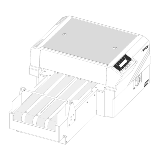
Parts of the Printer Envelope Imager III Parts & Locations User’s Manual - Revision C Section 1 - 1... -
Page 8: Setting Up The Printer
Setting up the Printer The following environmental considerations must be kept in Choosing a mind when selecting a location for the Address Printer. Doing Good otherwise may affect the operation and performance of the Location for Address Printer. 1. Place the printer close enough to the computer for the the Printer parallel cable to reach. -
Page 9: Connecting The Printer
Setting up the Printer Connecting Connect the Address Printer to the parallel port of the the Printer computer. The Parallel port is located on the rear of the printer near the power switch. Note: AB switches are To connect printer to the computer do the following steps. not recommended for operation with this 1. -
Page 10: Power On
The switch is located on the side of the printer next to the line cord receptacle. Press on the symbol "I" (ON) position. The printer LCD Ask your dealer for RENA Brand Ink: menu will display the initializing phrase... -
Page 11: Installing A Print Cartridge
Setting up the Printer CAUTION The ink in the print cartridge may be harmful if swallowed. Keep new and used cartridges out of reach of children. Discard empty print cartridges in the proper manner. 1. Remove the top cover. Installing a Print Cartridge 2. -
Page 12: Removing The Print Cartridge
Setting up the Printer When the Ink Low LED indicator is blinking the Print Removing Cartridges are nearly empty and have to be changed soon. Use the following steps to remove Print Cartridges. the Print See Cartridge Maintenance in Section 5-1 Cartridge 1. -
Page 13: Preparing The Media
Setting up the Printer Make certain all the necessary components of the printer are Preparing installed: the Media Is the printer plugged into a power outlet? • Does the printer have at least three print cartridges • installed in one of the Banks? Is the printer connected to the computer? •... -
Page 14: Media Types
Setting up the Printer The printer is designed to print on a variety of media with Media various finishes and coatings. The sharpness of the print Types quality will vary with different media types. Depending on how absorbent the media is, as well as, other qualities, the best results can be achieved using white wove bonded stock. -
Page 15: Running With A Power Feeder
Running with a Power Feeder Setting up a To use a feeder with the printer the setup requires two feeder to considerations: Use the following recommendations to help in setting up the work with printer. the printer. Media must go through the center of the Printer Align center of media here. -
Page 16: Attaching The Riser Stand To The Printer
Connecting Maximize the operation of the Rena AF-500 feeder and the Envelope Imager III by means of the Feeder Interface Cable the Feeder (Rena Part # 32-40215-001). The cable allows communication Interface between the printers’ Teleco port and the feeders’ External Run Input port. -
Page 17: Printer Menu Settings
Printer Menu Settings. Detailed information is found in section 6. Printer Menu Settings To effectively use the RENA AF-500 with the Envelope Imager III the following menu items have to be set as follows. Setup Menu: Feeder Signal: *ON/QUICK OFF; Signal Polarity: *ACTIVE OFF. -
Page 18: Operation Tips
11. Press the [Menu] button three times to exit the SETUP MENU. The normal display should appear. Operation Tips: Turn ON the Envelope Imager III first before turning • the power on for the AF-500 Feeder. Wait for the Envelope Imager III to fully initialize (Wait until On Line LED is lit.) before turning ON the AF-500. -
Page 19: Printer Tips
Printer Tips Knowing where the media will land on the printers’ Transport Setting the Belts is vital in achieving optimum results for the subsequent Fences for the setup and adjustments of the printer. Locate where the media will land on the printers Transport Belts. Make certain both Media fences are located all the way to the sides and are out of the path of the media. -
Page 20: Using The Entry Idler Roller Assembly
Printer Tips Using the Located between the Inner and Outer Fence Assembly are two Entry Roller Assemblies. Use the two Entry Idler Roller Entry Idler Assemblies when the media is thin and light weight. The Roller Entry Idler Roller Assemblies have been included to prevent the media from twisting and turning before the Inner and Assemblies Outer Fences have a chance of aligning the media and the... - Page 21 Printer Tips Different sizes and types of media call for unique settings of the Print Head Assemblies. To accommodate different sizes of media the Print Head Assemblies have to be raised or lowered until they touch the top of the media. Enough pressure has to be applied by the metal nose guides underneath the Print Head Assemblies to keep the media from moving around beneath the Print Cartridges while printing.
-
Page 22: Synchronizing New Print Cartridges In The Print Head Assembly
Printer Tips Each bank of three Print Cartridges has to be synchronized to print graphics, scaleable fonts or to justify the left edge of Synchronizing print. If the Print Cartridges are not synchronized anything new Print that requires two or three Print Cartridges to line up a left edge or to print next to each other may print to the left of one Cartridges in another or on top of each other. -
Page 23: Vertically Synchronizing A Bank Of Print Cartridges
Printer Tips When lines of print start to run on top of each other the Print Vertically Cartridges have to be synchronized vertically. Perform a Synchronizing Vertical adjustment whenever the center of the Test Pattern a Bank of isn’t a solid line. Work down from Head 1 on Bank A or Head 4 on Bank B. - Page 24 Printer Tips The example shows Print Cartridge #3 is to high. • Press the [+] plus or [ -] minus buttons to scroll through the Adjust Print menu options until the HEAD 3 UP DOWN option is displayed on the LCD panel. •...
-
Page 25: Horizontally Synchronizing A Bank Of Print Cartridges
Printer Tips When a line of print is split apart or the left edge of a block of Horizontally lines don’t line up with the left edge of the other lines the Print Synchronizing a Cartridges have to be synchronized horizontally. Perform a Horizontal adjustment whenever the large solid line and the Bank of Print set of 18 thin vertical lines do not form long vertical lines for... -
Page 26: Adjusting The Banks Apart
Printer Tips When the correct numeral is selected the large line and the set of 18 vertical lines form long vertical lines down the entire Bank A of Print Heads. Use the two Banks to print a return address and indicia on the Adjusting the top of a piece with the addressee’s on the bottom with a USPS Banks Apart... -
Page 27: Adjusting The Banks Together
Printer Tips Adjusting the The two Banks of print cartridges can be combined and used as one large block of print heads. This is best done for large Banks together fonts and big graphics or two-dimensional barcoding. To synchronize Banks A & B together, it requires mechanically adjusting the vertical position Head 1 Bank A Head 1 Bank A... -
Page 28: Synchronizing 3 Print Head Assemblies
Printer Tips The Print Head Assemblies (Banks A & B) need to be synchronized horizontally using the Adjust Print menu when the Test Pattern looks like one of the examples below. Head 1 Bank A Head 1 Bank A Head 2 Bank A Head 2 Bank A Head 3 Bank A Head 3 Bank A... - Page 29 Printer Tips • Press the [ -] minus (LESS) button to decrease the Move Bank B value on the LCD display. • Press the [Enter] button to select the desired value. An Asterisk (*) will appear in front of the new selection. •...
-
Page 30: Moving The Wipers
Printer Tips Moving the The Print Head Assemblies have several holes for relocating Nose the two narrow Guides. Move the Guides when synchronizing banks of print cartridges or when two or more banks of print Guides cartridges are printing near the same area or the Print Head Assembly has to print on or near the edge of a piece of media. -
Page 31: Performance Of The Printer
Performance Factors that Affect the Printers Performance of the Printer The Envelope Imager III is designed to give the best possible performance, but the speed can be affected by these factors. 1. The amount of memory available in the computer. -
Page 32: Cleaning And Maintaining The Printer
Cleaning and Maintaining the Printer Preventative The Envelope Imager III is designed for trouble free service with a minimal amount of care. Periodic cleaning of the Maintenance: Sensor, Transport Belts, Floor, Print Head Assemblies and cartridges will be necessary. CAUTION!! CLEAN SURFACES AND COVERS WITH PLAIN WATER. -
Page 33: Inkjet Cartridge Storage
To manually clean inkjet cartridges, we recommend using a Cartridge Wipe material (Rena part # 2023). This is a high quality, lint free material. We also suggest the use of distilled water in the cleaning process. Please note that the use of “abrasive materials”... -
Page 34: Cleaning The Photo Sensor Assembly
Cleaning and Maintaining the Printer With use, a film and/or dust builds up on the eye of the sensor Cleaning causing misfeeds of media. Periodically use compressed air to blow dust from the sensors. For caked on dust use a Q-tip to the Photo remove the dust from the eye of the sensor. -
Page 35: Cleaning The Transport Belts And Floor Assembly
Cleaning and Maintaining the Printer Ink may get sprayed on the Transport Belts or Floor Assembly Cleaning from all the purging, setting up and printing records, etc. An adequate amount of ink can accumulate on top of the Transport Belts to give the belts a glossy sheen. Use water to Transport dampen a soft cotton cloth to remove the ink from the Belts and... -
Page 36: Printer Menu System
Printer Menu System Front Panel Controls and LCD Display Use the controls on the Front Panel Assembly, consisting of six control buttons and an LCD display, to set up the Addressing Printer for proper operation with the computer system. Note the [+] &... -
Page 37: What Does The Display Show
Printer Menu System Exit the control panel menus. First press [Enter] to save a menu setting. [ENTER] Selects a menu option displayed on the control panel. Saves a new menu setting. An asterisk (*) will appear to the right of the value to indicate the new value has been entered. -
Page 38: Main Menu
Printer Menu System Main Menu Use this menu to choose the format and style of address printed and for information to assist in production. Selected menu options from a sub-menu will appear first in the list of options. Note: The printer driver overrides most control panel settings in the printer. Some of the control panel settings are also configured in the printer driver. -
Page 39: Print Quality
Printer Menu System available area used for printing. Note: Increasing the setting decreases the print area. The recommended setting for Distance From Top is 0.00. C. Line Spacing Automatic This sets the distance between lines of text. It is 3 lines / inch measured as the number of lines per inch of text. -
Page 40: Barcode
Printer Menu System Menu Items Selections Explanation A. Name Courier Select the style of the internal font to print the records with. San Serif Roman Baxter Dingbat Hancock Marina Quincy Silicon Springer Stencil Windmill B. Size 4 to 30 This item changes the size of the internal font. C. -
Page 41: Address Recovery
Printer Menu System recommended when generating a USPS barcode. The requirements to print a USPS barcode are shown in Appendix H. Menu Items Selections Explanation A. Location Above Address Select the US Postal Service Postnet Barcode options from the following selections: Below Address ABOVE ADDRESS: Prints the barcode in the address block above the first line of the address on... -
Page 42: Clear Counter
Printer Menu System B. Clear Memory Yes or No This option removes any data left in the data buffer. The alternative way to clear data from the Data Buffer is to press the [+] plus and [–] minus buttons simultaneously. 6. -
Page 43: Image Overlay
Printer Menu System 8. IMAGE OVERLAY This menu item is used in conjunction with the Overlay Printer Driver. Use this option to print redundant text or graphics in the same location on every piece. The Image Overlay option is best used for printing a company logo and return address. -
Page 44: Reset Ink Count
[Enter] button to reset the percent ink to 100%. Note : The calculation used to determine the percentage of ink available is based on the HP 51645A (or Rena C8842A) Print Cartridge. User’s Manual - Revision C Section 6 - 9... -
Page 45: Setup Menu
The Feeder Signal is to interface the Envelope Imager III with the AF-500 Feeder. The printer will give a signal to start the feeder when it receives one or more records. When the Stop On Feed Error option is turned ON and an error occurs the Envelope Imager III will stop the feeder. Menu Items... -
Page 46: Lines Per Address
Printer Menu System Menu Items Selections Explanation C. None This item disables the Feeder Signal option. Press the [Enter] button to select this item. D. On /Off Press the [Enter] This item activates the feeder whenever one or more Control button to select this records are in the buffer to be printed. -
Page 47: Hex Dump Mode
Printer Menu System CR=CR;LF=LF The typical software line termination is CR = CR; CR=CR+LF;LF=LF LF = LF. If your software is not typical then the CR=CR;LF=CR+LF Line Termination can be modified. CR=CR+LF;LF=CR+ 5. HEX DUMP MODE Utilize this option to print the raw ASCII data (HEX Code) that is being sent to the printer. Menu Items Selections Explanation... -
Page 48: Transport Speed
Printer Menu System Menu Items Selections Explanation ISO 16 PORTUGUE ISO 8859 ROMAN 8 WINDOWS LATIN 1 PC 8 CP 1250 B. Inch / This option converts the printer measurement Inch or Millimeters Millimeter system from inches to millimeters and vice versa. C. -
Page 49: Postal Bundle Break
Printer Menu System 8. POSTAL BUNDLE BRK (BREAK) This option will stop the printer for a few seconds before proceeding to print the rest of the records. This allows time for bundling the presorted records together and separate the bundle from the next batch of records being sent to the printer. -
Page 50: Pre-Purge
Printer Menu System Menu Items Selections Explanation C. Break Char 01 to 10 Set the number of occurrences the character or Count symbol must appear in succession before the printer can send a Postal Bundle Break signal. D. Pause Time 0.00 to 31.75 Set the length in seconds for the Feeder to sit idle before sending another piece of media. -
Page 51: Rom Revision
Capacity the percentage of ink used is calculated for the menu item 12. RESET INK COUNT. Note: The reservoir system (RENA C6119A) is nine times the volume of the C8842A ink cartridge. User’s Manual - Revision C Section 6 - 16... -
Page 52: Service Menu
Printer Menu System SERVICE MENU Use this menu for adjusting the print heads in each bank, the banks to each other, checking the transport and sensors and testing the display for proper functionality. The menu options that are preceded with a star or Asterisk (*) are the printers’... - Page 53 Printer Menu System E. Head 2 side 01 to 99 Use the options E through H to horizontally to side synchronize the individual Print Cartridges in Bank Press the [Test] button A or Bank B. F. Head 3 Side to print out a Test to Side Pattern.
- Page 54 Printer Menu System I. Bank A to 00.500 to 36.000 Use this option to set this distance between the Sensor Press the [Test] button sensor and the first head in bank A. to print out a Test Pattern. Check the Set each Bank of Print Heads to work together Test Pattern to (synchronized) or to work independently in different...
-
Page 55: Test System
Printer Menu System 2. TEST SYSTEM Use this option to check the mechanical and / or electrical operation of the Address Printer. Menu Items Selections Explanation Press the [Enter] The sensor is represented on the LCD by the button to select this lowercase letter p or the upper case letter P. -
Page 56: Troubleshooting & Diagnostics
Troubleshooting and Diagnostics Users Manual Symptoms & Solutions Chart SYMPTOM CAUSE SOLUTION No Power to printer. Check Power Cord. Call Service Representative. Nothing happens when power is switched on Fuse is blown Call Service Representative. Display Problem (Blank Bad LCD Call Service Representative. -
Page 57: Troubleshooting And Diagnostics
Print Quality Problems Ink Jet Cartridge problems Purge ink jet cartridge. (No print) Clean cartridge with RENA Tex Wipe lint-free cloth and distilled water. Change to a known good cartridge. Printing on belts or floor, Correct position with Address Layout Menu... - Page 58 (LED is blinking) through print. Dried ink clogging nozzles Purge Print Cartridge. on Print Cartridge. Clean cartridge with RENA Tex Wipe lint-free cloth and distilled water. Change to a known good cartridge. Pins bent or broken on Call Service Representative.
- Page 59 Troubleshooting and Diagnostics SYMPTOM CAUSE SOLUTION Print Quality Problems Main Menu setting of Bold Press Test Button. A bold Standard RENA (Unwanted Bolding) is enabled Systems Address is printed. Turn Bold setting off in Main Menu. ESC sequence turning bold Do a HEX Dump of the problem address.
- Page 60 Troubleshooting and Diagnostics SYMPTOM CAUSE SOLUTION Parallel Interface, printer is Bad data sent Turn printer off, then turn printer on and send not printing (Printer again. Halted) Bad communications Cable Replace parallel cable, maximum length 10 feet (304.8 cm) Bad main processor board Call Service Representative.
- Page 61 Troubleshooting and Diagnostics SYMPTOM CAUSE SOLUTION Print Head Error #1 Problems communicating Turn printer off then send again. If problem Bank(s) A B to both Bank A & B persists then call Service Representative. (Error Message) Different Print Head Problems communicating Turn printer off then send again.
-
Page 62: Envelope Imager Iii Main Menu
Appendix A • RENA Systems Envelope Imager III MAIN MENU Flow Chart ----MAIN MENU---- Address Layout DIST FROM LEFT +MORE DIST FROM LEFT +MORE 1. Address Layout A. Dist From Left *4.50 in -LESS *115 mm -LESS Address Layout DIST FROM TOP... - Page 63 Appendix A • RENA Systems Envelope Imager III MAIN MENU Flow Chart ----MAIN MENU---- ADDRESS RECOVERY 02: John P. Jones NONE TO RECOVER. A. Get Address Hit Recover ENTER to 5.Address Recovery ADDRESS RECOVERY Clear the +YES B. Clear Memory...
-
Page 64: Envelope Imager Iii Setup Menu
Appendix A • RENA Systems Envelope Imager III SETUP MENU Flow Chart ----SETUP MENU---- STOP ON FEED ERROR STOP ON FEED ERROR * On 1. Stop on Feed Err ----SETUP MENU---- FEEDER SIGNAL 2. Feeder Signal * ON/QUICK OFF FEEDER SIGNAL... - Page 65 Appendix A • RENA Systems Envelope Imager III SETUP MENU Flow Chart POSTAL BUNDLE BREAK ENABLE/DISABLE BREAK ENABLE/DISABLE BREAK ----SETUP MENU---- Enable/Disable Break *Off 8.Postal Bundle Brk POSTAL BUNDLE BREAK BREAK CHAR +NEXT *{*} -PREV Break Character POSTAL BUNDLE BREAK...
-
Page 66: Envelope Imager Iii Service Menu
Appendix A • RENA Systems Envelope Imager III SERVICE MENU Flow Chart ---SERVICE MENU--- BANK A MOVE HD 2 VERT Head 2 up down *294 press test -DOWN 1. Adjust Print BANK A MOVE HD 3 VERT Head 3 up down... -
Page 67: Hex Chart
Appendix B Hex Chart HEX CHART DECIMAL " & < > HEX CHART Example: The capital letter A is a HEX 41. Find the letter A on the above chart, and look towards the top of the chart (MSB) and locate the HEX number 4. Then look to the left side of the chart (LSB) and locate the Hex number 1. -
Page 68: Pcl Command Codes
Appendix C PCL Command Codes Introduction The Envelope Imager III emulates the listed PCL 5 printer command codes. The Envelope Imager III will virtually handle media as an HP1200 would using these printer commands. Additional printer commands have been added to allow control of special printer addressing functions and addressing needs. - Page 69 Appendix C PCL Command Codes PCL parameterized escape sequences Printer Feature Printer DEC Equivalent Description Command Equivalent Initialization Reset 1B 45 027 069 Defines reset conditions Hard Reset 1B 48 027 072 Performs reset plus clears all permanent macros, fonts, and address recovery buffer Page Control Page Size Default...
-
Page 70: Character Set
Appendix C PCL Command Codes PCL parameterized escape sequences Printer Feature Printer DEC Equivalent Description Command Equivalent Page Control Vertical Motion Index &l#C 1B 26 6C #..# 43 027 038 108 #..# 067 # of 1/48 inch (1/19 cm) (VMI) Line Spacing &l#D 1B 26 6C #..# 44... - Page 71 Appendix C PCL Command Codes PCL parameterized escape sequences Printer Feature Printer DEC Equivalent Description Command Equivalent Half Line Feed 1B 3D 027 061 Half of current VMI Line Termination &k#G 1B 26 6B 30 47 027 038 107 048 071 CR=CR, LF=LF, FF=FF 1B 26 6B 31 47 027 038 107 049 071...
- Page 72 Appendix C PCL Command Codes PCL parameterized escape sequences Printer Feature Printer DEC Equivalent Description Command Equivalent 1B 28 73 30 53 027 040 115 048 083 Upright 1B 28 73 31 53 027 040 115 049 083 Italic 1B 28 73 32 53 027 040 115 050 083 Expanded (150%) 1B 28 73 33 53...
- Page 73 Appendix C PCL Command Codes PCL parameterized escape sequences Printer Feature Printer DEC Equivalent Description Command Equivalent Font Selection (Primary) Typeface (s#T 1B 28 73 33 54 027 040 115 051 084 Courier 1B 28 73 34 54 027 040 115 052 084 San Serif 1B 28 73 35 54 027 040 115 053 084...
- Page 74 Appendix C PCL Command Codes PCL parameterized escape sequences Printer Feature Printer DEC Equivalent Description Command Equivalent Font Selection (Secondary) Height )s#V 1B 29 73 #..# 56 027 041 115 #..# 086 Point Size #/72 inch (1/28 Style )s#S 1B 29 73 30 53 027 041 115 048 083 Upright 1B 29 73 31 53...
- Page 75 Appendix C PCL Command Codes PCL parameterized escape sequences Printer Feature Printer DEC Equivalent Description Command Equivalent Font Selection (Secondary) Typeface )s#T 1B 29 73 33 54 027 041 115 051 084 Courier 1B 29 73 34 54 027 041 115 052 084 San Serif 1B 29 73 35 54 027 041 115 053 084...
- Page 76 Appendix C PCL Command Codes PCL parameterized escape sequences Printer Feature Printer DEC Equivalent Description Command Equivalent 1B 26 66 31 30 58 027 038 102 049 048 088 Make macro perm (last ID specified) Programming Hex Dump Mode ON 1B 59 027 089 Data printed as hex numbers,...
- Page 77 Appendix C PCL Command Codes PCL parameterized escape sequences Printer Feature Printer DEC Equivalent Description Command Equivalent Start Raster *r#A Graphics 1B 2A 72 30 41 027 042 114 048 065 Place to left most position 1B 2A 72 31 41 027 042 114 049 065 Place at current position End Raster...
- Page 78 PCL parameterized escape sequences To utilize the Envelope Imager III Address Printers internal bar-coding features, records are searched for a valid ZIP, ZIP + 4, Delivery Point Bar Code (DPBC) or DPBC with a check sum. For ZIP + 4 or a 11 digit DPBC, a checksum is computed for printing a USPS Postnet bar-code with framing bars.
- Page 79 Appendix C PCL Command Codes PCL parameterized escape sequences Printer Feature Printer Description Command Equivalent Equivalent Bar Code Bar Code - Vertical +b#V 1B 2B 62 #..# 56 027 043 098 #..# 086 VMI # in Decipoints (1/720 inch) from bottom of page to bottom of bar-code ZIP Code command +b#Znnn...
-
Page 80: Envelope Imager Iii Character Set
Appendix D Character Sets Envelope Imager III CHARACTER SET (Modeled after PC 850 Character Table) ░ └ <SP> Ç É á ð Ó ▒ ┴ Ð ± ü æ í ß ▓ ┬ " é Æ ó Ê Ô │... - Page 81 Appendix D Character Sets Envelope Imager III CHARACTER SET (Modeled after 8859 Latin Character Table) <SP> ° À Ð à ð ¡ ± Á Ñ á ñ ¢ Â Ò â ò " £ Ã Ó ã ó ¤ ´...
- Page 82 Appendix D Character Sets Envelope Imager III CHARACTER SET (Modeled after Roman -8 Character Table) <SP> ¯ â Å Á þ À ê î Ã Þ ô · " Â Ø ã È º û Æ Ð µ Ê Ç...
- Page 83 Appendix D Character Sets Envelope Imager III CHARACTER SET (Modeled after Windows 3.1 Latin Character Table) <SP> ° À Ð à ð ¡ ± Á Ñ á ñ ¢ Â ò " ‚ Ò â ƒ “ £ Ã Ó...
- Page 84 Appendix D Character Sets Envelope Imager III CHARACTER SET (Modeled after PC - 8 Character Table) ░ └ <SP> Ç É á ▒ ┴ ü æ í ± ▓ ┬ " é Æ ó │ ├ â ô ú ┤...
-
Page 85: Parallel Communication
Appendix E Accessory Cable & Parallel Interface The parallel interface port is a standard 36 pin Amphenol type Parallel with two metal wire retaining clips. Communication Pin # Signal Direction Description (Centronics Strobe A Low pulse causes the printer to read one byte of data Cable) Data 0 -Data7 Data lines. - Page 86 Appendix E Accessory Cable & Parallel Interface The Accessory Port allows the printer to control the start/stop function of the RENA AF-500 Feeder. Accessory Port Connect the printer to the feeder using the supplied interface cable to control the start-stop function of the AF-500 during the printing operation.
-
Page 87: Software Table Of Contents
Appendix F Printing with Software Software Table of Contents MICROSOFT WINDOWS A , & D ......3 PPLICATIONS OFTWARE RIVER NFORMATION Software Interface sample: Access 2000 for Window 98............4 Software Interface sample: Bulk Mailer + 4.20i for Windows ..........5 Software Interface sample: dBASE IV ver 1.0................7 Software interface sample: FILE EXPRESS ver. -
Page 88: Software Setup
Appendix F Printing with Software Software Setup This section will help in setting up the Address Printer to run programs in Windows 3.1 and DOS. Some assistance is given for use on the Apple and Macintosh. If you are using Windows 95 / 98 or Window NT 4.0 use the installation disk that is included in the accessories kit. -
Page 89: Microsoft Windows Applications Software Driver Information
Windows95/98 operating environment. 1. Click START ... SETTINGS... PRINTERS 2. Highlight the printer driver being used (i.e. the Envelope Imager III) 3. Click FILE ... PROPERTIES 4. Click on the DETAILS tab 5. Click on PORT SETTING ... make sure that none of the boxes are checked. -
Page 90: Software Interface Sample: Access 2000 For Window 98
Appendix F Printing with Software Access 2000 for Window 98 Software Interface sample: Select Open from the FILE menu. Select the .mdb database file or compatible database file. Select the OK button from the box. The window with the database name will appear. Select REPORTS from the side tab from the box. -
Page 91: Software Interface Sample: Bulk Mailer + 4.20I For Windows
Appendix F Printing with Software Bulk Mailer + 4.20i for Windows Software Interface sample: Installation: Follow the instructions in the User Manual to install Bulk Mailer. Select New from the File Menu. Follow the instructions in the Users Manual on how to enter your address information. When you are ready to print addresses;... - Page 92 Appendix F Printing with Software Select Print Direct from the File Menu. Select the Rena Imager III from the Print Direct Window (shown below). Rena Imager III Set the ADDRESS SETUP, located in the printer’s Setup Menu, to 8 lines.
-
Page 93: Software Interface Sample: Dbase Iv Ver 1.0
Appendix F Printing with Software dBASE IV ver 1.0 Software Interface sample: Upon entering dBASE, the dBASE Control Panel will be displayed. To Create a Label, move cursor to the labels column and select <create>. A label will be displayed on the screen. Press ALT &... -
Page 94: Software Interface Sample: File Express Ver. 5.1
FILE EXPRESS ver. 5.1 Software interface sample: When using FILE EXPRESS, A label must be defined in order to print your addresses on the Envelope Imager III. Select Label Printing (6) from the Main Menu. Select Design a New Label from Label Menu. - Page 95 Press F10 Select Record# Select Yes Set the Address Setup Menu on the Envelope Imager III to 7 lines. You are now ready to print addresses on your Envelope Imager III. User’s Manual - Revision C Section F - 9...
-
Page 96: Ibm Filing Assistant
Company: X Address: X City: + State: + Zip: + Using the Imager3 print spec, the program should now be able to output your address list to the Envelope Imager III. User’s Manual - Revision C Section F - 10... -
Page 97: Software Interface Sample: Microsoft Foxpro 2.6 For Windows
Follow the instructions in the User Manual to install Microsoft FoxPro. Choose Label from the Catalog Manager, then click on New. Rena The Create Label window will be displayed. Select the table or query you wish to create a label for. - Page 98 Appendix F Printing with Software The Label Wizard - Step 2 of 5 window will be displayed. Select Avery #5165 (8½ x 11) Click on Next. The Label Wizard - Step 3 of 5 window will be displayed. Select the fields you wish to include in your label.
- Page 99 Select Finish The Save As window will be displayed. Enter a filename for the label file. In our example, we have selected the filename Rena-test.lbx. Select OK. This will bring you back to the Catalog Manager. Select the file Rena-Test.
- Page 100 Appendix F Printing with Software Rena-Test Rena The Change Label window will be displayed. Click on Label Writer. Rena-Test Rena continued on next page User’s Manual - Revision C Section F - 14...
- Page 101 Appendix F Printing with Software The Microsoft FoxPro Label Edit window will be displayed. No fields will appear on the display, this is because the fields are located towards the bottom of the label. Click on the side scroll bar until you see the fields. Move the fields to the top left of the label, as shown below.
- Page 102 Appendix F Printing with Software Select Print from the Catalog Manager. The Catalog Manager Print window will be displayed. Select Printer as the destination. Click on OK. The Print window will be displayed. Click on Setup. Select the Generic/Text Only printer driver. Click on OK Set the ADDRESS SETUP, located in the printer’s Setup Menu, to 66 lines.
-
Page 103: Software Interface Sample: Lotus 123 Release 3.1+ For Dos
Set the ADDRESS SETUP in the Envelope Imager III menu to equal the number of lines each record. If page breaks are used, set ADDRESS SETUP in the Envelope Imager III menu to 1 line more than the number of lines in each record. -
Page 104: Multimate
Appendix F Printing with Software MULTIMATE Software interface sample: An address may be printed using Multimate Merge Print. Refer to MULTIMATE and create a merge file. The following is an example of a typical merge document for addressing: name title company address city... -
Page 105: Software Interface Sample: Mymaillist Ver. 1.9.7
Press F10 to Print. MyMailList is set to print to whatever printer you have connected to Parallel Port #1 (LPT1). If your Envelope Imager III is not connected to LPT1, press Ctrl-P to view the Printer Choice Menu, and select the correct port. -
Page 106: Software Interface Sample: Wordperfect 6.0
From the File menu, select Print/Fax Select DOS Text Printer Select Edit, and insure correct port is selected for the DOS Text Printer You may now print address lists on your Envelope Imager III Print Station. User’s Manual - Revision C Section F - 20... -
Page 107: Software Interface Sample: Wordstar For Dos Ver. 7.0
Once the page break is displayed, you can enter the next record. Repeat this process to enter all records. To Print: Set the Envelope Imager III Address Setup to eight (8) lines of address. Select Change Printer from the File Menu. Select Draft Printer. -
Page 108: Power Print For The Macintosh
• Select the LaserJet 4 printer driver. • Click on the serial port to which you have the Envelope Imager III connected, either the • modem (phone) or printer icon. NOTE: If you are connecting your printer cable to the printer port, Appletalk must be set to "inactive". - Page 109 Appendix F Printing with Software POWER PRINT for the MACINTOSH (Continued) Page Setup: • Select Show from the Layout menu, then select Non-Printable Area. • Set page width to 8.5 Inches (215.9 mm). • Set page length to 11 inches (279.4 mm). Measure the position of your address from the bottom edge of the paper, just as you would from the bottom edge of your mail piece.
-
Page 110: Computer Setup Sample: Ibm Mini's (System 34, 36, 38) & As400
IBM Mini's (System 34, 36, 38) & AS400 Computer setup sample: To use the Envelope Imager III with any IBM minicomputer or mainframe, it is necessary to interface through some kind of protocol converter. This may be one of two types of systems;... -
Page 111: Software Interface Sample: Microsoft Word For Windows Ver. 2.0
Appendix F Printing with Software MICROSOFT Software interface sample: WORD FOR WINDOWS ver. 2.0 Using you mouse Select FILE Inside the pull down menu for File, Select NEW Once New has been selected a pop up window will appear. Scroll through the available documents using the down arrow, Select MAILLABL Now Select OK Now a new pop up window appears called Mailing Labels Inside the Mailing Labels section, Select DOT MATRIX... -
Page 112: Software Interface Sample: Word97 For Windows 95
Appendix F Printing with Software Word97 for Windows 95 Software interface sample: Select Page Setup from the FILE menu. Select the Margins tab, and set ALL margins to zero (0) Select the Paper size tab, then select Custom from the Paper size text box. Set the page width to 4.2”... - Page 113 Click on the Ignore button. Select Page Layout from the VIEW menu, and your page should look similar to the example show below. RENA To print to the printer: Note: Make sure that the ADDRESS SETUP option in the Printer...
- Page 114 Appendix F Printing with Software To make a Mail Merge select Mail Merge from the TOOLS menu. The Mail Merge Helper window similar to the one to the right will appear. Select the Create pull down menu. Select “Form Letter”. Select the “Active Window”...
-
Page 115: Software Interface Sample: Word 2000 For Window 98
Appendix F Printing with Software Word 2000 for Window 98 Software Interface sample: Select New from the FILE menu. A NEW dialog box will appear on the screen. Select Blank Document from the GENERAL tab. Select Page Setup from he FILE menu. A PAGE SETUP dialog box will appear on the screen. - Page 116 Select the Merge or Merge to Printer icon from the toolbar. Your page should look similar to the last example below. The Print dialog box will appear. Make sure the Envelope Imager III is selected. Click OK to print. User’s Manual - Revision C...
-
Page 117: Technical Specifications
Appendix G Technical Specifications Shipping Dimensions and Weight of Printer Height: 13 inches 33.0 cm Length: 35 inches * 88.9 cm Depth: 25 inches 63.5 cm Weight: 103 lbs. (46.76 kg) including accessories. * Riser Stand: Adds 23 inches (58.4 cm) to overall length. Electrical Voltage: Selectable voltages: 100v, 120v, 220v, and 240v... - Page 118 The interface panel is located on the side of the machine. It contains the main power switch, the power receptacle and fuse. The interface ports (parallel and serial) are the interface connections between the Envelope Imager III and your computer. Connect the line cord from the printer receptacle to a properly grounded outlet box. Do not use an adapter plug.
-
Page 119: Us Mail Requirements
Appendix H US Mail Requirements DELIVERY POINT BAR CODE NAIC Certification This Address Printer is equipped with firmware for printing the United States Postal Service (USPS) Delivery Point Bar Code (DPBC). The printer is certified by the National Address Information Center (NAIC). -
Page 120: Planet Code Barcode
Appendix H US Mail Requirements PLANET Code Bar Code Postal Alpha-Numeric Encoding Technique (PLANET) provides features that are not currently available with the POSTNET barcode. PLANET bar codes are broken down to a list of planets. The following is a list of each planet and the applications supported by that planet’s particular PLANET bar code. -
Page 121: Ean / Ucc Requirements
Appendix I EAN / UCC Requirements EAN-13 / UPC-A Serial Shipping Barcode The printer has the ability to print a nominal sized EAN-13 and UPC shipping barcode in both the normal or invert mode. The barcode consists of the machine readable barcode on top and the human readable test beneath. - Page 122 Appendix J Glossary Glossary cable Wires that carry the information between the computer and the printer. Centronic parallel interface A device for connecting printers and other peripheral devices to a computer. It transmits a full byte at a time. Character A printable letter or symbol.
-
Page 123: Data Communications
Appendix J Glossary See characters per inch. data communications The sending of data from the computer to a peripheral device i.e. the printer. dots per inch The number of ink dots printed in one horizontal inch. The larger the number the better the resolution of print. -
Page 124: Interface Cable
Appendix J Glossary Grounded A electrical circuit that has a voltage of zero. Handshaking A method for the computer to communicate with peripheral devices to ensure complete transfer of information. hex dump A printer option that allows all the information and commands sent to the printer are printed as base 16 digits. - Page 125 Appendix J Glossary Online The printer will accept and respond to information sent from the computer. outline fonts Scaleable printer fonts. paper jam When media gets stuck in the printer. Parity An error checking method used when communicating between the computer and a peripheral device.
-
Page 126: Troubleshooting
Appendix J Glossary sans serif A font typeface that contains no serifs or finishing strokes on the top or bottom of the characters. scaleable fonts Outline printer fonts of characters and symbols that are stored in a mathematical form and are able to be enlarged or reduced.
Need help?
Do you have a question about the envelope imager III and is the answer not in the manual?
Questions and answers