Table of Contents
Advertisement
Quick Links
Advertisement
Table of Contents

Subscribe to Our Youtube Channel
Related Manuals for Cabletron Systems SmartSwitch 8000


Summary of Contents for Cabletron Systems SmartSwitch 8000
- Page 1 SmartSwitch Router 8000/8600 Getting Started Guide 9032552-06...
- Page 2 Printed in the United States of America Changes Cabletron Systems, Inc., reserves the right to make changes in specifications and other information contained in this document without prior notice. The reader should in all cases consult Cabletron Systems, Inc., to determine whether any such changes have been made.
-
Page 3: Regulatory Compliance Information
Regulatory Compliance Information Regulatory Compliance Information This product complies with the following: Safety UL 1950; CSA C22.2, No. 950; 73/23/EEC; EN 60950; IEC 950 Electromagnetic FCC Part 15; CSA C108.8; 89/336/EEC; EN 55022; EN 61000-3-2 Compatibility (EMC) EN 61000-3-3; EN 50082-1, AS/NZS 3548; VCCI V-3 Regulatory Compliance Statements FCC Compliance Statement This device complies with Part 15 of the FCC rules. - Page 4 Regulatory Compliance Statements NOTICE: The Industry Canada label identifies certified equipment. This certification means that the equipment meets telecommunications network protective, operational, and safety requirements as prescribed in the appropriate Terminal Equipment Technical Requirements document(s). The department does not guarantee the equipment will operate to the user’s satisfaction. Before installing this equipment, users should ensure that it is permissible to be connected to the facilities of the local telecommunications company.
- Page 5 Safety Information: Class 1 Laser Transceivers Safety Information: Class 1 Laser Transceivers This product may use Class 1 laser transceivers. Read the following safety information before installing or operating this product. The Class 1 laser transceivers use an optical feedback loop to maintain Class 1 operation limits. This control loop eliminates the need for maintenance checks or adjustments.
- Page 6 BEFORE OPENING OR UTILIZING THE ENCLOSED PRODUCT, CAREFULLY READ THIS LICENSE AGREEMENT. This document is an agreement (“Agreement”) between You, the end user, and Cabletron Systems, Inc. (“Cabletron”) that sets forth your rights and obligations with respect to the Cabletron software program (“Program”) in the package.
- Page 7 Cabletron Systems, Inc. Program License Agreement If the Program is exported from the United States pursuant to the License Exception TSR under the U.S. Export Administration Regulations, in addition to the restriction on transfer set forth in Sections 1 or 2 of this Agreement, You agree not to (i) reexport or release the Program, the source...
- Page 8 BEFORE OPENING OR UTILIZING THE ENCLOSED PRODUCT, CAREFULLY READ THIS LICENSE AGREEMENT. This document is an agreement (“Agreement”) between You, the end user, and Cabletron Systems Sales and Service, Inc. (“Cabletron”) that sets forth your rights and obligations with respect to the Cabletron software program (“Program”) in the package.
- Page 9 Cabletron Systems Sales and Service, Inc. Program License Agreement If the Program is exported from the United States pursuant to the License Exception TSR under the U.S. Export Administration Regulations, in addition to the restriction on transfer set forth in...
- Page 10 BEFORE OPENING OR UTILIZING THE ENCLOSED PRODUCT, CAREFULLY READ THIS LICENSE AGREEMENT. This document is an agreement (“Agreement”) between You, the end user, and Cabletron Systems Limited (“Cabletron”) that sets forth your rights and obligations with respect to the Cabletron software program (“Program”) in the package.
- Page 11 Cabletron Systems Limited Program License Agreement If the Program is exported from the United States pursuant to the License Exception TSR under the U.S. Export Administration Regulations, in addition to the restriction on transfer set forth in Sections 1 or 2 of this Agreement, You agree not to (i) reexport or release the Program, the source...
- Page 12 Declaration of Conformity Addendum Declaration of Conformity Addendum Application of Council Directive(s) 89/336/EEC 73/23/EEC Manufacturer’s Name Cabletron Systems, Inc. Manufacturer’s Address 35 Industrial Way PO Box 5005 Rochester, NH 03867 European Representative’s Name Mr. J. Solari European Representative’s Address Cabletron Systems Limited...
-
Page 13: Table Of Contents
Contents About This Guide ..................1 Who Should Read This Guide? ....................1 How to Use This Guide ......................1 Related Documentation......................2 Chapter 1: Features Overview ..............3 Specifications ..........................4 Features............................7 Hardware Overview ......................12 Chapter 2: Hardware Installation ............51 Safety Considerations ...................... - Page 14 Contents Appendix B: Technical Support ............111 Telephone Assistance......................1 11 FAX Service .......................... 111 Electronic Services....................... 111 Placing a Support Call ......................112 Hardware Warranty......................112 Software Warranty ......................112 Repair Services........................113 Appendix C: Cable Specifications............115 Index ...................... 119 SSR 8000/8600 Getting Started Guide...
-
Page 15: About This Guide
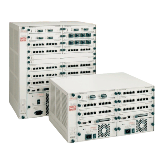
About This Guide This guide provides a general overview of the 8-slot and 16-slot SmartSwitch Router (SSR 8000 and SSR 8600) hardware and software features. It provides procedures for installing the SSR 8000 and SSR 8600 and setting them up for management using the CoreWatch software. -
Page 16: Related Documentation
“Technical Support” on support page 111 Related Documentation The Cabletron Systems documentation set includes the following items. Refer to these other documents to learn more about your product. For Information About... See the... Managing the SSR 8000 or SSR 8600 using CoreWatch User’s Manual and the... -
Page 17: Chapter 1: Features Overview
Chapter 1 Features Overview The 8-slot and 16-slot SSR (SSR 8000 and SSR 8600) provide non-blocking, wire-speed Layer-2 (switching), Layer-3 (routing) and Layer-4 (application) switching. This chapter provides a basic overview of the SmartSwitch Router (SSR) software and hardware feature set. -
Page 18: Specifications
Chapter 1: Features Overview Specifications The SSR provides wire-speed switching and full non-blocking throughput. The hardware provides wire-speed performance regardless of the performance monitoring, filtering, and Quality of Service (QoS) features enabled by the software. You do not need to accept performance compromises to run QoS or access control lists (ACLs). - Page 19 • Switching Fabric Modules (SSR 8600 only) • Power Supply (when redundant supply is installed and online) Load balancing/ • Cabletron Systems SmartTRUNK support sharing • Load Sharing Network Address Translation (LSNAT) Redundancy • Redundant and hot-swappable power supplies •...
- Page 20 Chapter 1: Features Overview This guide and other SSR documentation refers to the SSR’s Layer-2 (L2), Layer-3 (L3), and Layer-4 (L4) switching and routing. These layers are based on the International Standards Organization (ISO) 7-layer reference model. Here is an example of that model. The SSR operates within the layers that are not shaded.
-
Page 21: Features
Chapter 1: Features Overview Features This section describes the following SSR features: • Address-based and flow-based bridging • Port-based VLANs and protocol-based VLANs • IP and IPX routing • Layer-4 (application) switching • Security • Quality of Service (QoS) • Statistics •... -
Page 22: Port And Protocol Vlans
Chapter 1: Features Overview Port and Protocol VLANs The SSR supports the following types of Virtual LANs (VLANs): • Port-based VLANs – A port-based VLAN is a set of ports that comprises a Layer-2 broadcast domain. The SSR confines MAC-layer broadcasts to the ports in the VLAN on which the broadcast originates. - Page 23 Chapter 1: Features Overview IP Routing The SSR supports the following IP unicast routing protocols: • RIP v1 and RIP v2 • OSPF v2 • BGP 2,3,4 IP interfaces do not use a specific routing protocol by default. When you configure an interface for routing, you also specify the routing protocol the interface will use.
-
Page 24: Quality Of Service
Chapter 1: Features Overview the TCP or UDP source and destination port number (for IP) or the source and destination socket (for IPX). You can therefore manage and control individual flows between hosts on an individual application basis. A single host can have many individual Layer-4 entries in the SSR. For example, an IP host might have separate Layer-4 application entries for email, FTP, HTTP, and so on, or separate Layer-4 flow entries for specific email destinations and for specific FTP and Web connections. -
Page 25: Management Platforms
CLI to perform the basic setup procedures described in Chapter 3 of this guide. • CoreWatch – Cabletron Systems’s Java-based device management software. CoreWatch provides a graphical interface to the SSR, providing most of the same monitoring and control features as the CLI. •... -
Page 26: Hardware Overview
Chapter 1: Features Overview Hardware Overview This section describes the SSR hardware modules with which you will be working. Chapter 2 in this guide describes how to install the hardware. This section describes the following hardware: • Chassis, Backplane, and Fan module •... - Page 27 Chapter 1: Features Overview Figure 2 shows the front view of a fully loaded SSR 8600 chassis. The SSR 8600 chassis is similar to the SSR 8000 chassis, except for the following: • The chassis can contain up to 16 line cards. •...
-
Page 28: Fan Module
The line cards and Control Modules use the backplane to exchange control information and packets. The backplane is installed at the factory. Contact Cabletron Systems if you wish to replace the backplane. Fan Module The SSR contains a fan module to provide a cooling air flow across the Control Module(s) and line cards. - Page 29 Control Module includes 64MB of memory (in a 64MB DIMM). You can obtain SSR memory upgrade kits from Cabletron Systems to increase memory to 128MB (in a 128MB DIMM), 192MB (in one 64MB DIMM and one 128MB DIMM), or 256MB (in two 128MB DIMMs).
-
Page 30: Ac Power Supply
Chapter 1: Features Overview External Controls The Control Module has the following external controls. Where appropriate, this guide describes how to use the controls. • Male DB-9 Data Communications Equipment (DCE) port for serial connection from a management terminal. Use this port to establish a direct CLI connection to the SSR. The default baud rate is 9600. - Page 31 Chapter 1: Features Overview The SSR 8600 power supply is somewhat larger than the SSR 8000 power supply. Figure 7 shows the front view of an SSR 8600 AC power supply. SSR-PS-16 TO REMOVE POWER TO UNIT DISCONNECT ALL POWER SUPPLY CORDS 100-125V~ 10A 200-240V~ 6A 50/60 Hz...
-
Page 32: Dc Power Supply
Chapter 1: Features Overview DC Power Supply The SSR DC power supply delivers 3.3, 5, and 12 volts DC to the SSR’s Control Module(s), fan modules, and other components. A single DC power supply provides enough current to operate a fully-configured chassis. Figure 6 shows the front view of an SSR 8000 DC power supply. - Page 33 Chapter 1: Features Overview The SSR 8600 DC power supply has a five-terminal wiring block on the front panel, consisting of two positive(+) terminal, two negative(-) terminal and a safety ground. The DC supply is designed to be powered by a 48 Volt DC source. DC Power Supply Specifications The following table lists the physical specifications for the SSR’s DC Power Supplies.
-
Page 34: Line Cards
Chapter 1: Features Overview LEDs The SSR 8600 Switching Fabric module uses the following LEDs. Description Offline When lit, this amber LED indicates that the module is offline (powered off) and is ready for hot swap. The Offline LED also is lit briefly during a reboot or reset of the SSR and goes out as soon as the Control Module discovers and properly initializes the switching fabric module. - Page 35 Chapter 1: Features Overview SSR-GSX11-02 SSR-GSX21-02 SSR-GLX19-02 SSR-GLX29-02 SSR-GLX70-01 SSR-SERC-04 SSR-SERCE-04 SSR-HSSI-02 AA Cards SSR-HTX12-08-AA SSR-HTX22-08-AA SSR-HFX21-08-AA SSR-HFX29-08-AA SSR-GSX21-02-AA SSR-GLX29-02-AA SSR-GLX70-01-AA SSR-SERC-04-AA SSR-SERCE-04-AA SSR-HSSI-02-AA T-Series Cards SSR-POS21-04 SSR-POS29-04 SSR-POS31-02 SSR-POS39-02 SSR-ATM29-02 SSR-HTX32-16 SSR-GSX31-02 SSR-GLX39-02 SSR-GTX32-02 SSR 8000/8600 Getting Started Guide...
- Page 36 Chapter 1: Features Overview Note: The ATM line card supports a various number of physical interfaces (PHY). Different PHYs can be installed into the ATM line card. The PHY types supported are: DS-3/T-3, E-3, T-1, E-1, OC-3c MMF, OC-3c SMF, and OC-3c UTP. The T-Series line cards are considered the next generation line card family for the SSR Smart Switch Routers.
- Page 37 Chapter 1: Features Overview Cabling and Connector Specifications The following table lists the media specifications for the 10/100Base-TX line card. Port type Specification 10Base-T • 802.3 standard • RJ-45 connector wired as Media Data Interface Crossed (MDIX); “10/100Base-TX Line Card” on page 72 for pin assignments •...
- Page 38 Chapter 1: Features Overview 10/100Base-TX (T-Series) Line Card The 10/100Base-TX 16-Port line card contains 16 independent Ethernet ports. Each port senses whether it is connected to a 10-Mbps segment or a 100-Mbps segment and automatically configures itself as a 10Base-T or 100Base-TX port. Figure 10 shows the front panel of the 10/100Base-TX line card.
- Page 39 Chapter 1: Features Overview LEDs The 10/100Base-TX (T-Series) line card uses the following LEDs. Description Offline When lit, this amber LED on the left side of the line card indicates that the line card is offline (powered off) and is ready for hot swap.
- Page 40 Chapter 1: Features Overview Cabling and Connector Specifications The following table lists the media specifications for the 100Base-FX line card. Port type Specification 100Base-FX • 802.3u standard • SC-style Media Interface Connector (MIC); either connection pin in the MIC can be used for transmit or receive; see “1000Base-SX Line Card and 100Base-FX Line Card”...
- Page 41 Chapter 1: Features Overview 100Base-FX Line Card (Singlemode Fiber-optic Cable) The SMF 100Base-FX line card uses singlemode fiber-optic cable (SMF) to connect to the network. Figure 12 shows the front panel of the SMF 100Base-FX line card. SSR-HFX29-08 100BASE-FX Offline Swap Online 100 BASE-FX ports...
- Page 42 Chapter 1: Features Overview LEDs The 100Base-FX line card uses the following LEDs. Description Offline When lit, this amber LED on the left side of the line card indicates that the line card is offline (powered off) but is ready for hot swap.
- Page 43 Chapter 1: Features Overview Figure 14 shows the front panel of the 1000Base-SX (T-Series) line card. SRR-GSX31-02 1000BASE-SX Link Link Offline Swap Online Gigabit Port Gigabit Port Figure 14. Front panel of 1000Base-SX (T-Series) line card Cabling and Connector Specifications The following table lists the media specifications for the 1000Base-SX and 1000Base-SX (T- Series) line cards.
- Page 44 Chapter 1: Features Overview LEDs The 1000Base-SX and 1000Base-SX (T-Series) line cards use the following LEDs. Description Offline When lit, this amber LED on the left side of the line card indicates that the line card is offline (powered off) but is ready for hot swap.
- Page 45 Chapter 1: Features Overview Description Per-port Rx • Green – indicates when the port’s transceiver receives packets. • Orange – indicates when the port’s transceiver receives flow-control packets. Per-port Tx • Green – indicates when the port’s transceiver transmits packets. •...
- Page 46 Figure 16 shows the front panel of the 1000Base-LX (T-Series) line card. SRR-GLX39-02 1000BASE-LX Link Link Offline Swap Online Gigabit Port Gigabit Port Figure 16. Front panel of 1000Base-LX (T-Series) line card Cabling and Connector Specifications The following table lists the media specifications for the 1000Base-LX and 1000Base-LX (T- Series) line cards.
- Page 47 Chapter 1: Features Overview LEDs The 1000Base-LX and 1000Base-LX (T-Series) line cards use the following LEDs. Description Offline When lit, this amber LED on the left side of the line card indicates that the line card is offline (powered off) but is ready for hot swap.
- Page 48 Chapter 1: Features Overview Description Per-port Tx • Green – indicates when the port’s transceiver transmits packets • Orange – indicates when the port’s transceiver transmits flow-control packets Per-port AN • Green – indicates that the line card has auto negotiated the operating mode of the link between full-duplex and half- duplex •...
- Page 49 Chapter 1: Features Overview Figure 17 shows the front panel of the 1000Base-LLX (T-Series) line card. SRR-GLH39-02 1000BASE-LLX Link Link Offline Swap Online Gigabit Port Gigabit Port Figure 18. Front panel of 1000Base-LLX (T-Series) line card Cabling and Connector Specifications The following table lists the media specifications for the 1000Base-LLX and 1000Base-LLX (T-Series) line cards.
- Page 50 Chapter 1: Features Overview LEDs The 1000Base-LLX and 1000Base-LLX (T-Series) line cards use the following LEDs. Description Offline When lit, this amber LED on the left side of the line card that indicates that the line card is offline (powered off) but is ready for hot swap.
- Page 51 Chapter 1: Features Overview Description Per-port Rx • Green – indicates when the port’s transceiver receives packets • Orange – indicates when the port’s transceiver receives flow-control packets Per-port Tx • Green – indicates when the port’s transceiver transmits packets •...
- Page 52 Chapter 1: Features Overview Cabling and Connector Specifications The following table lists the media specifications for the 1000Base-T line card. Port type Specification 1000Base-T • 802.3ab standard • RJ-45 connector wired as Media Data Interface Crossed (MDIX); “1000Base-T Line Card” on page 73 for pin assignments •...
- Page 53 Chapter 1: Features Overview Description Per-port Tx • Green – indicates when the port’s transceiver transmits packets • Amber – indicates when the port’s transceiver transmits flow-control packets Master • Amber – indicates that the port is configured as the timing master during auto-negotiation •...
- Page 54 Chapter 1: Features Overview The ATM line card has two available slots. Each slot accepts the following PHY interface modules: Port type Specification APHY-67 • 1 DS-3/T-3 interface (BNC Coax); see “APHY-67 and APHY-77” on page 76 for attaching cables APHY-67 •...
- Page 55 Chapter 1: Features Overview APHY-21 • 1 OC-3c MMF interface (SC-style); see “APHY-21 and APHY-29IR” on page 76 for attaching cables APHY-21 • EIA/TIA 492-AAAA • 62.5/125 µm • Maximum of 2 kilometers of cable • 0 through 9 dB loss at 1300 nm APHY-29IR •...
- Page 56 Chapter 1: Features Overview LEDs The ATM line card uses the following LEDs. Description • Green – indicates that the PHY is operating properly and a link is established • Amber – indicates that the PHY is inactive due to media errors •...
- Page 57 Chapter 1: Features Overview Figure 22 shows the front panel of the POS OC-3c SMF line card. SSR-POS29-04-IR POS OC-3 SMF Link Link Link Link Offline Swap Online Figure 22. Front panel of POS OC-3c SMF line card Cabling and Connector Specifications The following table lists the media specifications for the POS OC-3c MMF and POS OC-3c SMF line cards.
- Page 58 Chapter 1: Features Overview LEDs The POS OC-3c MMF and POS OC-3c MMF line cards use the following LEDs. Description Offline When lit, this amber LED on the left side of the line card indicates that the line card is offline (powered off) but is ready for hot swap.
- Page 59 Chapter 1: Features Overview POS OC-12c MMF Line Card (T-Series) POS OC-12c SMF Line Card (T-Series) The Packet-over-SONET line card supports two OC-12c singlemode fiber (SMF) or multimode fiber (MMF) SC-type connections. Figure 23 shows the front panel of the POS OC-12c MMF line card.
- Page 60 Chapter 1: Features Overview Cabling and Connector Specifications The following table lists the media specifications for the POS OC-12c MMF and POS OC- 12c SMF line cards. Port type Specification POS OC-12c • Bellcore GR253, ITU -T G.957, ITU-T G.958 •...
- Page 61 Chapter 1: Features Overview Description Per-port Link • Green – indicates that the port hardware detects a cable plugged into the port and a good link is established • Red (intermittent) – indicates that the port received an error during operation •...
- Page 62 Recommended 3 meters (10 feet) segment length for standard WAN line card-to-CSU/DSU data port. Connector cables for WAN line cards may be ordered from Cabletron Systems. For detailed information, including part numbers, see “Quad Serial – C and Quad Serial – CE Line Cards” on page LEDs The Quad Serial –...
- Page 63 • Recommended 3 meters (10 feet) segment length for standard WAN line card-to-CSU/DSU data port. Connector cables for WAN line cards may be ordered from Cabletron Systems. For detailed information, including part numbers, see “Dual HSSI Line Card” on page LEDs The Dual HSSI line card uses the following LEDs.
- Page 64 Chapter 1: Features Overview Description Link Indicates that the line card detects a cable plugged into the port and a good link is established. Indicates when the port’s transceiver receives data. Indicates when the port’s transceiver transmits data. SSR 8000/8600 Getting Started Guide...
-
Page 65: Chapter 2: Hardware Installation
Chapter 2 Hardware Installation This chapter provides hardware installation information and procedures in the following sections: • Safety considerations • Installing the hardware If the hardware is already installed and you are ready to install the software and perform basic system configuration, see Chapter “Software Installation and Setup”... -
Page 66: Hardware Specifications
Chapter 2: Hardware Installation Preventing Equipment Damage Observe the precautions listed in this section to prevent accidental damage to the SSR components. : To prevent accidental product damage, observe the following precautions: Cautions • Always use proper electrostatic discharge (ESD) gear when handling the Control Module, backplane, line cards or other internal parts of the chassis. -
Page 67: Installing The Hardware
Chapter 2: Hardware Installation Installing the Hardware This section describes how to perform the following tasks: • Check the shipping box to ensure that all the parts arrived • Install the chassis (on a tabletop or in an equipment rack) •... -
Page 68: Installing The Chassis
Chapter 2: Hardware Installation Depending on your order, your shipment may also contain some or all of the following: • Redundant power supply, if you ordered one. • Redundant Control Module, if you ordered one. • Redundant Switching Fabric Module, if you ordered one (SSR 8600 only). •... - Page 69 Chapter 2: Hardware Installation SSR-16 Figure 27. Installing the SSR 8600 chassis in an equipment rack Note: Never attempt to rack mount the SSR chassis unaided. Ask an assistant to help you hold the chassis. : To make lifting and holding the chassis easier, install the chassis before you install Caution line cards or redundant Control Modules and power supplies.
-
Page 70: Installing An Ac Power Supply
Chapter 2: Hardware Installation b. Use the #2 Phillips-head screwdriver and two of the supplied Phillips-head screws to attach the mounting bracket to the chassis. Attach the other mounting bracket. Along with an assistant, lift the chassis into place in the mounting rack. While your assistant holds the chassis in place, use the #2 Phillips-head screwdriver and four #2 Phillips-head screws to attach the mounting brackets to the mounting rack. - Page 71 Chapter 2: Hardware Installation The following table lists the environmental specifications for the SSR’s AC Power Supplies Operating Temperature +5° to +40°C (41° to 104°F) Non-operating -30° to +73°C (-22° to 164°F) temperature Operating Humidity 15% to 90% (non-condensing) Figure 28 shows an example of how to install an AC power supply.
-
Page 72: Installing A Dc Power Supply
Chapter 2: Hardware Installation Slide the AC power supply all the way into the slot, firmly but gently pressing to ensure that the pins on the back of the power supply are completely seated in the backplane. Use the #2 Phillips-head screwdriver to tighten the captive screws on each side of the power supply to secure it to the chassis. - Page 73 Chapter 2: Hardware Installation SSR 8600 DC Power Supply Figure 30 shows the front view of an SSR 8600 DC Power Supply. To be installed in a restricted access area in accordance with the NEC or authority having jurisdiction. See manual for installation instructions.
- Page 74 Chapter 2: Hardware Installation SSR-16 DC Power Supply Internal Power Supply One These lugs supply power to Power Supply One These lugs supply power to Power Supply Two Internal Power Supply Two Figure 31. Relationship of wiring lugs on SSR 8600 DC power supply Because of the SSR 8600 DC supply current requirements, each pole of the 48 Volt DC source should use 6 gauge wire.
- Page 75 Chapter 2: Hardware Installation SSR-16 Wiring Lugs Conductive Splitter Block 6 Gauge Wire From - 48 Volt source 12 Gauge Wire 12 Gauge Wire Conductive Splitter Block 6 Gauge Wire From + 48 Volt Source 12 Gauge Wire 12 Gauge Wire Figure 32.
- Page 76 Chapter 2: Hardware Installation DC Power Supply Specifications The following table lists the physical specifications for the SSR’s DC Power Supplies. SSR 8000 SSR 8600 Dimensions 11.00" (L) x 7.70" (W) x 2.55" (H) 12.15" (L) x 7.70" (W) x 5.05" (H) Weight 6.5 lbs.
-
Page 77: Installing The Control Module
Chapter 2: Hardware Installation Use a #2 Phillips-head screwdriver to tighten the captive screws on each side of the DC power supply to secure it to the chassis. Attach wires to the terminal blocks on the front of the unit. To attach a wire, loosen the terminal screw, insert the exposed end of the wire, and tighten the terminal screw. - Page 78 The Control Module is shipped from the factory with a minimum of 64MB memory (in a 64MB DIMM). Memory upgrade kits can be obtained from Cabletron Systems to increase memory to 128 MB or 256 MB. Use the following procedure to upgrade the memory to 128MB (one 128MB DIMM) or 256MB (two 128MB DIMMs).
- Page 79 Chapter 2: Hardware Installation Store the DIMMs in an ESD-safe bag or other container and put them in a safe place. Insert the new DIMMs in the slots, making sure that the contacts are fully inserted downward into the connector slot. Install the upgraded Control Module back into the chassis.
- Page 80 Chapter 2: Hardware Installation Figure 36 shows an example of how to install a switching fabric module. The procedure following the figure describes how to do this. SSR-GLX19-02 1000BASE-LX SSR-GSX11-02 1000BASE-SX SSR-HTX12-08 10/100BASE-TX SSR-HTX12-08 10/100BASE-TX SSR-HTX12-08 10/100BASE-TX SSR-HTX12-08 10/100BASE-TX SSR-HFX11-08 100BASE-FX SSR-HFX11-08 100BASE-FX...
- Page 81 Chapter 2: Hardware Installation Lock down the left and right metal tabs to secure the switching fabric module to the chassis. Use the #2 Phillips-head screwdriver to tighten the captive screws on each side of the switching fabric to secure the switching fabric to the chassis. Installing the Line Cards You can install line cards in slots 1 –...
- Page 82 Chapter 2: Hardware Installation To install a line card: If a cover plate is installed over the line card slot, use the #2 Phillips-head screwdriver to remove it. Slide the line card all the way into the slot, firmly but gently pressing the line card fully in place to ensure that the pins on the back of the line card are completely seated in the backplane.
- Page 83 Chapter 2: Hardware Installation Seat screws into mounting holes, then press PHY card to fully engage connector ATM Board Guide Rails Phy Card Figure 38. Installing an ATM PHY card SSR 8000/8600 Getting Started Guide...
- Page 84 Chapter 2: Hardware Installation To install a PHY card into an ATM line card: Use a Phillips-head screwdriver to loosen the two captive screws that hold the option slot cover in place. Save the option slot cover. Hold the PHY card by the edges and position it so that it is parallel with the slot opening.
- Page 85 Chapter 2: Hardware Installation Control Module DB-9 Pin Number Management Console DB-9 Connector (DCE) Connector (DTE) Unused Unused GND (ground) GND (ground) DTR (data terminal ready) DSR (data set ready) CTS (clear to send) RTS (request to send) RTS (request to send) CTS (clear to send) Unused Unused...
- Page 86 Chapter 2: Hardware Installation Control Module RJ-45 Pin Number Management Console RJ-45 Connector Connector RXD (receive data) TXD (transmit data) Unused Unused Unused Unused After ensuring that the pin assignments on both ends of the connection are correct, plug the appropriate end of the connection into the Control Module’s RJ-45 10/100Base-TX port.
- Page 87 Chapter 2: Hardware Installation Line Card RJ-45 Connector Pin Number RJ-45 Connector at Other End of Segment TXD (transmit data) RXD (receive data) Unused Unused Unused Unused Figure 39 shows the pin positions in the 10/100Base-TX connectors. 87654321 Figure 39. 10/100Base-TX RJ-45 connector Plug one end of the cable into the line card and the other end into the hardware at the other end of the connection.
- Page 88 Chapter 2: Hardware Installation The following table lists the pin assignments for the RJ-45 connector on the 1000Base-T and for the RJ-45 connector on the switch, router, or host on the other end of the segment cable. Line Card RJ-45 Connector Pin Number RJ-45 Connector at Other End of Segment...
- Page 89 Chapter 2: Hardware Installation 1000Base-LX Line Card The 1000Base-LX line card supports single-mode fiber (SMF) or multimode fiber (MMF). The installation instructions for the 1000Base-LX line card are the same as the instructions for the 1000Base-SX line card. SSR 8000/8600 Getting Started Guide...
- Page 90 Chapter 2: Hardware Installation ATM PHY Card The following are instructions on how to attach cables to the various PHY interface cards for the ATM line card. APHY-67 and APHY-77 To attach the segment cables to your APHY-67 and APHY-77 card: Align the transmit cable connector with the transmit port and the receive cable connector with the receive port.
- Page 91 Chapter 2: Hardware Installation POS OC-3c Line Card The POS OC-12c line card use MT-RJ connectors to attach to multimode fiber (MMF) and singlemode MT-RJ cables. To attach the segment cables to your POS OC-12c line card, obtain a MT-RJ cable and plug the connector on one end into the port connector.
- Page 92 Chapter 2: Hardware Installation The following table maps the pin assignments for Cabletron’s LFH-60 high density connectors for the Quad Serial – C/CE line cards. Signal Signal Signal Signal P1_GND P2_TXC_A P1_GND P2_TXD_A P1_MODE[2] P2_TXC_B P1_MODE[0] P2_TXD_B P1_CTS_B P2_DCD_A P1_DCD_B P2_RTS_A P1_CTS_A P2_DCD_B...
- Page 93 Chapter 2: Hardware Installation To attach the segment cables to your Quad Serial – C/CE line card: Obtain one of the Cabletron connector cables described on page and connect the single LFH-60 high density connector to the SSR WAN interface you wish to use. Plug the remote end of the connector for each port you wish to use into its respective CSU/DSU data port.
- Page 94 Chapter 2: Hardware Installation Figure 42 shows the pin positions in the 50-pin HSSI connector. Figure 42. 50-pin HSSI connector The Cabletron Dual HSSI line card uses standard copper twisted-pair cable with identical 50-pin HSSI connectors at each end to attach to a CSU/DSU module. To attach the segment cables to your Dual HSSI line card: Obtain a Cabletron 50-pin HSSI connector cable (part number SSR-HSSI-CAB) and connect either end of the HSSI connector cable to the SSR WAN interface you wish to...
-
Page 95: Chapter 3: Software Installation And Setup
Chapter 3 Software Installation and Setup This chapter provides the following SmartSwitch Router (SSR) software installation and basic setup procedures: • Installing the PCMCIA flash card (if you are upgrading from the software version on the SSR’s boot flash) • Powering on the SSR and booting the software •... -
Page 96: Chapter 3: Software Installation And Setup
Chapter 3: Software Installation and Setup Installing a PCMCIA Flash Card The Control Module PCMCIA flash card contains a version of the system image software that is installed at the factory. If you have a more recent system image and want to boot the SSR using the newer software, you must boot either from a PCMCIA card or from a TFTP server. -
Page 97: Powering On And Booting The Software
If the message “SYS-E-NOFLASHCARD” appears, the system has not detected a PCMCIA card. Check to ensure that the card is properly inserted, then reboot. If the system still does not recognize the card, contact Cabletron Systems. (See “Technical Support” on page 111.) -
Page 98: Access Modes
Boot – This mode appears when the SSR, external flash card, or the system image is not found during bootup. You should enter the reboot command to reset the SSR. If the SSR still fails to boot, contact Cabletron Systems. (See “Technical Support” on page 111.) -
Page 99: Basic Line Editing Commands
Chapter 3: Software Installation and Setup Basic Line Editing Commands The CLI supports Emacs-like line editing commands. The following table lists some commonly used commands. For a complete set of commands, see the SmartSwitch Router User Reference Manual. Key sequence Command Ctrl+A Move cursor to beginning of line... -
Page 100: Setting The Basic System Information
Chapter 3: Software Installation and Setup Setting the Basic System Information Use the procedure in this section to set the following system information: • System time and date • System name • System location • Contact name (the person to contact regarding this SSR) •... - Page 101 Chapter 3: Software Installation and Setup Here is an example: ssr(config)# system set name "ssr" ssr(config)# system set location "Houston, TX" ssr(config)# system set contact "John Smith" Use the interface add ip command to set the IP address and netmask for the en0 Ethernet interface.
- Page 102 Chapter 3: Software Installation and Setup The CLI displays the following message: Do you want to make the changes Active (yes)? Type yes to activate the changes. Note: If you exit Configure mode (by entering the exit command or pressing Ctrl+Z), the CLI will ask you whether you want to make the changes in the scratchpad active.
-
Page 103: Setting Up Snmp Community Strings
Chapter 3: Software Installation and Setup Setting Up SNMP Community Strings To use SNMP to manage the SSR, you need to set up an SNMP community on the SSR. Otherwise, the SSR’s SNMP agent runs in local trap process mode unless you disable it using the snmp stop command. -
Page 104: Setting Up Passwords
Chapter 3: Software Installation and Setup not configured. Trap Table: Index Trap Target Addr Community String Status ----- none configured ----- Traps by Type: Authentication trap: enabled Link Up/Down trap: enabled Community Table: Index Community String Privilege public READ-WRITE SNMP statistics: 247019 packets received 246346 get requests 745 get-next requests... - Page 105 Chapter 3: Software Installation and Setup configuring the SSR for TACACS and RADIUS can be found in the SmartSwitch Router User Reference Manual. Note: If a password is configured for Enable mode, the SSR prompts for the password when you enter the enable command. Otherwise, the SSR displays a message advising you to configure an Enable password, then enters Enable mode.
-
Page 106: Setting The Dns Domain Name And Address
Chapter 3: Software Installation and Setup : Test all the new passwords before saving the active configuration to the Startup Caution configuration file. As shown in the example above, the passwords are shown in the active configuration in an encrypted format and will also appear this way in the Startup configuration. - Page 107 Chapter 3: Software Installation and Setup Enter the following command to specify the domain name for which the DNS server(s) have authority: system set dns domain <domain-name> where <domain-name> is the domain name (for example: yagosysterayon.com). Enter the following command to “add” the DNS server to the SSR: system set dns server <IP-addr>[,<IP-addr>[,<IP-addr>]] where <IP-addr>...
-
Page 108: Setting The Syslog Parameters
Chapter 3: Software Installation and Setup Setting the SYSLOG Parameters The CLI can use SYSLOG messages to communicate the following types of messages to a SYSLOG server: • Fatal – Provide information about events that caused the SSR to crash and reset. •... - Page 109 Chapter 3: Software Installation and Setup Enter the show command to show the commands you just entered. Because you have not activated these configuration changes yet, they are listed in the scratchpad section of the show output. Here is an example. Notice that the other configuration changes made during this CLI session also are listed.
-
Page 110: Loading The System Image Software
Here is an example: ssr# system show version Software Information Software Version : 3.0 Copyright : Copyright (c) 1996-1998 Cabletron Systems, Inc. Image Information : Version 3.0, built on Thu Sep 17 14:10:21 1999 Image Boot Location: file:/pc-flash/boot/img/ Boot Prom Version : prom-1.1.0.5 Note: In this example, the location “pc-flash”... -
Page 111: Loading The Boot Prom Software
Here is an example: ssr# system show version Software Information Software Version : 3.0 Copyright : Copyright (c) 1996-1998 Cabletron Systems, Inc. Image Information : Version 3.0, built on Thu Sep 17 14:10:21 1999 Image Boot Location: file:/pc-flash/boot/img/ Boot Prom Version : prom-1.1.0.4 Note: In this example, the location “pc-flash”... -
Page 112: Upgrading The Vfs
Chapter 3: Software Installation and Setup Upgrading the VFS A new VFS files system called VFS2 is now available. The new VFS2 dramatically decreases the time required for deleting and adding system images. Note: Upgrading the file system to VFS2 will not erase your configuration image. The new VFS2 file system is only compatible with: •... -
Page 113: Activating The Configuration Commands In The Scratchpad
Chapter 3: Software Installation and Setup Activating the Configuration Commands in the Scratchpad The configuration commands you have entered using procedures in this chapter are in the Scratchpad but have not yet been activated. Use the following procedure to activate the configuration commands in the scratchpad. -
Page 114: Viewing The Current Configuration
Chapter 3: Software Installation and Setup The new configuration changes are added to the Startup configuration file stored in the Control Module’s boot flash. Viewing the Current Configuration If you want to view the current configuration: Ensure that you are in Enable mode by entering the enable command in the CLI. Enter the following command to display the status of each command line: system show active-config The CLI displays the active configuration file with the following possible annotations:... -
Page 115: Chapter 4: Installing And Starting Cabletron Corewatch
Chapter 4 Installing and Starting Cabletron CoreWatch This chapter: • Provides an overview of CoreWatch, a Java-based graphical user interface (GUI) you can use to monitor and configure your SmartSwitch Router (SSR) • Discusses the browser and hardware requirements of CoreWatch •... -
Page 116: System Requirements
Chapter 4: Installing and Starting Cabletron CoreWatch CoreWatch management features include: • Java-based GUI • Simplified routing configuration • Intuitive QoS management • Configuration of security filters and ACLs • Drag-and-drop VLAN setup and administration • Extensive performance monitoring • Comprehensive configuration using wizards and drag-and-drop operation •... -
Page 117: Installing On A Solaris System
Chapter 4: Installing and Starting Cabletron CoreWatch Installing on a Solaris System To install CoreWatch from a CD onto a Solaris 2.5.1 or 2.6 system: If you plan to integrate CoreWatch with HP OpenView, be sure the HP OpenView daemon is running. For details, see your HP OpenView documentation. Insert the CoreWatch CD into your CD-ROM drive. -
Page 118: Starting Corewatch
Chapter 4: Installing and Starting Cabletron CoreWatch Set up the type of installation by doing one of the following: – Choose Typical to install the most common options. – Choose Compact to install the minimum files needed to run CoreWatch. –... -
Page 119: Starting Corewatch From Within Spectrum Enterprise Manager
Chapter 4: Installing and Starting Cabletron CoreWatch Starting CoreWatch in Windows NT or Windows 95/98 To start CoreWatch in the Windows NT or Windows 95/98 environment: Select the Start menu, choose Programs, choose CoreWatch, and then choose CoreWatch. The Login Dialog box appears. Note: If you installed the program in a startup folder other than Programs CoreWatch, select that folder from the Start menu and then select CoreWatch. - Page 120 Chapter 4: Installing and Starting Cabletron CoreWatch SSR 8000/8600 Getting Started Guide...
-
Page 121: Appendix A: Troubleshooting
If the resolution does not remove the difficulty or it is not listed in this appendix, see Appendix B “Technical Support” for information about contacting Cabletron Systems for technical support. If You Experience This Difficulty... - Page 122 Appendix A: Troubleshooting If You Experience This Difficulty... Try this Remedy... The Control Module is not active. Check the power cable and the circuit to which the power supply is connected. If the power supply is working, make sure the Control Module is inserted all the way into its slot in the chassis and the captive screws are screwed in.
- Page 123 Appendix A: Troubleshooting If You Experience This Difficulty... Try this Remedy... CoreWatch cannot access the SSR. Use the procedure in “Setting Up SNMP Community Strings” on page 89 to add an IP interface to 10/100Base-T port on the Control Module. If you have already performed this procedure, make sure you have properly installed Cabletron CoreWatch and check...
- Page 124 Appendix A: Troubleshooting SSR 8000/8600 Getting Started Guide...
-
Page 125: Appendix B: Technical Support
Cabletron offers several important support and service programs that provide high- quality support to our customers. For technical support, first contact your place of purchase. If you need additional assistance, contact Cabletron Systems, Inc. There are several easy ways to reach Cabletron Customer Support and Service. -
Page 126: Placing A Support Call
A description of any action(s) already taken to resolve the problem (e.g., changing mode switches, rebooting the unit, etc.) • The serial and revision numbers of all involved Cabletron Systems products in the network • A description of your network environment (layout, cable type, etc.) •... -
Page 127: Repair Services
Repair Facility. Products returned for repair will be repaired and returned within 5 working days. A product sent directly to Cabletron Systems, Inc. for repair must first be assigned a Return Material Authorization (RMA) number. A product sent to Cabletron Systems, Inc., without an RMA number displayed outside the box will be returned to the... - Page 128 Appendix B: Technical Support SSR 8000/8600 Getting Started Guide...
-
Page 129: Appendix C: Cable Specifications
Appendix C Cable Specifications This appendix is a list of SSR compatible cables that can be obtained from Cabletron Systems, Inc. Table 1. SSR 8000/8600 Cabling Guide Cabletron Port Description Cable Opt. No. Cable Description Line Card SSR-CM2 Console Port (DB-9,... - Page 130 Appendix C: Cable Specifications Table 1. SSR 8000/8600 Cabling Guide (Continued) Cabletron Port Description Cable Opt. No. Cable Description Line Card SSR-HFX11-08 & 100 BASE-FX BN34A-xx ST-SC, Multi-Mode, Duplex Cable SSR-HFX21-08 Assembly BN34B-xx SC-SC, Multi-Mode, Duplex Cable Assembly BN34C-xx ST-ST, Multi-Mode, Duplex Cable Assembly SSR-GSX11-02 &...
- Page 131 Appendix C: Cable Specifications Table 1. SSR 8000/8600 Cabling Guide (Continued) Cabletron Port Description Cable Opt. No. Cable Description Line Card SSR-HFX29-08 100BASE-FX (SMF) BN34R-xx SC-SC, Single-Mode, Duplex Cable Assembly BN34S-xx ST-SC, Single-Mode, Duplex Cable Assembly BN34T-xx ST-ST, Single-Mode, Duplex Cable Assembly SSR-GLX70-01 1000BASE-LX (SMF)
- Page 132 Appendix C: Cable Specifications Building Wiring W H / B L W H / O R W H / G R W H / B R BN24Q-xx BN25G-xx H3112-GV Faceplate H3117-LA Cross Over One-to-One Connector Patch Panel Connection Cable Cable End-to-End Wiring Diagram 10/100 BASE-TX -xx is replaced by the following to indicate desired cable length:...
-
Page 133: Index
Index Numerics CLI port 16 cable installation 70 10/100Base-T management port 16 Command Line Interface 11 1000Base-LLX line card 34 community string 104, 105 1000Base-LX line card 31 configuration file 98 1000Base-SX line card 28 contact name 1000-Mbps port 28 setting 86 Control Module 14, 15 installation 63... - Page 134 Index DVMRP 9 Layer-2 VLANs 8 Layer-3 8 Layer-3 VLANs 8 Layer-4 9 electrostatic discharge 52 equipment damage power supply 17 preventing 52 LEDs 16, 42, 49 ESD 52 10/100Base-TX 20, 23, 25, 38 1000Base-LLX 36 1000Base-LX 33, 44, 46 fan module 14 1000Base-SX 30 features 3...
- Page 135 Index Login 104, 105 cable installation 72 PCMCIA flash card 16 segment cable installation 82 installation 72 performance 4 Serial - C/CE line card port overview 47 1000-Mbps 28 serial port 16 cable installation 72 SNMP 11 dual serial 47 setting up 89 Gigabit 28 software...
- Page 136 Index verifying your shipment 53 VLANs 8 warnings 51 Windows 95/98 CoreWatch requirements 102 installing clearVISN CoreWatch 103–104 installing CoreWatch 103–104 starting clearVISN CoreWatch 105 starting CoreWatch 105 Windows NT 11 CoreWatch requirements 102 installing clearVISN CoreWatch 103–104 installing CoreWatch 103–104 starting clearVISN CoreWatch 105 starting CoreWatch 105 SSR 8000/8600 Getting Started Guide...
Need help?
Do you have a question about the SmartSwitch 8000 and is the answer not in the manual?
Questions and answers