Chapters
Table of Contents
Troubleshooting

Related Manuals for Sun Microsystems Ultra 20 M2


Summary of Contents for Sun Microsystems Ultra 20 M2
- Page 1 Sun Ultra™ 20 M2 Workstation Service Manual Sun Microsystems, Inc. www.sun.com Part No. 819-6584-11 January 2007, Revision A Submit comments about this document at: http://www.sun.com/hwdocs/feedback...
- Page 2 Etats-Unis et dans d'autres pays et licenciée exclusivement par X/Open Company, Ltd. Sun, Sun Microsystems, le logo Sun, Java, Solaris et NetBeans Sun Ultra sont des marques de fabrique ou des marques déposées de Sun Microsystems, Inc. aux Etats-Unis et dans d'autres pays.
-
Page 3: Table Of Contents
Sun Ultra 20 M2 Workstation Hardware Features 1–1 Front Panel 1–2 Back Panel 1–3 Internal Components and Cables 1–4 Unpacking, Cabling, and Powering the Sun Ultra 20 M2 Workstation 2–1 Planning the Installation Process 2–2 Checking Package Contents 2–3 Connecting External Devices to the Workstation 2–4 Powering On the Workstation 2–6... - Page 4 Powering Off the System and Removing the Left Side Access Panel 5–3 5.2.3 Removing the Front Bezel 5–4 Closing the Workstation 5–5 5.3.1 Postinstallation Instructions 5–5 5.3.2 Installing the Front Bezel 5–5 Sun Ultra 20 M2 Workstation Service Manual • January 2007...
- Page 5 5.3.3 Installing the Left Side Access Panel 5–6 Removing or Adding a Hard Disk Drive 5–8 5.4.1 Removing a Hard Disk Drive 5–8 5.4.2 Installing a Hard Disk Drive 5–10 Installing SAS Card, Cables, and Hard Drives 5–12 Replacing the Storage Backplane 5–15 5.6.1 Removing the Storage Backplane 5–15 5.6.2...
- Page 6 System Components and Features A–2 Memory Configurations A–3 PCI-E and PCI Expansion Slots A–4 Physical Specifications A–4 Power Specifications A–5 Environmental Specifications A–6 B. BIOS POST Codes B–1 Index Index–1 Sun Ultra 20 M2 Workstation Service Manual • January 2007...
- Page 7 Internal System Components 1–4 FIGURE 1-3 Power Supply and Component Cable Connections to Motherboard 1–5 FIGURE 1-4 Process Flow for Setting Up the Sun Ultra 20 M2 Workstation 2–2 FIGURE 2-1 External Cable Connections 2–4 FIGURE 2-2 Connecting the Monitor to the System 2–5 FIGURE 2-3 Removing the Side Access Panel 5–3...
- Page 8 Removing the Nine Motherboard Screws 5–54 FIGURE 5-37 Removing the Motherboard From the Chassis 5–55 FIGURE 5-38 Installing the Motherboard 5–57 FIGURE 5-39 Location of Port 80 LED B–1 FIGURE B-1 viii Sun Ultra 20 M2 Workstation Service Manual • January 2007...
- Page 9 Internal System Components 1–4 TABLE 1-3 Power Supply and Component Cable Connections to Motherboard 1–5 TABLE 1-4 Items Included in the Sun Ultra 20 M2 Workstation Box 2–3 TABLE 2-1 Troubleshooting Procedures 3–4 TABLE 3-1 Sun Web Sites and Telephone Numbers 3–8 TABLE 3-2 System Information Menu Options 4–3...
- Page 10 Input Current A–5 TABLE A-7 Sun Ultra 20 M2 Workstation Environmental Specifications A–6 TABLE A-8 BIOS Port 80 POST Codes B–2 TABLE B-1 x Sun Ultra 20 M2 Workstation Service Manual • January 2007...
-
Page 11: Preface
Preface The Sun Ultra 20 M2 Workstation Service Manual provides a detailed description of the hardware and software applications used to support the Sun Ultra 20 M2 Workstation. This book is intended for system administrators, network administrators, or service technicians who have knowledge of workstation hardware and software. -
Page 12: Typographic Conventions
You must be superuser to do this. with real names or values. To delete a file, type rm filename. * The settings on your browser might differ from these settings. xii Sun Ultra 20 M2 Workstation Service Manual • January 2007... -
Page 13: Index
Related Documentation The document set for the Sun Ultra 20 M2 Workstation is described in the Where To Find Sun Ultra 20 M2 Workstation Documentation sheet that is packed with your system. All documents are posted at the product’s documentation site; see the following URL: http://www.sun.com/documentation... -
Page 14: Safety Information
Ordering Components You can order additional components and replacement parts for the Sun Ultra 20 M2 Workstation. Contact your local Sun sales representative for more information. For the most up-to-date component information, see the Sun Ultra 20 M2 Workstation components list at: http://sunsolve.sun.com/handbook_pub/... - Page 15 Sun is interested in improving its documentation and welcomes your comments and suggestions. You can submit your comments by going to: http://www.sun.com/hwdocs/feedback/ Please include the title and part number of your document with your feedback: Sun Ultra 20 M2 Workstation Service Manual, 819-6584-11. Preface...
- Page 16 Sun Ultra 20 M2 Workstation Service Manual • January 2007...
-
Page 17: Sun Ultra 20 M2 Workstation Hardware Features
C H A P T E R Sun Ultra 20 M2 Workstation Hardware Features This chapter provides an overview of the Sun Ultra 20 M2 Workstation hardware features, and includes the following sections: Section 1.1, “Front Panel” on page 1-2 ■... -
Page 18: Front Panel
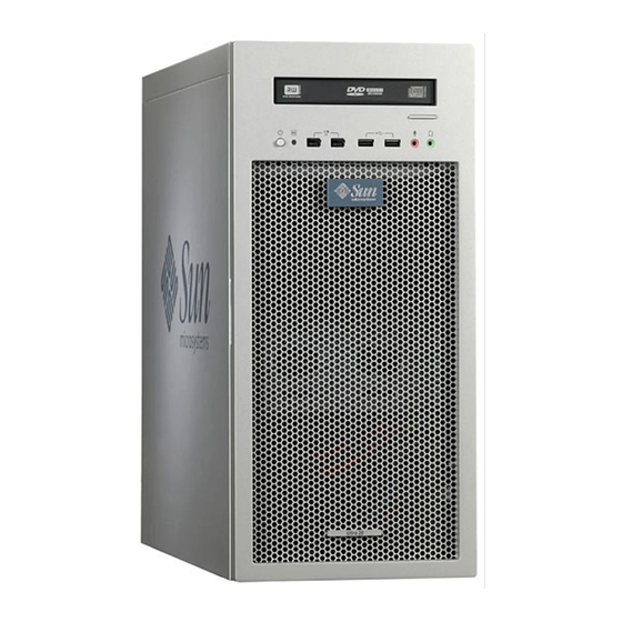
Front Panel illustrates the front panel of the Sun Ultra 20 M2 Workstation. FIGURE 1-1 TABLE 1-1 lists the components called out in the figure. Front Panel Components FIGURE 1-1 Front Panel Components TABLE 1-1 Label Button/LED/Port Label Button/LED/port Power button Two USB 2.0 ports... -
Page 19: Back Panel
Back Panel depicts the back panel of the Sun Ultra 20 M2 Workstation. lists FIGURE 1-2 TABLE 1-2 the components called out in the figure. Back Panel Components FIGURE 1-2 Back Panel Components TABLE 1-2 Label Connector/Slot Label Connector/Slot Power connector Four USB 2.0 connectors... -
Page 20: Internal Components And Cables
PCI Express slots (3) numbered System serial number PCI-E slot 0 (top) to PCI-E slot 2 PCI slots (3) numbered PCI slot 0 Hard disk drive(s) (top) to PCI slot 2 Sun Ultra 20 M2 Workstation Service Manual • January 2007... -
Page 21: Figure
I/O board J12 to motherboard FPB System fan to motherboard SYS_FAN I/O board J8 to motherboard 1394-1 and 1394-2 Power supply P4 to storage backplane J3 CPU fan to motherboard CPU_FAN Chapter 1 Sun Ultra 20 M2 Workstation Hardware Features... - Page 22 Sun Ultra 20 M2 Workstation Service Manual • January 2007...
-
Page 23: Unpacking, Cabling, And Powering The Sun Ultra 20 M2 Workstation
Unpacking, Cabling, and Powering the Sun Ultra 20 M2 Workstation This chapter describes how to connect cables and power the Sun Ultra 20 M2 Workstation on and off. The chapter includes the following sections. Section 2.1, “Planning the Installation Process” on page 2-2 ■... -
Page 24: Planning The Installation Process
Planning the Installation Process Use the following flowchart to assist you with installing the Sun Ultra 20 M2 Workstation. START Unpack the workstation and familiarize yourself with the Chapter workstation features. To install DIMMs, a graphic Install Install optional accelerator, PCI/PCI-E... -
Page 25: Checking Package Contents
* Depending on the system configuration ordered, some systems might not include documentation or the Tools and Drivers CD. A country kit is optional, ships in a separate package, and includes a power cable, keyboard, and mouse. Chapter 2 Unpacking, Cabling, and Powering the Sun Ultra 20 M2 Workstation... -
Page 26: Connecting External Devices To The Workstation
3. Connect the mouse to the USB connector on the underside of the keyboard or to a USB connector on the front or back panel. 4. Connect the Ethernet cable to either Ethernet connector on the Sun Ultra 20 M2 Workstation, and connect the other end of the cable to an Ethernet RJ-45 jack. -
Page 27: Figure 2-3 Connecting The Monitor To The System
Your graphics card might require a DVI cable to connect to your monitor. Connecting the Monitor to the System FIGURE 2-3 6. Connect any additional external devices to the workstation’s other connectors. Chapter 2 Unpacking, Cabling, and Powering the Sun Ultra 20 M2 Workstation... -
Page 28: Powering On The Workstation
This option shuts down the power to the workstation but does not initiate an orderly shutdown of the operating system. This option might result in data loss. Sun Ultra 20 M2 Workstation Service Manual • January 2007... - Page 29 If the proceeding options do not power off the workstation, turn the power switch on the back panel to the Off ( 0 ) position. After powering off the workstation, wait at least four seconds before powering on the workstation again. Chapter 2 Unpacking, Cabling, and Powering the Sun Ultra 20 M2 Workstation...
- Page 30 Sun Ultra 20 M2 Workstation Service Manual • January 2007...
-
Page 31: Troubleshooting
C H A P T E R Troubleshooting This chapter describes visual inspection and troubleshooting procedures, and provides contact information if you require technical assistance. The following sections are included in this chapter: Section 3.1, “Troubleshooting Overview” on page 3-1 ■... -
Page 32: Visual Inspection
Section 5.2, “Opening the Workstation” on page 5-2. Caution – Some components, such as the heatsink, can become extremely hot during system operations. Allow these components to cool before handling them. Sun Ultra 20 M2 Workstation Service Manual • January 2007... -
Page 33: Troubleshooting Procedures
5. Verify that the components are fully seated in their sockets or connectors and that the sockets are clean. 6. Verify that all cables inside the system are firmly attached to their appropriate connectors. 7. Replace the left side access panel. 8. - Page 34 The network status • Check the cabling and network equipment to make sure that all indicator does not cables are correctly seated. light up. • Reinstall the network drivers. Sun Ultra 20 M2 Workstation Service Manual • January 2007...
- Page 35 Troubleshooting Procedures (Continued) TABLE 3-1 Problem Possible solution Newly installed • Make sure that the memory is properly seated on the DIMM memory is not sockets. detected. • Move the memory to the other DIMM socket to determine whether the socket is defective. •...
-
Page 36: Table 3-1 Troubleshooting Procedures
1. Press the Power button to power off the system. 2. Wait 20 to 30 seconds and power on the system. Section 2.5, “Powering Off the Workstation” on page 2-6 more detailed information. Sun Ultra 20 M2 Workstation Service Manual • January 2007... - Page 37 Troubleshooting Procedures (Continued) TABLE 3-1 Problem Possible solution There is no video Check the following: display on the Try to access your system from a different workstation on the monitor screen. network. 1. From a terminal window, type: ping hostname 2.
-
Page 38: Obtaining Technical Assistance
TABLE 3-2 Sun Web Sites and Telephone Numbers TABLE 3-2 Workstation Documents and Support Resources URL or Telephone Number PDF files for all the current Sun Ultra 20 M2 http://www.sun.com/documentation/ Workstation documents. Solaris OS and other software documents. This http://docs.sun.com/documentation/ web site has full search capabilities. -
Page 39: Running Diagnostics
Sun Ultra 20 M2 Workstation Tools and Drivers CD. If you encounter a hardware-related error message (such as a memory error or hard disk error) on your Sun Ultra 20 M2 Workstation, run one of the following tests: Advanced Diagnostics Test: Specific hardware component tests ■... -
Page 40: Understanding The Diagnostic Partition
Your workstation must be running a Sun-supported Linux or Solaris™ OS. Refer ■ to the Sun Ultra 20 M2 Workstation Operating System Installation Guide for a list of supported operating systems. You must access and execute Pc-Check from the Sun Ultra 20 M2 Workstation ■... -
Page 41: System Information Menu
IDE Bus Information Shows the master/slave devices on the primary and secondary IDE controllers. PCMCIA/CardBus Info Not relevant to the Sun Ultra 20 M2 Workstation. Interrupt Vectors Details and lists device interrupt vector information. IRQ Information Shows hardware interrupt assignments. -
Page 42: Advanced Diagnostics
Motherboard Details information about the motherboard and includes a Motherboard Tests menu to test the motherboard on the system. Diskettes Not relevant to Sun Ultra 20 M2 Workstation. Sun Ultra 20 M2 Workstation Service Manual • January 2007... - Page 43 Details information about devices attached to the IDE controllers on the system other than a DVD or hard disks (for example, zip drives). Serial Ports Not applicable for the Sun Ultra 20 M2 Workstation. Parallel Ports Not applicable for the Sun Ultra 20 M2 Workstation. Modems Not applicable for the Sun Ultra 20 M2 Workstation.
-
Page 44: Hard Disk Drive Testing
The Device Test options include the Mechanics Stress Test and the Internal Cache Test. These tests are relevant to testing nonmedia-related devices associated with the HDD hardware, such as the head and internal cache. Sun Ultra 20 M2 Workstation Service Manual • January 2007... -
Page 45: Table 4-3 Parameters For The Hdd Tests
As well as choosing any of these tests, you can also define several parameters of the test. You can change the parameters within the Test Settings option. gives TABLE 4-3 the options within Test Settings. Parameters for the HDD Tests TABLE 4-3 Option Description... -
Page 46: Immediate Burn-In Testing
Individual Passes, Overall Passes, or Overall Time Duration 01:00 Type any number to choose the time duration of the test Script File quick.tst, quick.tst, noinput.tst, or noiniput.tst, or full.tst full.tst Sun Ultra 20 M2 Workstation Service Manual • January 2007... - Page 47 Continuous Burn-in Testing Options (Continued) TABLE 4-4 Default Using quick.tst, noinput.tst, or full.tst Option Default – General Script All Possible Choices Report File None None User-defined Journal File None User-defined D:\noinput.jrl, D:\ quick.jrl, or D:\ full.jrl Journal Options Failed Tests All Tests, Absent Devices, and Failed Tests, All Tests, Absent Test Summary...
-
Page 48: Deferred Burn-In Testing
TABLE 4-4 Select Tests ■ Opens a listing of all of the possible types of tests available for you to run for the currently loaded test script. 4-10 Sun Ultra 20 M2 Workstation Service Manual • January 2007... -
Page 49: Create Diagnostic Partition
Create Diagnostic Partition The diagnostic partition is preinstalled on the Sun Ultra 20 M2 Workstation. You need to reinstall the diagnostic partition only if you reformatted your hard drive. Using the Erase Primary Boot Hard Disk utility on the Tools and Drivers CD preserves the diagnostic partition (see the Sun Ultra 20 M2 Workstation Operating System Installation Guide). -
Page 50: Creating A Log File On The Diagnostic Partition
4. From the main menu, choose Create Diagnostic Partition. If the first bootable disk is clear of partitions, the Sun Microsystems Partitioning ■ Utility window appears. It states: “Your primary hard disk is not partitioned. Would you like to partition it now?”... -
Page 51: Accessing The Diagnostic Partition Under Red Hat Linux
9. Select Exit to DOS and press the Enter key. 10. At the DOS prompt, type the following: C:> d: 11. Type the following to list the contents of the diagnostic partition. D:> dir The noinput.jrl log displays. 4.7.3 Accessing the Diagnostic Partition Under Red Hat Linux Perform this procedure to access the diagnostic partition when you are running a Red Hat Linux OS. -
Page 52: Accessing The Diagnostic Partition Under The Solaris 10 Operating System
Solaris 10 Operating System. 1. Remove the Tools and Drivers CD from the DVD drive tray. 2. Reboot the machine and start the Solaris 10 Operating System. 3. Log in as superuser. 4-14 Sun Ultra 20 M2 Workstation Service Manual • January 2007... - Page 53 4. Type the following command to determine if your diagnostic partition is configured to be mounted: # ls /diagpart If this command does not list the log files created by the hardware diagnostics ■ software, then the OS is not configured to mount the diagnostic partition. Continue to Step If this command lists the log files created by the hardware diagnostics software,...
-
Page 54: Accessing The Diagnostic Partition Under Windows Xp
USB diskette drive to the Sun Ultra 20 M2 Workstation and complete the following procedure. 1. Connect the USB diskette drive to any USB port on the Sun Ultra 20 M2 Workstation. 2. Insert the Tools and Drivers CD into the DVD drive tray. -
Page 55: Show Results Summary
Show Results Summary The summary lists the tests run and shows the results. Pass, Fail, or N/A (not applicable) displays for each option. lists all possible options that are available with the Tools and Drivers CD. TABLE 4-5 Some options might not appear when the Show Results Summary displays if they are not applicable to your workstation’s configuration. -
Page 56: Print Results Report
Controller Tests and Functional Tests. Hardware ID The compare test is used to determine the machine ID for the system. This test is not available for the Sun Ultra 20 M2 Workstation. Print Results Report The Print Results Report option enables you to print the results of the diagnosis of your system. -
Page 57: Maintaining The Workstation
Maintaining the Workstation This chapter provides instructions on how to add, replace, and configure the components in the Sun Ultra 20 M2 Workstation after it is set up. The following sections are included in this chapter: Section 5.1, “Electrostatic Discharge (ESD) Precautions” on page 5-2 ■... -
Page 58: Electrostatic Discharge (Esd) Precautions
This section describes how to remove the left side access panel and the front bezel. 5.2.1 Tools and Supplies Needed Phillips screwdriver ■ Flat-head screwdriver ■ Antistatic wrist strap (shipped with every CRU) ■ Sun Ultra 20 M2 Workstation Service Manual • January 2007... -
Page 59: Powering Off The System And Removing The Left Side Access Panel
5.2.2 Powering Off the System and Removing the Left Side Access Panel Before you remove, replace, or install any components, perform the following steps. 1. Power off the system and all of the peripherals connected to it. 2. Turn the power switch on the back of the chassis to the Off position ( 0 ). Caution –... -
Page 60: Removing The Front Bezel
Caution – Be very careful when pulling the bezel away from the chassis. The bezel tabs and the chassis hooks might break if you apply too much force or attempt to swing the bezel open. Removing the Front Bezel FIGURE 5-2 Sun Ultra 20 M2 Workstation Service Manual • January 2007... -
Page 61: Closing The Workstation
3. Gently move the left-front side of the bezel slightly to the left, then forward to disengage the three chassis hooks on the right side (see FIGURE 5-2 4. Remove the bezel and set it aside. Closing the Workstation This section describes how to install the left side access panel and the front bezel. 5.3.1 Postinstallation Instructions Perform the following steps after installing a workstation component. -
Page 62: Installing The Left Side Access Panel
2. Reinstall any PCI cards, PCI-E cards, or peripherals that you removed. 3. Reinstall the front bezel. 4. Position the access panel so the lip on the inside bottom of the panel fits over the bottom chassis rail. Sun Ultra 20 M2 Workstation Service Manual • January 2007... -
Page 63: Figure 5-4 Installing The Left Side Access Panel
5. Pressing gently against the top of the access panel, slide the panel toward the front of the chassis. See FIGURE 5-4 The access panel lies flat against the chassis, with no gaps between the two. 6. Tighten the two captive thumbscrews located on the rear lip of the panel. The access panel is installed flat against the chassis with the thumbscrews tightened. -
Page 64: Removing Or Adding A Hard Disk Drive
Hard drive assembly–Installed HDDs, the HDD cage, and the storage backplane. ■ 5.4.1 Removing a Hard Disk Drive Note – The Sun Ultra 20 M2 Workstation accommodates up to two HDDs. If you are not removing an existing HDD, proceed to Section 5.4.2, “Installing a Hard Disk Drive” on page 5-10. -
Page 65: Figure 5-5 Removing A Hard Disk Drive
4. Push the plastic latch in the direction of the engraved arrow (away from the metal locking handle) until the HDD handle pops out (see FIGURE 5-5 Removing a Hard Disk Drive FIGURE 5-5 5. Grasp the HDD handle and pull straight up to remove the HDD from the system. 6. -
Page 66: Installing A Hard Disk Drive
2. Gently lay the system on its right side on a stable, nonslip surface. 3. Remove the new HDD from its antistatic packaging. Caution – Handle the HDD with care. Dropping or jarring the HDD can cause damage. 5-10 Sun Ultra 20 M2 Workstation Service Manual • January 2007... -
Page 67: Figure 5-6 Installing A Hard Disk Drive
4. Push the plastic latch in the direction of the engraved arrow (away from the metal handle) until the HDD handle pops out. Installing a Hard Disk Drive FIGURE 5-6 5. Locate the HDD assembly and HDD cage guides. You must install a boot drive in HDD1, the top slot. Install a secondary HDD in HDD2, the bottom slot. -
Page 68: Installing Sas Card, Cables, And Hard Drives
PCI-E2 is the preferred slot. This x8 slot should be used because it is best to reserve PCI-E0 (x16) for the graphics card, but the card will work in either slot. for PCI card locations. FIGURE 5-7 5-12 Sun Ultra 20 M2 Workstation Service Manual • January 2007... -
Page 69: Figure 5-7 Installing A Sas Card
5. Using a No. 2 Phillips screwdriver, remove the chassis filler panel from the PCI card slot. . Save the screw for the next step. FIGURE 5-19 6. Insert the SAS card into the PCIe card slot and secure the card with a screw. FIGURE 5-7 7. - Page 70 10. Install a new operating system for the new SAS configuration. Refer to the Sun Ultra 20 M2 Workstation Operating System Installation Guide at: http://www.sun.com/products-n-solutions/hardware/docs/ Workstation_Products/Workstations/ultra_20m2/index.html Note – This step is necessary only if your SAS drive does not contain a preinstalled operating system.
-
Page 71: Replacing The Storage Backplane
Replacing the Storage Backplane This section describes how to remove and install the storage backplane. For a definition of terms used in this section, see Section 5.4, “Removing or Adding a Hard Disk Drive” on page 5-8. 5.6.1 Removing the Storage Backplane Perform this procedure to remove the storage backplane. -
Page 72: Figure 5-9 Removing The Storage Backplane
Note – Do not attempt to remove the HDD cage. 7. Remove the storage backplane and set it aside. Section 5.6.2, “Installing the Storage Backplane” on page 5-17 8. Proceed to to install the new storage backplane. 5-16 Sun Ultra 20 M2 Workstation Service Manual • January 2007... -
Page 73: Installing The Storage Backplane
5.6.2 Installing the Storage Backplane Perform this procedure to install a storage backplane. 1. Ensure that the power switch on the back panel is in the Off position ( 0 ), and that the system is lying on its side with the left side access panel removed. 2. - Page 74 Be sure that the storage interface cables are seated in the storage backplane ■ connectors. Section 5.3.1, “Postinstallation 8. To close the system, perform the steps in Instructions” on page 5-5. 5-18 Sun Ultra 20 M2 Workstation Service Manual • January 2007...
-
Page 75: Replacing The Dvd Drive
Replacing the DVD Drive This section describes the procedures to remove and replace the DVD drive. 5.7.1 Removing the DVD Drive Perform this procedure to remove the DVD drive. 1. Remove any media in the DVD drive. 2. Follow the instructions in Section 5.2.2, “Powering Off the System and Removing the Left Side Access Panel”... -
Page 76: Installing The Dvd Drive
Installing the DVD Drive FIGURE 5-12 4. To lock the drive in the drive bay, rotate the drive retaining lever downward. 5. Verify that the drive is captured by the retaining hooks. 5-20 Sun Ultra 20 M2 Workstation Service Manual • January 2007... -
Page 77: Figure 5-13 Location Of Power And Ide Cables
6. Connect the IDE, power, and jumper cables to the back of the DVD drive (see FIGURE 5-13 Refer to the cabling diagram in the service label on the side of the chassis for information on correct cable routing. Location of Power and IDE Cables FIGURE 5-13 7. -
Page 78: Removing Or Installing Dimms
2. Gently lay the system on its right side on a stable, nonslip surface. 3. Identify the location from which you will remove a DIMM (see FIGURE 5-14 DIMM Locations FIGURE 5-14 5-22 Sun Ultra 20 M2 Workstation Service Manual • January 2007... -
Page 79: Installing Dimms
4. Place your forefingers on the top of the DIMM. 5. Remove the DIMM by pressing down on the ejector bars at both ends of the DIMM socket ( FIGURE 5-15 Removing a DIMM FIGURE 5-15 6. Set the DIMM aside on an antistatic surface. 7. -
Page 80: Reconfiguring The System Memory
Reconfiguring the System Memory The system automatically detects the amount of memory installed. Run the BIOS setup to view the new value for total system memory, and make a note of it. 5-24 Sun Ultra 20 M2 Workstation Service Manual • January 2007... -
Page 81: Removing And Installing A Pci-E Card
Removing and Installing a PCI-E Card This section describes how to remove and install a PCI Express (PCI-E) card. To remove and replace PCI cards, see Section 5.10, “Removing and Installing PCI Cards” on page 5-29. 5.9.1 Removing a PCI-E Card Perform this procedure to remove a PCI-E card. -
Page 82: Figure 5-17 Removing A Pci-E Graphics Card
If you are not replacing the graphics card, replace the slot filler panel, then close ■ the system by performing the steps in Section 5.3.1, “Postinstallation Instructions” on page 5-5. 5-26 Sun Ultra 20 M2 Workstation Service Manual • January 2007... -
Page 83: Installing A Pci-E Card
5.9.2 Installing a PCI-E Card Note – See Section 1.3, “Internal Components and Cables” on page 1-4 for PCI-E slot locations and to Section A.3, “PCI-E and PCI Expansion Slots” on page A-4, for slot specifications. Follow this procedure to install a card into a PCI-E slot. 1. -
Page 84: Figure 5-18 Installing A Pci-E Graphics Card
8. If you are installing an NVIDIA FX3500 graphics card, connect the graphics power cable to the connector on the card. This might require moving the cable out of its cable tie. Installing a PCI-E Graphics Card FIGURE 5-18 5-28 Sun Ultra 20 M2 Workstation Service Manual • January 2007... -
Page 85: Removing And Installing Pci Cards
9. Fasten the retaining screw into place. Torque the screws to 8- to 9-inch pounds. 10. Close the system by performing the steps in Section 5.3.1, “Postinstallation Instructions” on page 5-5. Note – The onboard ATI graphics controller automatically stops working when you install a graphics card into the PCI-E x16 slot (PCI-E slot 0). -
Page 86: Figure 5-19 Removing A Pci Card
Section 5.3.1, “Postinstallation Instructions” on page 5-5. If you are replacing the card, follow the instructions in Section 5.10.2, “Installing a ■ PCI Card” on page 5-31. 5-30 Sun Ultra 20 M2 Workstation Service Manual • January 2007... -
Page 87: Installing A Pci Card
5.10.2 Installing a PCI Card Note the following if you are installing 33 Mhz PCI cards: Slot 0 can accept only a 32-bit full-length card (64-bit cards are too long). ■ Slot 1 and Slot 2 can accept 32- or 64-bit full-length cards. ■... -
Page 88: Figure 5-20 Installing A Pci Card
8. Fasten the retaining screw into place. Torque the screws to 8- to 9-inch pounds. 9. Close the system by performing the steps in Section 5.3.1, “Postinstallation Instructions” on page 5-5. 5-32 Sun Ultra 20 M2 Workstation Service Manual • January 2007... -
Page 89: Replacing The System Battery
5.11 Replacing the System Battery The battery specifications for the Sun Ultra 20 M2 Workstation are shown in TABLE 5-1 Battery Specifications TABLE 5-1 Specification Value Voltage 3 VDC Type CR 2032 Perform this procedure to remove and replace the system battery. -
Page 90: Figure 5-21 Removing The System Battery
4. Lift the battery to remove it (see FIGURE 5-21 Removing the System Battery FIGURE 5-21 5-34 Sun Ultra 20 M2 Workstation Service Manual • January 2007... -
Page 91: Figure 5-22 Installing A System Battery
5. Insert a new battery with the positive sign (+) facing up (see FIGURE 5-22 Tilt the battery into the battery connector, angling the battery under the battery latch. Slide the battery until it clicks into place. Installing a System Battery FIGURE 5-22 6. -
Page 92: Replacing The System Fan
(see FIGURE 5-23 Removing the System Fan FIGURE 5-23 7. Pull the fan away from the chassis. 8. Remove the new fan from its package. 5-36 Sun Ultra 20 M2 Workstation Service Manual • January 2007... -
Page 93: Figure 5-24 Installing The System Fan
9. Locate the four corner holes in the chassis grill where the fan tabs will be installed. 10. Gently press the fan against the chassis, with the four hooks on the back of the fan bracket in the corner holes on the chassis grill. 11. -
Page 94: Replacing The Power Supply
3. Gently lay the system on its right side on a stable, nonslip surface. 4. Locate the power supply (see FIGURE 5-25 Location of the Power Supply FIGURE 5-25 5-38 Sun Ultra 20 M2 Workstation Service Manual • January 2007... -
Page 95: Locations Of Power Supply Connections On The Motherboard
5. Unfasten the connectors from the motherboard and release the cable management straps (see FIGURE 5-26 6. Unfasten the power connectors attached to the motherboard, DVD drive, and storage backplane (see FIGURE 5-26 TABLE 5-2 Locations of Power Supply Connections on the Motherboard FIGURE 5-26 Power Supply Cable Connections TABLE 5-2... -
Page 96: Figure 5-27 Removing The Power Supply From The Chassis
FIGURE 5-27 Removing the Power Supply From the Chassis FIGURE 5-27 9. Install the new power supply as shown as Section 5.13.2, “Installing the Power Supply” on page 5-41. 5-40 Sun Ultra 20 M2 Workstation Service Manual • January 2007... -
Page 97: Installing The Power Supply
5.13.2 Installing the Power Supply Perform this procedure to install the power supply. 1. Remove the new power supply from its package. 2. Locate where the power supply is to be installed, then place the power supply inside the chassis (see FIGURE 5-28 a. -
Page 98: Replacing The I/O Board Assembly
Section 5.2.3, “Removing the Front Bezel” on page 5-4). 4. Locate the back of the I/O board assembly within the workstation. 5. Disconnect all cables on the back of the I/O board. 5-42 Sun Ultra 20 M2 Workstation Service Manual • January 2007... -
Page 99: Figure 5-29 Removing The I/O Board Assembly
6. Loosen the captive screw securing the I/O board to the metal frame (see FIGURE 5-29 Removing the I/O Board Assembly FIGURE 5-29 7. Push the I/O board out the front of the chassis. 8. Install the new I/O board assembly as shown in Section 5.14.2, “Installing the I/O Board Assembly”... -
Page 100: Installing The I/O Board Assembly
I/O board connections. 6. Replace the front bezel. 7. Close the system by performing the steps in Section 5.3.1, “Postinstallation Instructions” on page 5-5. 5-44 Sun Ultra 20 M2 Workstation Service Manual • January 2007... -
Page 101: Replacing System Cables
5.15 Replacing System Cables The following system cables have a connector at each end and can be removed or installed by the customer. All other cables are permanently attached to a system component at one end and must be removed or replaced along with the component. Section 1.3, “Internal Components and Cables”... -
Page 102: Replacing The Heatsink And Cpu
Caution – The heatsink can become extremely hot. Allow a few minutes for the heatsink to cool before attempting this procedure. 3. Disconnect the CPU fan cable from its connector on the motherboard. 5-46 Sun Ultra 20 M2 Workstation Service Manual • January 2007... -
Page 103: Figure 5-31 Unlatching The Heatsink/Fan Assembly
4. Pull up the lever on the right side of the heatsink/fan assembly to loosen the metal latch from the hook on the retaining bracket (see FIGURE 5-31 Unlatching the Heatsink/Fan Assembly FIGURE 5-31 5. Push down the metal latch on the left side of the assembly to loosen the latch from the hook on the retaining bracket (see FIGURE 5-31 6. -
Page 104: Figure 5-32 Removing The Heatsink/Fan Assembly From The Motherboard
FIGURE 5-32 Removing the Heatsink/Fan Assembly From the Motherboard FIGURE 5-32 8. Place the heatsink upside down on a flat surface to prevent the thermal grease from contaminating other components. 5-48 Sun Ultra 20 M2 Workstation Service Manual • January 2007... -
Page 105: Installing A Heatsink And Cpu
9. Depress, and then pull up the CPU socket retainer lever up to the fully open position (see FIGURE 5-33 Removing the CPU From the Workstation FIGURE 5-33 10. Lift the CPU out of the socket, leaving the retainer lever in the open position. 11. -
Page 106: Figure 5-34 Installing The Cpu
Using the wrapper of the alcohol wipe or a finger inserted into a clean plastic bag, spread out the thermal grease to a thin, uniform thickness over the CPU. 5-50 Sun Ultra 20 M2 Workstation Service Manual • January 2007... -
Page 107: Figure 5-35 Installing The Heatsink/Fan Assembly
Caution – Do not use an unprotected finger to spread the thermal grease. The oil on your finger will degrade the performance of the thermal grease. 7. Inspect the heatsink/fan assembly for dust and lint. Clean if necessary. 8. Carefully position the heatsink/fan assembly on the CPU, aligning it with the mounting hooks to reduce movement after it makes initial contact with the layer of thermal grease. -
Page 108: Figure 5-36 Securing The Heatsink/Fan Assembly Latches
11. Connect the CPU fan cable to the connector on the motherboard. 12. Close the system by performing the steps in Section 5.3.1, “Postinstallation Instructions” on page 5-5. 5-52 Sun Ultra 20 M2 Workstation Service Manual • January 2007... -
Page 109: Replacing The Motherboard
5.17 Replacing the Motherboard The following sections describe how to remove and install the Sun Ultra 20 M2 Workstation system motherboard. Note – The motherboard is not a CRU and should only be replaced by trained field service technicians. 5.17.1 Removing the Motherboard Perform this procedure to remove the motherboard. -
Page 110: Figure 5-37 Removing The Nine Motherboard Screws
6. Remove the nine Phillips screws that fasten the motherboard to the chassis (see FIGURE 5-37 Removing the Nine Motherboard Screws FIGURE 5-37 Note – Do not remove the four screws that secure the CPU heatsink/fan assembly mounting to the motherboard. 5-54 Sun Ultra 20 M2 Workstation Service Manual • January 2007... -
Page 111: Figure 5-38 Removing The Motherboard From The Chassis
7. Pull the motherboard away from the chassis (see FIGURE 5-38 Removing the Motherboard From the Chassis FIGURE 5-38 Refer to the following sections to remove and replace the CPU and memory: Section 5.16, “Replacing the Heatsink and CPU” on page 5-46 ■... -
Page 112: Installing The Motherboard
Section 5.10.2, “Installing a PCI Card” on page 5-31. ■ 5. Reconnect all internal system cables. Section 5.15, “Replacing System Cables” on page 5-45. 6. Verify that all system components are securely installed or connected. 5-56 Sun Ultra 20 M2 Workstation Service Manual • January 2007... -
Page 113: Figure 5-39 Installing The Motherboard
7. Close the system by performing the steps in Section 5.3.1, “Postinstallation Instructions” on page 5-5. Installing the Motherboard FIGURE 5-39 Chapter 5 Maintaining the Workstation 5-57... -
Page 114: Updating The Bios
2. Download the latest Sun Ultra 20 M2 Workstation Tools and Drivers CD ISO image from the Sun web site. http://www.sun.com/downloads Caution – Ensure that you download the ISO image for the Sun Ultra 20 M2 Workstation. 3. Burn the image to a CD. -
Page 115: Resetting Previous Bios Settings
3. Make any setting changes you require. In particular, ensure that RAID settings are enabled if required, and set the OS to the appropriate operating system. For more information, see the Sun Ultra 20 M2 Workstation Operating System Installation Guide. 4. Press the F10 key to save changes and exit. - Page 116 5-60 Sun Ultra 20 M2 Workstation Service Manual • January 2007...
-
Page 117: System Specifications
A P P E N D I X System Specifications This appendix lists features and specifications for the Sun Ultra 20 M2 Workstation and includes the following sections: Section A.1, “System Components and Features” on page A-2 ■ Section A.2, “Memory Configurations” on page A-3 ■... -
Page 118: System Components And Features
• Two IEEE 1394 connectors on the front panel • Line-in/line-out jacks on the back panel • Microphone-in jack on the front and back panels • Headphone-out jack on the front panel Sun Ultra 20 M2 Workstation Service Manual • January 2007... -
Page 119: Memory Configurations
Memory Configurations lists the possible memory configurations for the Sun Ultra 20 M2 TABLE A-2 Workstation. The system requires DDR2-667, unbuffered, ECC DIMMs installed in pairs (except the base 512 MB configuration). You can purchase DIMM kits at: http://store.sun.com DIMM slots are numbered from DIMM 0 to DIMM 3. Populate DIMM slots starting farthest from the CPU (that is, starting with slot 3). -
Page 120: Pci-E And Pci Expansion Slots
Accommodates 64-bit PCI cards, but cards (PCI v2.3 32-bit/33 Mhz, 5V) operate in 32-bit mode. Physical Specifications lists the physical specifications for the Sun Ultra 20 M2 Workstation. TABLE A-4 Sun Ultra 20 M2 Workstation Physical Specifications TABLE A-4 Specification... -
Page 121: Power Specifications
435 mm Weight (max with 34 lb 15.4 kg packaging) Power Specifications The maximum continuous power for the Sun Ultra 20 M2 Workstation is 400W. , and list additional power specifications for the TABLE A-5 TABLE A-6 TABLE A-7 system. -
Page 122: Environmental Specifications
Environmental Specifications lists the environmental specifications for the Sun Ultra 20 M2 Workstation. TABLE A-8 Sun Ultra 20 M2 Workstation Environmental Specifications TABLE A-8 Specification State British Metric Humidity Operating 7%–93% RH noncondensing, 7%–93% RH noncondensing, 100.4˚ F max wet bulb 38˚... -
Page 123: Bios Post Codes
A P P E N D I X BIOS POST Codes Typically, the BIOS displays warning or error messages on the video display in the event of hardware or configuration errors. However, if the error is so severe that the BIOS halts immediately or cannot initialize the video, you can read the last executed POST code from the port 80 LED. - Page 124 3. Reset keyboard for Winbond 977 series Super I/O chips. Reserved. Reserved. Reserved. Test F000h segment shadow to see whether it is read/write-able or not. If test fails, keep beeping the speaker. Reserved. Sun Ultra 20 M2 Workstation Service Manual • January 2007...
- Page 125 BIOS Port 80 POST Codes (Continued) TABLE B-1 Post Code Description Auto-detect flash type to load appropriate flash R/W codes into the run -time area in F000 for ESCD & DMI support. Reserved. Use walking 1’s algorithm to check out interface in CMOS circuitry. Also, set real-time clock power status, and then check for override.
- Page 126 Reserved. Reserved. Reset keyboard if Early_Reset_KB is defined. For example, Winbond 977 series Super I/O chips. See also POST 63h. Reserved. Test DMA Channel 0. Reserved. Test DMA Channel 1. Sun Ultra 20 M2 Workstation Service Manual • January 2007...
- Page 127 BIOS Port 80 POST Codes (Continued) TABLE B-1 Post Code Description Reserved. Test DMA page registers. Reserved. Reserved. Test 8254. Reserved. Test 8259 interrupt mask bits for channel 1. Reserved. Test 8259 interrupt mask bits for channel 2. Reserved. Reserved. Test 8259 functionality.
- Page 128 Reserved. Reserved. Reset keyboard if Early_Reset_KB is not defined. Reserved. Initialize PS/2 Mouse. Reserved. Prepare memory size information for function call: INT 15h ax=E820h. Reserved. Turn on L2 cache. Reserved. Sun Ultra 20 M2 Workstation Service Manual • January 2007...
- Page 129 BIOS Port 80 POST Codes (Continued) TABLE B-1 Post Code Description Program chipset registers according to items described in Setup & Auto-configuration table. Reserved. 1. Assign resources to all ISA PnP devices. 2. Auto assign ports to onboard COM ports if the corresponding item in Setup is set to AUTO.
- Page 130 3. Program boot-up speed. 4. Chipset final initialization. 5. Power management final initialization. 6. Clear screen and display summary table. 7. Program K6 write allocation. 8. Program P6 class write combining. Sun Ultra 20 M2 Workstation Service Manual • January 2007...
- Page 131 BIOS Port 80 POST Codes (Continued) TABLE B-1 Post Code Description Update keyboard LED and typematic rate. 1. Build MP table. 2. Build and update ESCD. 3. Set CMOS century to 20h or 19h. 4. Load CMOS time into DOS timer tick. 5.
- Page 132 B-10 Sun Ultra 20 M2 Workstation Service Manual • January 2007...
- Page 133 Index battery, 5-33 bezel access panel removal, 5-6 installing, 5-5 adding removing, 5-4 hard disk drives, 5-10 cables PCI cards, 5-31 locating, 1-5 PCI-E cards, 5-25 replacing, 5-45 connecting external, 2-4 front panel, 1-2 back panel, 1-3 heatsink and CPU battery installing, 5-49 replacing, 5-33...
- Page 134 POST codes installing, 5-49 BIOS, B-1 removing, 5-46 power supply cable routing, 1-5 installing, 5-41 I/O board assembly power specifications, A-5 front panel view, 1-2 removing, 5-38 installing, 5-44 Index-2 Sun Ultra 20 M2 Workstation Service Manual • January 2007...
- Page 135 powering off, 2-6 powering on, 2-6 updating BIOS, 5-58 precautions for installation USB, 1-3, 5-45, A-2 ESD, 5-2 visual inspection replacing external, 3-2 battery, 5-33 internal, 3-2 DIMMs, 5-22 to 5-24 graphics card, 5-25 to 5-29 heatsink and CPU, 5-46 to 5-52 I/O board assembly, 5-42 to 5-44 motherboard, 5-53 to 5-57 PCI-E cards, 5-25 to 5-29...
- Page 136 Index-4 Sun Ultra 20 M2 Workstation Service Manual • January 2007...
Need help?
Do you have a question about the Ultra 20 M2 and is the answer not in the manual?
Questions and answers