3Com Switch 7700 Configuration Manual
Switch
Hide thumbs
Also See for Switch 7700:
- Configuration manual (330 pages) ,
- Installation manual (59 pages) ,
- Datasheet (8 pages)

Subscribe to Our Youtube Channel
Related Manuals for 3Com Switch 7700


Summary of Contents for 3Com Switch 7700
-
Page 1: Configuration Guide
Switch 7700 Configuration Guide Version 3.0 http://www.3com.com/ Published November 2004 Part No.10014298... - Page 2 3Com Corporation reserves the right to revise this documentation and to make changes in content from time to time without obligation on the part of 3Com Corporation to provide notification of such revision or change. 3Com Corporation provides this documentation without warranty, term, or condition of any kind, either implied or expressed, including, but not limited to, the implied warranties, terms or conditions of merchantability, satisfactory quality, and fitness for a particular purpose.
-
Page 3: Table Of Contents
BOUT UIDE Conventions YSTEM CCESS Product Overview Function Features Configuring the Switch 7700 Setting Terminal Parameters Configuring Through Telnet Configuring Through a Dial-up Modem Configuring the User Interface Command Line Interface Command Line View Features and Functions of the Command Line... - Page 4 ETWORK ROTOCOL PERATION Configuring IP Address Subnet and Mask Configuring an IP Address Troubleshooting an IP Address Configuration Configuring Address Resolution Protocol (ARP) Configuring ARP DHCP Relay Configuring DHCP Relay Troubleshooting a DHCP Relay Configuration IP Performance Configuring TCP Attributes Configuring Special IP Packet Transmission to the CPU Configuring L3 Broadcast Forwarding Displaying and Debugging IP Performance...
- Page 5 S/ O PERATION ACL Overview Filtering or Classifying Data Transmitted by the Hardware Filtering or Classifying Data Transmitted by the Software ACL Support on the Switch 7700 Configuring ACLs Configuring the Time Range Selecting the ACL Mode Defining an ACL...
- Page 6 Activating an ACL ACL Configuration Examples Access Control Basic ACL Link ACL Configuring QoS Qos Concepts Configuring QoS QoS Configuration Examples Configuring ACL Control Configuring ACL Control for TELNET Users Configuring ACL Control for SNMP Users STP O PERATION STP Overview Configuring STP Designating Switches and Ports Calculating the STP Algorithm...
- Page 7 Configuring File Management TFTP Managing the MAC Address Table Configuring the MAC Address Table Managing Devices Rebooting the Switch 7700 Designating the APP for the Next Boot Displaying Devices Maintaining and Debugging the System Configuring System Basics Displaying System Information and State...
- Page 8 Configuring RMON Configuring NTP NTP Configuration Examples SSH Terminal Services Configuring the SSH Server Configuring the SSH Client Specifying the Server IP Address Displaying and Debugging SSH SSH Configuration Example...
-
Page 9: About This Guide
BOUT UIDE This guide describes the 3Com ® Switch 7700 and how to configure it in version 3.0 of the software. Conventions Table 1 lists icon conventions that are used throughout this book. Table 1 Notice Icons Icon Notice Type... - Page 10 BOUT UIDE...
-
Page 11: System
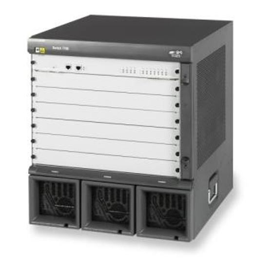
Command Line Interface ■ Product Overview The 3Com Switch 7700 is a large capacity, modularized wire speed Layer 2/Layer 3 Switch 7700. It is designed for IP metropolitan area networks (MAN), large-sized enterprise networks, and campus network users. The Switch 7700 has an integrated chassis structure. The chassis contains a card area, fan area, power supply area, and a power distribution area. -
Page 12: Configuring The Switch 7700
Loading and upgrading software using the File Transfer Protocol (FTP) and Trivial File Transfer Protocol (TFTP) Configuring the On the Switch 7700, you can set up the configuration environment through the Switch 7700 console port. To set up the local configuration environment: 1 Plug the DB-9 or DB-25 female plug of the console cable into the serial port of the PC or the terminal where the switch is to be configured. -
Page 13: Setting Terminal Parameters
Setting Terminal Parameters Figure 1 Setting Up the Local Configuration Environment Through the Console Port RS-232 Serial port Console port Console cable Setting Terminal To set terminal parameters: Parameters 1 Start the PC and select Start > Programs > Accessories > Communications > HyperTerminal. - Page 14 1: S HAPTER YSTEM CCESS Figure 3 Properties Dialog Box 5 Click OK. The Port Settings tab, shown in Figure 4, displays and you can set serial port parameters. Set the following parameters: Baud rate = 9600 ■ Databit = 8 ■...
- Page 15 Setting Terminal Parameters Figure 4 Set Communication Parameters 6 Click OK. The HyperTerminal dialogue box displays, as shown in Figure 5. 7 Select Properties. Figure 5 HyperTerminal Window 8 In the Properties dialog box, select the Settings tab, as shown in Figure 6. 9 Select VT100 in the Emulation dropdown menu.
-
Page 16: Configuring Through Telnet
Before you can telnet to a Switch 7700 and configure it, you must: Telnet 1 Configure the IP address of a VLAN interface for the Switch 7700 through the console port (using the ip address command in VLAN interface view) - Page 17 1 Authenticate the Telnet user through the console port before the user logs in by Telnet. By default, a password is required for authenticating the Telnet user to log in the Switch 7700. If a user logs in by Telnet without a password, the user sees the message: Login password has not been set! 2 Enter system view, return to user view by pressing Ctrl+Z.
- Page 18 2 Add the port (that connects to a terminal) to this VLAN (using the port command in VLAN view) 3 Log in to the Switch 7700 After you telnet to a Switch 7700, you can run the telnet command to log in and configure another Switch 7700. Figure 9 Provide Telnet Client Service...
-
Page 19: Configuring Through A Dial-Up Modem
[SW7700-ui-aux0] modem 2 To set up the remote configuration environment, connect the modems to a PC (or a terminal) serial port and to the Switch 7700 console port, as shown in Set Up Remote Configuration Environment. Figure 10 Set Up Remote Configuration Environment... -
Page 20: Configuring The User Interface
4 Enter the preset login password on the remote terminal emulator and wait for the prompt. <SW7700> 5 Use the appropriate commands to configure the Switch 7700 or view its operational state. Enter to get immediate help. For details on a specific command, refer to the appropriate chapter in this guide. - Page 21 VTY user interface is used to telnet the Switch 7700. ■ For the Switch 7700, the AUX port and Console port are the same port. There is only the type of AUX user interface. The user interface is numbered by absolute number or relative number.
- Page 22 Enabling and Disabling Terminal Service After the terminal service is disabled on a user interface, you cannot log in to the Switch 7700 through the user interface. However, if a user logged in through the user interface before disabling the terminal service, the user can continue operation.
- Page 23 Setting Terminal Parameters By default, terminal service is enabled on all the user interfaces. Note the following points: For the sake of security, the undo shell command can only be used on the user ■ interfaces other than the AUX user interface. You cannot use this command on the user interface through which you log in.
- Page 24 Remove the local authentication password undo set authentication password Configure for password authentication when a user logs in through a VTY 0 user interface and set the password to 3Com: [SW7700] user-interface vty 0 [SW7700-ui-vty0] authentication-mode password [SW7700-ui-vty0] set authentication password simple 3Com 2 Configure the local or remote authentication username and password.
- Page 25 Setting Terminal Parameters Perform username and password authentication when a user logs in through the VTY 0 user interface and set the username and password to zbr and 3Com respectively: [SW7700-ui-vty0] authentication-mode scheme [SW7700-ui-vty0] quit [SW7700] local-user zbr [SW7700-luser-zbr] service-type telnet [SW7700-luser-zbr] password simple 3Com 3 Set the Switch 7700 to allow user access without authentication.
- Page 26 1: S HAPTER YSTEM CCESS When a user logs in to the switch, the command level that the user can access depends on two points. One is the command level that the user can access, the other is the set command level of the user interface. If the two levels are different, the former is taken.
- Page 27 Setting Terminal Parameters Perform the following configuration in user view. Table 15 Configure to Send Messages Between User Interfaces Operation Command Configure to send messages between send { all | number | type number } different user interfaces. The auto-execute Command is used to run a command automatically after you log in.
-
Page 28: Command Line Interface
Local configuration through the console port. ■ Local or remote configuration through Telnet. ■ Remote configuration through a dial-up Modem to log in to the Switch 7700. ■ Hierarchy command protection to prevent unauthorized users from accessing ■ the switch. - Page 29 Otherwise, the original user level remains unchanged. Command views are implemented according to requirements that are related to one another. For example, after logging in to the Switch 7700, you enter user view, in which you can only use some basic functions, such as displaying the operating state and statistics information.
- Page 30 1: S HAPTER YSTEM CCESS Figure 13 Relation Diagram of the Views Ethernet port view User interface viiew VLAN view VLAN interface view OSPF area view RIP view OSPF view Route policy view Basic ACL view System Advanced ACL view User view view Interface-based ACL view...
-
Page 31: Features And Functions Of The Command Line
Command Line Interface Table 18 Function Feature of Command View (continued) Command view Function Prompt Command to enter Local-user view Configure local user Enter local-user [SW7700-user- parameters user1 in System view user1] User interface view Configure user Enter user-interface [SW7700-ui0] interface parameters 0 in System view FTP Client view... - Page 32 1: S HAPTER YSTEM CCESS quit Exit from current command view super Enter the command workspace with specified user priority level telnetEstablish one TELNET connection tracertTrace route function Enter a command with a , separated by a space. If this position is for ■...
- Page 33 Command Line Interface Common Command Line Error Messages All the commands that are entered by users can be correctly executed if they have passed the grammar check. Otherwise, error messages are reported to users. Common error messages are listed in Table 19. Table 19 Common Command Line Error Messages Error messages Causes...
- Page 34 1: S HAPTER YSTEM CCESS Table 21 Editing Functions Function Press Tab after typing the incomplete key word and the system will execute the partial help: If the key word matching the typed one is unique, the system will replace the typed one with the complete key word and display it in a new line.
-
Page 35: Port Configuration
■ Configuring Link Aggregation ■ Ethernet Port The following features are found in the Ethernet ports of the Switch 7700: Overview 10BASE-T/100BASE-TX Gigabit Ethernet ports support MDI/MDI-X ■ auto-sensing, and can be configured to operate in half/full duplex mode or auto-negotiation mode to negotiate the duplex mode and speed with other network devices. - Page 36 2: P HAPTER ONFIGURATION Setting Cable Type for Ethernet Port ■ Setting Flow Control for Ethernet Port ■ Permitting/Forbidding Jumbo Frames on the Ethernet port ■ Setting the Maximum MAC Addresses an Ethernet Port can Learn ■ Setting the Link Type for an Ethernet Port ■...
- Page 37 Setting Cable Type for Ethernet Port The Ethernet port supports the straight-through (MDI) and cross-over (MDIX) network cables. The Switch 7700 only supports auto (auto-sensing). If you set some other type, you will see an error message. By default, the cable type is auto (auto-recognized).
- Page 38 2: P HAPTER ONFIGURATION Setting Flow Control for Ethernet Port If congestion occurs in the local switch after enabling flow control in both the local and the peer switch, then the switch will inform its peer to pause sending packets. Once the peer switch receives this message, it will pause packet sending, and vice versa.
- Page 39 By default, 100% broadcast traffic is allowed to pass through, that is, no broadcast suppression will be performed. Note that in the Switch 7700, you can only use the command at the port on a 20-port 10/100/1000BASE-T Gigabit Ethernet card or a 20-port 1000BASE-X Gigabit Ethernet card.
- Page 40 2: P HAPTER ONFIGURATION A port on a switch can be configured as an access port, a hybrid port, or a trunk port. However, to reconfigure between hybrid and trunk link types, you must first restore the default, or access link type. The default link type is the access link type.
-
Page 41: Setting The Vlan Vpn Feature
Ethernet Port Overview Table 13 Set the Default VLAN ID for the Ethernet Port Operation Command Restore the default VLAN ID of the hybrid port undo port hybrid pvid to the default value Restore the default VLAN ID of the trunk port undo port trunk pvid to the default value A Trunk port and isolate-user-vlan cannot be configured simultaneously. -
Page 42: Example: Configuring The Default Vlan Id Of The Trunk Port
2: P HAPTER ONFIGURATION QoS setting — includes traffic limiting, priority marking, default 802.1p priority, ■ bandwidth assurance, congestion avoidance, traffic redirection, traffic statistics. VLAN setting — includes permitted VLAN types, default VLAN ID. ■ Port setting — includes port link type, port speed, duplex mode. LACP setting ■... -
Page 43: Troubleshooting Vlan Port Configuration
Configuring Link Aggregation The following configurations are used for Switch A, configure Switch B in a similar way: 1 Enter the Ethernet port view of Ethernet1/0/1. [SW7700] interface ethernet1/0/1 2 Set the Ethernet1/0/1 as a trunk port and allows VLAN 2, 6 through 50, and 100 to pass through. -
Page 44: Types Of Link Aggregation
VLAN types, default VLAN ID. The port setting includes port link type. The Switch 7700 supports a maximum of sixty four load-balance groups, with each group containing a maximum of eight 1000M ports or sixteen 100M ports. For the 48-port 10/100Base-T auto-sensing fast Ethernet interface card, a port grouped in first 24 ports cannot be aggregated with the one grouped in the last 24 ports. - Page 45 If the Switch 7700 is connected to a peer device on which the maximum ■ number of ports in a link aggregation is smaller than on the Switch 7700, the Switch 7700 sets to active the number of ports that correspond to the peer’s maximum.
-
Page 46: Load Sharing
Selection criteria of selected ports vary for different types of aggregation groups. Configuring Link The Switch 7700 only supports LACP for ports on the same I/O module. A Aggregation maximum number of 16 ports can be active in a link aggregation. For modules that have fewer than 16 ports, such as the 8-port 1000BASE-X-GE module, only eight ports can be active members of a link aggregation. - Page 47 Configuring Link Aggregation Displaying and Debugging Link Aggregation ■ Enabling or Disabling LACP at a Port You should first enable LACP at the ports before performing dynamic aggregation, so that both parties can agree on adding/deleting the ports into/from a dynamic LACP aggregation group.
- Page 48 2: P HAPTER ONFIGURATION to a static one. In the former case, LACP shall be disabled at the member ports automatically, while in the latter case, LACP shall remain enabled. Adding or Deleting Ethernet Ports to or from an Aggregation Group You can add/delete ports into/from a manual or static LACP aggregation group, but member port adding or deleting for a dynamic LACP aggregation group is implemented by the system.
- Page 49 Configuring Link Aggregation Perform the following configuration in system view. Table 21 Configure System Priority Operation Command Configure system priority lacp system-priority system-priority-value Restore the default system priority undo lacp system-priority By default, system priority is 32768. Configuring Port Priority The LACP compares system IDs first and then port IDs (if system IDs are the same) in determining if the member ports are selected or standby ones for a dynamic LACP aggregation group.
-
Page 50: Example: Link Aggregation Configuration
2: P HAPTER ONFIGURATION Table 23 Display and Debug Link Aggregation (continued) Operation Command Disable/enable debugging LACP state machine [ undo ] debugging lacp state [ interface { interface-type interface-number | interface-name } [ to { interface-type interface-num | interface-name } ] ] { { actor-churn | mux | partner-churn | ptx | rx }* | all } Disable/enable debugging LACP packets... - Page 51 Configuring Link Aggregation [SW7700-Ethernet1/0/1] interface ethernet1/0/2 [SW7700-Ethernet1/0/2] port link-aggregation group 1 [SW7700-Ethernet1/0/2] interface ethernet1/0/3 [SW7700-Ethernet1/0/3] port link-aggregation group 1 3 Configure a dynamic LACP aggregation Enable LACP at Ethernet ports Ethernet1/0/1 to Ethernet1/0/3. ■ [SW7700] interface ethernet1/0/1 [SW7700-Ethernet1/0/1] lacp enable [SW7700-Ethernet1/0/1] interface ethernet1/0/2 [SW7700-Ethernet1/0/2] lacp enable [SW7700-Ethernet1/0/2] interface ethernet1/0/3...
- Page 52 2: P HAPTER ONFIGURATION...
-
Page 53: Vlan Configuration
Port-based VLANs define VLAN members according to switch ports. This is the simplest and most efficient way to create VLANs. The Switch 7700 supports port-based and network layer-based VLANs. The network layer-based VLANs are divided by protocols such as IP and IPX, so they are called protocol-based VLANs. -
Page 54: Common Vlan Configuration Tasks
3: VLAN C HAPTER ONFIGURATION Common VLAN The following sections discuss the common tasks for configuring a VLAN: Configuration Tasks Creating or Deleting a VLAN ■ Specifying the Broadcast Suppression Ratio for a VLAN ■ Setting or Deleting the VLAN Description Character String ■... - Page 55 Configuring VLANs Setting or Deleting the VLAN Description Character String You can use the following command to set or delete the VLAN description character string. The description character strings, such as workgroup_name and department_name, are used to distinguish the different VLANs. Perform the following configuration in VLAN view.
- Page 56 3: VLAN C HAPTER ONFIGURATION status of one or more Ethernet ports is UP, the status of the VLAN interface is UP also, so the VLAN interface is enabled. Displaying and Debugging a VLAN After the configuring a VLAN, execute the display command in any view to display the VLAN configuration, and to verify the effect of the configuration.
-
Page 57: Configuring Port-Based Vlans
Configuring VLANs Configuring Port-Based Adding Ethernet Ports to a VLAN VLANs Use the following command to add Ethernet ports to a VLAN. Perform the following configuration in VLAN view. Table 7 Adding Ethernet Ports to a VLAN Operation Command Add Ethernet ports to a VLAN port { interface_type interface_num | interface_name [ to interface_type interface_num | interface_name ] }&... - Page 58 3: VLAN C HAPTER ONFIGURATION Creating and Deleting a VLAN Protocol Type You can use the following command to create or delete a VLAN protocol type. Perform the following configuration in VLAN view. Table 9 Creating and Deleting a VLAN Protocol Type Operation Command Create a VLAN protocol type...
- Page 59 Configuring VLANs [SW7700-vlan2] vlan 3 4 Add Ethernet1/0/3 and Ethernet1/0/4 to VLAN3. [SW7700-vlan3] port ethernet1/0/3 to ethernet1/0/4 From port G1/0/1, all the traffic with source IP 10.0.0.1 will belong to VLAN 2 and Example: Protocol-Based VLAN any other IP traffic will belong to VLAN 3. If we configure port G1/0/2 in VLAN 2, Configuration the traffic with source IP 10.0.0.1 will be sent from port G1/0/2.
- Page 60 3: VLAN C HAPTER ONFIGURATION 2 Configure VLAN 2 and VLAN 3 as protocol VLANs. Set VLAN 2 as IP 10.0.0.1 protocol and VLAN 3 as IP protocol [SW7700-vlan2]protocol-vlan ? Specify AT(AppleTalk Protocol) configuration information Specify IP(Internet Protocol) configuration information Specify IPX(Internetwork Packet eXchange) configuration information mode...
-
Page 61: Configuring Garp/Gvrp
Configuring GARP/GVRP [SW7700-GigabitEthernet1/0/1]port hybrid protocol-vlan 2 0 [SW7700-GigabitEthernet1/0/1]port hybrid protocol-vlan 3 0 [SW7700-GigabitEthernet1/0/1]display th interface GigabitEthernet1/0/1 port link-type hybrid port hybrid vlan 2 to 3 tagged port hybrid vlan 1 untagged port hybrid protocol-vlan 2 0 port hybrid protocol-vlan 3 0 return 4 Configure port G1/0/3 as VLAN 3 and port G1/0/2 as VLAN 2 [SW7700]vlan 3... - Page 62 3: VLAN C HAPTER ONFIGURATION messages cooperate to ensure the logout and the re-registration of a message. By exchanging messages, all the attribute information to be registered can be propagated to all the switches in the same switching network. The destination MAC addresses of the packets of the GARP participants are specific multicast MAC addresses.
-
Page 63: Configuring Gvrp
GVRP includes both the local static registration information that is configured manually and the dynamic registration information from other switches. GVRP is described in the IEEE 802.1Q standard. The Switch 7700 fully supports GARP compliant with the IEEE standards. - Page 64 3: VLAN C HAPTER ONFIGURATION Enabling or Disabling Port GVRP ■ Setting the GVRP Registration Type ■ When you configure GVRP, you need to enable it globally and for each port participating in GVRP. Similarly, the GVRP registration type can take effect only after you configure port GVRP.
- Page 65 Configuring GARP/GVRP When an Ethernet port registration type is set to forbidden, all the VLANs ■ except VLAN1 are logged out and no other VLANs can be created or registered on this port. Perform the following configurations in Ethernet port view. Table 15 Setting the GVRP Registration Type Operation Command...
- Page 66 3: VLAN C HAPTER ONFIGURATION [SW7700-Ethernet1/0/1] vlan 3 [SW7700-vlan3] vlan 4 3 Enable GVRP globally. [SW7700-vlan4] quit [SW7700] gvrp 4 Enable GVRP on the trunk port. [SW7700] interface Ethernet 1/0/1 [SW7700-Ethernet1/0/1] gvrp Configure Switch B: 1 Set Gigabit Ethernet2/1 as a trunk port and allow all the VLANs to pass through. [SW7700] interface Ethernet 2/0/1 [SW7700-Ethernet2/0/1] port link-type trunk [SW7700-Ethernet2/0/1] port trunk permit vlan all...
-
Page 67: Configuring Ip Address
ETWORK ROTOCOL PERATION This chapter covers the following topics: Configuring IP Address ■ Configuring Address Resolution Protocol (ARP) ■ DHCP Relay ■ IP Performance ■ Configuring IPX ■ Configuring IP IP address is a 32-bit address represented by four octets. IP addresses are divided Address into five classes, A, B, C, D and E. -
Page 68: Subnet And Mask
4: N HAPTER ETWORK ROTOCOL PERATION Configuring an IP Address ■ Troubleshooting an IP Address Configuration ■ Subnet and Mask IP protocol allocates one IP address for each network interface. Multiple IP addresses can only be allocated to a device which has multiple network interfaces. IP addresses on a device with multiple interfaces have no relationship among themselves. - Page 69 Configuring IP Address Perform the following configuration in VLAN interface view. Table 2 Configure IP Address for a VLAN Interface Operation Command Configure IP address for a VLAN interface ip address ip-address net-mask [ sub ] Delete the IP address of a VLAN interface [ undo ] ip address [ ip-address { net-mask | mask-length } [ sub ] ] The network ID of an IP address is identified by the mask.
-
Page 70: Troubleshooting An Ip Address Configuration
4: N HAPTER ETWORK ROTOCOL PERATION [SW7700-vlan-interface1] ip address 129.2.2.1 255.255.255.0 Troubleshooting an IP If the Ethernet Switch cannot ping a certain host on the LAN, proceed as follows: Address Configuration 1 Determine which VLAN includes the port connected to the host. Check whether the VLAN has been configured with the VLAN interface. -
Page 71: Configuring Arp
Configuring Address Resolution Protocol (ARP) Configuring ARP The ARP mapping table can be maintained dynamically or manually. Addresses that are mapped manually are referred to as static ARP. The user can display, add, or delete the entries in the ARP mapping table through manual commands. ARP configuration includes tasks described in the following sections: Manually Adding/Deleting Static ARP Mapping Entries ■... -
Page 72: Dhcp Relay
4: N HAPTER ETWORK ROTOCOL PERATION Displaying and Debugging ARP After the previous configuration, execute command in all views to display display the operation of the ARP configuration, and to verify the effect of the configuration. Execute the debugging command in user view to debug the ARP configuration. -
Page 73: Configuring Dhcp Relay
DHCP Relay Then the server transmits the configuration information to the clients through the DHCP relay, thereby, completing the dynamic configuration of the client. Configuring DHCP is described in the following sections: Configuring DHCP Relay ■ Troubleshooting a DHCP Relay Configuration ■... - Page 74 4: N HAPTER ETWORK ROTOCOL PERATION Configuring the Address Table Entry To check the address of users who have valid and fixed IP addresses in the VLAN (with DHCP enabled), it is necessary to add an entry in the static address table. Perform the following configuration in system view.
- Page 75 DHCP Relay Figure 3 Networking Diagram of Configuring DHCP Relay 1.99.255.36 Server Group 1 VLAN VLAN 2 1.99.255.35 4000 IP Network VLAN 1.88.255.36 3001 Server Group 2 VLAN 3 1.88.255.35 1 Configure the DHCP Server IP addresses into DHCP Server Group 1. [SW7700] dhcp-server 1 ip 1.99.255.36 1.99.255.35 2 Associate DHCP Server Group 1 with VLAN interface 2.
-
Page 76: Troubleshooting A Dhcp Relay Configuration
Discover packet and there is no response packet, it means the DHCP Server has not sent the message to the Switch 7700. In this case, check if the DHCP Server has been configured properly. If the numbers of request and response packets are normal, enable the debugging dhcp-relay in User view and then use the terminal debugging command to output the debugging information to the console. -
Page 77: Configuring Special Ip Packet Transmission To The Cpu
IP Performance finwait timer timeout, the TCP connection will be terminated. Finwait ranges 76 to 3600 seconds and it is 675 seconds by default. The receiving/sending buffer size of connection-oriented Socket is in the range ■ from 1 to 32K bytes and is 4K bytes by default. Perform the following configuration in System view. -
Page 78: Displaying And Debugging Ip Performance
4: N HAPTER ETWORK ROTOCOL PERATION If a broadcast packet reaches the destination network after being forwarded by the switch, the switch will receive the broadcast packet; the switch also belongs to the subnet. The VLAN of the switch isolates the broadcast domain, it will stop forwarding the packet to the network. -
Page 79: Ipx Configuration
IPX Configuration Operations include: <SW7700> terminal debugging <SW7700> debugging tcp packet The TCP packets, received or sent can be checked in real time. Specific packet formats include: TCP output packet: Source IP address:202.38.160.1 Source port:1024 Destination IP Address 202.38.160.1 Destination port: 4296 Sequence number :4185089 Ack number: 0 Flag... -
Page 80: Service Advertising Protocol
4: N HAPTER ETWORK ROTOCOL PERATION next site and if there is any, forwards the packet. The routing information can be configured statically or collected dynamically. This chapter introduces RIP in IPX. For the RIP configurations on an IP network, refer to the routing protocol section in this manual. - Page 81 IPX Configuration Assigning IPX Network Numbers to VLAN Interfaces To enable IPX on a VLAN interface after it is enabled globally, you must assign a network number to the VLAN interface. One VLAN interface can have only one network number. Perform the following configuration in VLAN interface view.
- Page 82 4: N HAPTER ETWORK ROTOCOL PERATION Configuring an IPX Route Limit In IPX, you can configure in the routing table the maximum number of the dynamic routes and equivalent routes to the same destination. These two limit settings are independent. Perform the following configuration in system view.
- Page 83 IPX Configuration Configuring the Update Interval of IPX RIP The switch broadcasts RIP update packets periodically. You can configure the update interval of IPX RIP with the following command. Perform the following configuration in system view. Configuring the Update Interval of IPX RIP Table 22 Operation Command...
- Page 84 4: N HAPTER ETWORK ROTOCOL PERATION Perform the following configuration in VLAN interface view. Table 25 Configuring the IPX Forwarding Delay on the VLAN Interface Operation Command Configure the IPX packet forwarding delay on ipx tick ticks the VLAN interface Restore the default forwarding delay undo ipx tick By default, the forwarding delay on the VLAN interface is one tick.
- Page 85 IPX Configuration Configuring the Update Interval of IPX SAP In a huge network, one IPX SAP broadcast consumes enormous bandwidth resources. By configuring an appropriate SAP update interval, you can reduce the bandwidth waste. Perform the following configuration in system view. Table 28 Configuring the Update Interval of IPX SAP Operation Command...
- Page 86 4: N HAPTER ETWORK ROTOCOL PERATION Respond with the information of the nearest server (the server with the ■ smallest hop count in the service information table on the switch). Respond with the information of one server that is picked out from all the ■...
- Page 87 IPX Configuration The following table shows some common service types and their values: Table 34 Service Types and Their Values Service Type Value Unknown 0000h Print Queue 0003h File Server 0004h Job Server 0005h Print Server 0007h Archive Server 0009h Remote Bridge Server 0024h Advertising Print Server...
- Page 88 4: N HAPTER ETWORK ROTOCOL PERATION on the VLAN interfaces on the switch. This allows the switch to broadcast update only when route or service information changes, thus avoiding broadcast flooding. Perform the following configuration in VLAN interface view. Table 36 Configuring Triggered Update of IPX Operation Command Enable triggered update of IPX...
-
Page 89: Ipx Configuration Example
IPX Configuration Perform the following configuration in VLAN interface view. Table 39 Enabling or Disabling Forward IPX Type 20 Broadcast Packets Operation Command Enable the forwarding of type 20 broadcast ipx netbios-propagation packets Disable the forwarding of type 20 broadcast undo ipx netbios-propagation packets By default, type 20 broadcast packets are not forwarded. - Page 90 4: N HAPTER ETWORK ROTOCOL PERATION The client accesses the file and directory services provided by the server through the IPX network. The node address of the server is 0000-0c91-f61f. Figure 4 illustrates this configuration Figure 4 IPX Network Topology 1 Configure Switch A Enable IPX.
-
Page 91: Troubleshooting Ipx
IPX Configuration SW7700] interface vlan-interface 2 [SW7700-Vlan-interface2] ipx network 3 Set the IPX packet encapsulation format to Ethernet_SNAP on VLAN interface 2. [SW7700-Vlan-interface2] ipx encapsulation snap [SW7700-Vlan-interface2] quit Assign the network number 1001 to VLAN interface 1 to enable IPX on the interface. - Page 92 4: N HAPTER ETWORK ROTOCOL PERATION Use the display ipx interface command to check that SAP is not disabled on the ■ VLAN interface. 4 A type 20 IPX packet cannot be transmitted to other network segments. Do the following: Execute the display ipx interface command;...
- Page 93 IPX Configuration Check that the VLAN interface is UP and SAP is enabled with the display ipx ■ interface command. Check that the hop count of the route to the server is smaller than 16 with the ■ display ipx routing-table command. Adequate memory is available for adding the service entry into the service ■...
- Page 94 4: N HAPTER ETWORK ROTOCOL PERATION The switch receives the GNS packets with the debugging ipx packet sap ■ command. SAP is enabled on the VLAN interface where the GNS requests are received. ■ The VLAN interface is enabled to respond to GNS requests with the display ipx ■...
-
Page 95: Ip Routing Protocol Operation
IP R OUTING ROTOCOL PERATION This chapter covers the following topics: IP Routing Protocol Overview ■ Static Routes ■ ■ OSPF ■ IS-IS ■ ■ IP Routing Policy ■ Route Capacity ■ IP Routing Protocol Routers select an appropriate path through a network for an IP packet according Overview to the destination address of the packet. -
Page 96: Selecting Routes Through The Routing Table
5: IP R HAPTER OUTING ROTOCOL PERATION Figure 1 About Hops Route Segment Networks can have different sizes, so, the segment lengths connected between two different pairs of routers are also different. If a router in a network is regarded as a node and a route segment in the Internet is regarded as a link, message routing in the Internet works in a similar way as the message routing in a conventional network. -
Page 97: Routing Management Policy
15.0.0 10.0.0.2 11.0.0.2 12.0.0.2 10.0.0.2 16.0.0 14.0.0.1 12.0.0.0 12.0.0.3 12.0.0.1 Routing Management The Switch 7700 supports the configuration of a series of dynamic routing Policy protocols such as RIP, OSPF, as well as static routes. The static routes configured by... -
Page 98: Static Routes
As the algorithms of various routing protocols are different, different protocols can generate different routes. This situation creates the problem of how to resolve different routes being generated by different routing protocols. The Switch 7700 supports an operation to import the routes generated by one routing protocol into another routing protocol. -
Page 99: Configuring Static Routes
Static Routes In a relatively simple network, you only need to configure static routes to make the router work normally. The proper configuration and usage of the static route can improve network performance and ensure bandwidth for important applications. The following routes are static routes: Reachable route —... - Page 100 5: IP R HAPTER OUTING ROTOCOL PERATION Configuring a Static Route Perform the following configurations in system view. Table 2 Configuring a Static Route Operation Command Add a static route ip route-static ip-address {mask | mask-length } { interface-name | gateway-address } [ preference value ] [ reject | blackhole ] Delete a static route...
- Page 101 Deleting All Static Routes You can use the undo ip route-static command to delete one static route. The Switch 7700 also provides the delete static-route all command for you to delete all static routes at one time, including the default routes.
-
Page 102: Troubleshooting Static Routes
Using this procedure, all the hosts or switches in Figure 3 can be interconnected in pairs. Troubleshooting Static The Switch 7700 is not configured with any dynamic routing protocols enabled. Routes Both the physical status and the link layer protocol status of the interface are enabled, but the IP packets cannot be forwarded normally. -
Page 103: Rip
Routing Information Protocol (RIP) is a simple, dynamic routing protocol, that is Distance-Vector (D-V) algorithm-based. It uses hop counts to measure the distance to the destination host, which is called routing cost. In RIP, the hop count from a router to its directly connected network is 0. The hop count to a network which can be reached through another router is 1, and so on. -
Page 104: Configuring Rip
5: IP R HAPTER OUTING ROTOCOL PERATION validity of the routes. With these mechanisms, RIP, an interior routing protocol, enables the router to learn the routing information of the entire network. RIP has become one of the most popular standards of transmitting router and host routes. - Page 105 By default, RIP is not enabled. Enabling the RIP Interface For flexible control of RIP operation, you can specify the interface and configure the network where it is located in the RIP network, so that these interfaces can send and receive RIP packets. Perform the following configurations in RIP view.
- Page 106 5: IP R HAPTER OUTING ROTOCOL PERATION default multicast address is 224.0.0.9. The advantage of transmitting packets in the multicast mode is that the hosts in the same network that do not run RIP, do not receive RIP broadcast packets. In addition, this mode prevents the hosts that are running RIP-1 from incorrectly receiving and processing the routes with subnet mask in RIP-2.
- Page 107 Before RIP completely deletes an unreachable route from the routing table, it advertises the route by sending four update packets with route metric of 16, to let all the neighbors knows that the route is unreachable. Routes do not always become unreachable when a new period starts so the actual value of the garbage-collection timer is 3 to 4 times the value of the period update timer.
- Page 108 5: IP R HAPTER OUTING ROTOCOL PERATION Disabling Host Route In some cases, the router can receive many host routes from the same segment, and these routes are of little help in route addressing but consume a lot of network resources. Routers can be configured to reject host routes by using undo host-route command.
- Page 109 RIP allows users to import the route information of other protocols into the routing table. RIP can import direct, static, OSPF, BGP, and IS-IS routes. BGP and IS-IS require the extended version of the software on the Switch 7700. Perform the following configurations in RIP view. Table 17...
- Page 110 5: IP R HAPTER OUTING ROTOCOL PERATION Configuring the Default Cost for the Imported Route When you use the import-route command to import the routes of other protocols, you can specify their cost. If you do not specify the cost of the imported route, RIP will set the cost to the default cost, specified by the default cost parameter.
- Page 111 Configuring Route Filtering The router provides the route filtering function. You can configure the filter policy rules by specifying the ACL and ip-prefix for route redistribution and distribution. To import a route, the RIP packet of a specific router can also be received by designating a neighbor router.
-
Page 112: Troubleshooting Rip
[Switch C-rip] network 117.102.0.0 [Switch C-rip] network 110.11.2.0 Troubleshooting RIP The Switch 7700 cannot receive update packets when the physical connection to the peer routing device is normal. RIP does not operate on the corresponding interface (for example, if the undo ■... -
Page 113: Calculating Ospf Routes
OSPF Fast convergence — Transmits the update packets instantly after the network ■ topology changes so the change is synchronized in the AS Loop-free — Calculates routes using the shortest path tree algorithm, ■ according to the collected link states so that no loop routes are generated from the algorithm itself Area partition —... - Page 114 5: IP R HAPTER OUTING ROTOCOL PERATION The Hello packet is the most common packet sent by the OSPF protocol. A router periodically sends it to its neighbor. It contains the values of some timers, DR, BDR and the known neighbor. Database Description (DD) Packet ■...
-
Page 115: Configuring Ospf
OSPF Area ■ If all routers on a large network are running OSPF, the large number of routers results in an enormous LSD, which consumes storage space, complicates the SPF algorithm, and adds CPU load. Furthermore, as a network grows larger, the topology becomes more likely to change. - Page 116 5: IP R HAPTER OUTING ROTOCOL PERATION Setting a Shortest Path First (SPF) Calculation Interval for OSPF ■ Configuring the OSPF STUB Area ■ Configuring NSSA of OSPF ■ Configuring the Route Summarization of OSPF Area ■ Configuring OSPF Virtual Link ■...
- Page 117 OSPF the neighboring routers from transmitting information, and lead to congestion or self-loop of the routing information. Perform the following configuration in OSPF Area view. Table 25 Specifying Interface Operation Command Specify an interface to run OSPF network ip-address ip-mask Disable OSPF on the interface undo network ip-address ip-mask You must specify the segment to which the OSPF will be applied after enabling the...
- Page 118 5: IP R HAPTER OUTING ROTOCOL PERATION As you configure the network type, consider the following points: NBMA means that a network is non-broadcast and multi-accessible. ATM is a ■ typical example. You can configure the polling interval for hello packets before the adjacency of neighboring routers is formed.
- Page 119 OSPF Setting the Interface Priority for DR Election The priority of the router interface determines the qualification of the interface for DR election. A router of higher priority is considered first if there is a collision in the election. DR is not designated manually, instead, it is elected by all the routers on the segment.
- Page 120 5: IP R HAPTER OUTING ROTOCOL PERATION adjacent router of the interface, and whether the adjacent router is eligible for election. This can be done by configuring the peer ip-address command. If dr-priority-number is not specified, the adjacent router will be regarded as ineligible.
- Page 121 OSPF Table 32 Setting a Dead Timer for the Neighboring Routers Operation Command Restore the default dead interval of the undo ospf timer dead neighboring routers By default, the dead interval for the neighboring routers of P2P or broadcast interfaces is 40 seconds and for the neighboring routers of P2MP or NBMA interfaces is 120 seconds.
- Page 122 5: IP R HAPTER OUTING ROTOCOL PERATION Setting a Shortest Path First (SPF) Calculation Interval for OSPF Whenever the OSPF LSDB changes, the shortest path requires recalculation. Calculating the shortest path after a change consumes enormous resources and affects the operating efficiency of the router. Adjusting the SPF calculation interval, however, can restrain the resource consumption caused by frequent network changes.
- Page 123 OSPF By default, the STUB area is not configured, and the cost of the default route to a STUB area is 1. Configuring NSSA of OSPF An NSSA is similar to a STUB area. However, NSSA does not allow importing AS-External-LSAs (type-5 LSAs) although it does allow importing NSSA-External-LSAs (type-7 LSAs).
- Page 124 5: IP R HAPTER OUTING ROTOCOL PERATION type-7 LSA route can be generated only if the default route 0.0.0.0 is in the routing table. Executing the no-import-route command on the ASBR prevents the external routes that OSPF imported through the import-route command from advertising to the NSSA.
- Page 125 By default, the hello timer is 10 seconds, retransmit is 5 seconds, trans-delay is 1 second, and the dead timer is 40 seconds. Configuring Summarization of Imported Routes by OSPF The OSPF implementation in the Switch 7700 supports route summarization of imported routes. Perform the following configurations in OSPF view.
- Page 126 5: IP R HAPTER OUTING ROTOCOL PERATION By default, summarization of imported routes is disabled. After the summarization of imported routes is configured, if the local router is an autonomous system border router (ASBR), this command summarizes the imported Type-5 LSAs in the summary address range. When NSSA is configured, this command also summarizes the imported Type-7 LSA in the summary address range.
- Page 127 OSPF you can specify the route cost type, cost value and tag to overwrite the default route receipt parameters (see “Configuring Parameters for OSPF to Import External Routes”). The OSPF uses the following four types of routes (in priority): Intra-area route ■...
- Page 128 5: IP R HAPTER OUTING ROTOCOL PERATION Perform the following configuration in OSPF view. Table 44 Configuring Parameters for OSPF to Import External Routes Operation Command Configure the minimum interval for OSPF to default interval seconds import the external routes Restore the default value of the minimum undo default interval interval for OSPF to import the external routes...
- Page 129 OSPF Perform the following configuration in OSPF view. Table 46 Setting OSPF Route Preference Operation Command Configure a priority for OSPF for comparing preference [ ase ] preference with the other routing protocols Restore the default protocol priority undo preference [ ase ] By default, the OSPF preference is 10, and the imported external routing protocol is 150.
- Page 130 5: IP R HAPTER OUTING ROTOCOL PERATION Perform the following configuration in OSPF view. Table 49 Disabling the Interface to Send OSPF Packets Operation Command Prevent the interface from sending OSPF silent-interface silent-interface-type packets silent-interface-number Allow the interface to send OSPF packets undo silent-interface silent-interface-type silent-interface-number By default, all the interfaces are allowed to transmit and receive OSPF packets.
- Page 131 OSPF Enabling/Disabling OSPF TRAP Function Table 51 Operation Command Disable OSPF TRAP function undo snmp-agent trap enable ospf [ process-id ] [ ifstatechange | virifstatechange | nbrstatechange | virnbrstatechange | ifcfgerror | virifcfgerror | ifauthfail | virifauthfail | ifrxbadpkt | virifrxbadpkt | txretransmit | viriftxretransmit | originatelsa | maxagelsa | lsdboverflow | lsdbapproachoverflow ] By default, the OSPF TRAP function is disabled so the switch does not send TRAP...
- Page 132 Configuring DR Election Based on OSPF Priority Example: OSPF Configuration In this example, four Switch 7700 routers, Switch A, Switch B, Switch C, and Switch D, which can perform the router functions and run OSPF, are located on the same segment, as shown in Figure 6.
- Page 133 OSPF [Switch C-Vlan-interface1] ip address 196.1.1.3 255.255.255.0 [Switch C-Vlan-interface1] ospf dr-priority 2 [Switch C] router id 3.3.3.3 [Switch C] ospf [Switch C-ospf-1] area 0 [Switch C-ospf-1-area-0.0.0.0] network 196.1.1.0 0.0.0.255 4 Configure Switch D: [Switch D] interface Vlan-interface 1 [Switch D-Vlan-interface1] ip address 196.1.1.4 255.255.255.0 [Switch D] router id 4.4.4.4 [Switch D] ospf [Switch D-ospf-1] area 0...
- Page 134 5: IP R HAPTER OUTING ROTOCOL PERATION Figure 7 OSPF Virtual Link Configuration Switch A 1.1.1.1 196.1.1.1/24 Area 0 196.1.1.2/24 197.1.1.2/24 Switch B 2.2.2.2 Area 1 Virtual 197.1.1.1/24 Link Switch C Area 2 3.3.3.3 152.1.1.1/24 The commands listed below implement this configuration. 1 Configure Switch A: [Switch A] interface Vlan-interface 1 [Switch A-Vlan-interface1] ip address 196.1.1.1 255.255.255.0...
-
Page 135: Troubleshooting Ospf
OSPF [Switch C-ospf-area-0.0.0.2] network 152.1.1.0 0.0.0.255 Troubleshooting OSPF 1 OSPF has been configured according to the previous procedures, but OSPF on the router does not run normally. Troubleshoot locally ■ Check whether the protocol between two directly connected routers is operating normally. -
Page 136: Is-Is
5: IP R HAPTER OUTING ROTOCOL PERATION As shown in Figure 8, RTA and RTD are each configured to belong to only one area, whereas RTB and RTC are both configured to belong to two areas. RTB belongs to area0, which complies with the backbone area membership requirement. -
Page 137: Two-Level Structure Of Is-Is
IS-IS Network Service Access Point (NSAP) is the ISO network layer address. It ■ identifies an abstract network service access point and describes the network address for ISO model routing. Configuring IS-IS is described in the following sections: Two-Level Structure of IS-IS ■... -
Page 138: Nsap Structure Of Is-Is
5: IP R HAPTER OUTING ROTOCOL PERATION Figure 9 IS-IS Topology NSAP Structure of IS-IS Figure 10 illustrates the NSAP structure. The whole address is of 8 to 20 bytes long. Figure 10 NSAP Structure NSAP includes initial domain part (IDP) and domain specific part (DSP). IDP and DSP are length-variable with a total length of 20 bytes. -
Page 139: Is-Is Packets
IS-IS authority and format identifier (AFI) and initial domain identifier (IDI). The AFI defines the format of the IDI. The DSP has several bytes. The Area Address is composed of routing field and area identifier. The routing field includes the AFI and the IDI and may also include the first byte of the DSP. It identifies the organizational structure. -
Page 140: Configuring Integrated Is-Is
5: IP R HAPTER OUTING ROTOCOL PERATION Configuring Integrated Integrated IS-IS is designed to function as a routing protocol for IP. Therefore, the IS-IS network must be set up with IP addresses and VLANs in the same way that is required for RIP or OSPF. - Page 141 IS-IS Setting IS-IS Authentication ■ Setting the Mesh Group of the Interface ■ Setting the Router Type ■ Setting Default Route Generation ■ Setting a Summary Route ■ Setting the Overload Flag Bit ■ Setting to Ignore the LSP Checksum Errors ■...
- Page 142 5: IP R HAPTER OUTING ROTOCOL PERATION Perform the following configuration in IS-IS view. Table 55 Setting the Network Entity Title (NET) Operation Command Set Network Entity Title (NET) network-entity net Delete a NET undo network-entity net The format of parameter net is X…X.XXXXXXXXXXXX.XX, among which the first “X…X”...
- Page 143 IS-IS Perform the following configuration in VLAN interface view.. Table 58 Setting IS-IS Link State Routing Cost Operation Command Set the routing cost of the interface isis cost value [ level-1 | level-2 ] Restore the default routing cost of the undo isis cost [ level-1 | level-2 ] interface If the level is not specified, the default setting is, Level-1 routing cost.
- Page 144 5: IP R HAPTER OUTING ROTOCOL PERATION If the level is not specified, it defaults to setting the CSNP packet broadcast interval for Level-1. By default, the CSNP packet is transmitted by an interface every 10 seconds. Setting the LSP Packet Interval LSP carries the link state records for propagation throughout the area.
- Page 145 IS-IS By default, the Hello failure interval is 30 seconds. If the level is not specified, it defaults to setting the Hello packet failure interval Level-1. Setting the Priority for DIS Election In the broadcast network, the IS-IS needs to elect a DIS from all the routers. In IS-IS, both a Level-1 and a Level-2 DIS are selected, based on priority.
- Page 146 5: IP R HAPTER OUTING ROTOCOL PERATION Setting Interface Authentication The authentication password set on the interface is mainly used in the Hello packet to confirm the validity and correctness of its peers. The authentication passwords at the same level for all the connected interfaces of a network should be identical.
- Page 147 Set the IS-IS to use the default MD5 algorithm undo md5-compatible By default, the system uses the MD5 algorithm in IS-IS that is compatible with the 3Com algorithm. Setting the Mesh Group of the Interface On NBMA network, the interface of a router will flood the received LSP to other interfaces.
- Page 148 5: IP R HAPTER OUTING ROTOCOL PERATION Setting Default Route Generation In an IS-IS route domain, a Level-1 router only has the LSDB for the local area, so it can only generate routes for the local areas. The Level-2 router has the backbone LSDB for the IS-IS route domain and generates backbone network routes only.
- Page 149 IS-IS Perform the following configurations in IS-IS view. Table 73 Setting Overload Flag Bit Operation Command Set overload flag bit set-overload Remove the overload flag bit undo set-overload By default, no overload bit is set. Setting to Ignore the LSP Checksum Errors After receiving an LSP packet, the local IS-IS calculates its checksum and compares the result with the checksum in the LSP packet.
- Page 150 5: IP R HAPTER OUTING ROTOCOL PERATION By default, an LSP is refreshed every 900 seconds (15 minutes). Setting the Lifetime of LSP When a router generates an LSP, it sets the maximum lifetime of the LSP. When other routers receive this LSP, they reduce its lifetime continuously as time passes. If an updated LSP has not been received before the old one times out, the LSP is deleted from the LSDB.
- Page 151 IS-IS Perform the following configurations in IS-IS view.. Table 79 Setting SPF to Release CPU Resources Operation Command Set the number of routes to process before spf-delay-interval number releasing the CPU Restore the default configuration undo spf-delay-interval By default, the CPU is released after 5000 routes are processed by the SPF of IS-IS. Setting the SPF Computing Interval When the IS-IS LSDB changes, the router will compute the shortest path again.
- Page 152 5: IP R HAPTER OUTING ROTOCOL PERATION Configuring IS-IS to Import Routes of Other Protocols For IS-IS, the routes discovered by other routing protocols are processed as routes outside the routing domain. When importing the routes of other protocols, you can specify their default cost.
- Page 153 IS-IS Protocol specifies the routing protocol sources for distributing routes, which can be direct, static, rip, bgp, ospf, or ospf-ase. For more information, see “Configuring for Filtering Received Routes” and “Configuring for Filtering Distributed Routes ”. Setting the Preference of the IS-IS Protocol In a router where several routing protocols are concurrently operating, there is an issue of sharing and selecting the routing information among all the routing protocols.
-
Page 154: Integrated Is-Is Configuration Example
5: IP R HAPTER OUTING ROTOCOL PERATION Execute the display command in all views to display the IS-IS configuration, and to verify the effect of the configuration. Execute the debugging command in user view to debug the IS-IS module. Table 88 Displaying and Debugging IS-IS Operation Command Display IS-IS LSDB... - Page 155 IS-IS Figure 11 IS-IS Configuration Example 1 Configure Switch A [Switch A] isis [Switch A-isis] network-entity 86.0001.0000.0000.0005.00 [Switch A] interface vlan-interface 100 [Switch A-Vlan-interface100] isis enable [Switch A] interface vlan-interface 101 [Switch A-Vlan-interface101] isis enable [Switch A] interface vlan-interface 102 [Switch A-Vlan-interface102] isis enable 2 Configure Switch B [Switch B] isis...
-
Page 156: Bgp
5: IP R HAPTER OUTING ROTOCOL PERATION [Switch C-Vlan-interface101] isis enable [Switch C] interface vlan-interface 100 [Switch C-Vlan-interface100] isis enable 4 Configure Switch D [Switch D] isis [Switch D-isis] network-entity 86.0001.0000.0000.0008.00 [Switch D] interface vlan-interface 102 [Switch D-Vlan-interface102] isis enable [Switch D] interface vlan-interface 100 [Switch D-Vlan-interface100] isis enable Border gateway protocol (BGP) is an inter-autonomous system (inter-AS) dynamic... -
Page 157: Bgp Messages
BGP runs on a router in any of the following modes: Internal BGP (IBGP) ■ External BGP (EBGP) ■ BGP is called IBGP when it runs within an AS and EBGP when it runs among different ASs. Configuring BGP is described in the following sections: BGP Messages ■... -
Page 158: Bgp Peers And Peer Groups
Multiple related peers compose of a peer group. In the Switch 7700, a BGP peer must belong to a peer group. If you want to configure a BGP peer, you first need to create a peer group and then add a peer into that group. - Page 159 Configuring Application Features of BGP Peer (Group) ■ Configuring the Route Filtering of a Peer (Group) ■ Configuring Networks for BGP Distribution ■ Configuring Interaction Between BGP and IGP ■ Configuring BGP Route Summarization ■ Configuring BGP Route Filtering ■ Configuring BGP Route Dampening ■...
- Page 160 5: IP R HAPTER OUTING ROTOCOL PERATION Perform the following configurations in BGP view. Table 90 Entering Extended Address Family View Operation Command Enter multicast sub-address family view ipv4-family multicast Delete multicast sub-address family undo ipv4-family multicast configuration Use the undo command to delete the application configuration. See “Multicast Protocol”...
- Page 161 A BGP peer must belong to a peer group. If you want to configure a BGP peer, you need to first create a peer group and then add a peer to the group. Table 93 Creating a Peer Group and Add a Member Operation Command Add a peer to the peer group...
- Page 162 5: IP R HAPTER OUTING ROTOCOL PERATION this command is higher than the timer command, which is used to configure timers for the whole BGP peers. Table 96 Configuring the Timer of a Peer Group Operation Command Configure keep-alive message interval and peer { group-name | peer-address } timer hold timer of peer (group) keep-alive keepalive-interval hold...
- Page 163 For detailed information on the route reflector, see “Configuring a BGP Route Reflector” on page 163. Configuring Transmission of a Default Route to a Peer Group . Table 100 Configuring Transmission of a Default Route to a Peer Group Operation Command Configure transmission of a default route to a peer group-name default-route-advertise...
- Page 164 5: IP R HAPTER OUTING ROTOCOL PERATION Configuring the Transmission of Community Attributes to a Peer Group Table 103 Configuring for Transmission of Community Attributes to a Peer Group Operation Command Configure to send the community attributes peer group-name advertise-community to a peer group Configure not to send the community undo peer group-name...
- Page 165 TCP link. Configuring the Route Filtering of a Peer (Group) The Switch 7700 supports filtering imported and advertised routes to peers (groups) through the route-policy, AS path list, ACL, and ip prefix list. The route filtering policy of advertised routes, configured for each member of a peer group, must be the same as that of the peer group.
- Page 166 5: IP R HAPTER OUTING ROTOCOL PERATION Table 109 Configuring Route Filtering Policy Based on an AS Path List for a Peer (Group) Operation Command Remove the ingress route filtering policy based undo peer { peer-address | group-name } on AS path list of a peer (group) as-path-acl acl-number import Configure the egress route filtering policy peer group-name as-path-acl acl-number...
- Page 167 Perform the following configurations in BGP view.. Table 112 Importing IGP Routing Information Operation Command Configure BGP to import routes of IGP import-route protocol [ process-id ] [ med protocol med ] [ route-policy route-policy-name ] Configure BGP not to import routes of IGP undo import-route protocol protocol By default, BGP does not import the route information of other protocols.
- Page 168 5: IP R HAPTER OUTING ROTOCOL PERATION Perform the following configurations in BGP view. The routes received by the BGP can be filtered, and only those routes that meet certain conditions will be received by the BGP. Table 114 Configuring BGP to Filter the Received Route Information Operation Command Configure received route filtering...
- Page 169 Table 116 Configuring BGP Route Dampening Operation Command Clear route attenuation information and reset dampening [ network-address [ mask ] eliminating the suppression of the route Cancel BGP route dampening undo dampening By default, route dampening is disabled. The parameters in the command are dependent on one another. If one parameter is configured, other parameters must be specified.
- Page 170 5: IP R HAPTER OUTING ROTOCOL PERATION Configuring Local Preferences Different local preferences can be configured to affect BGP routing. When a router running BGP gets routes with the same destination address but different next hops through different internal peers, it will select the route with the highest local preference.
- Page 171 Table 121 Comparing the MED Routing Metrics from Peers in Different ASs Operation Command Do not compare the MED routing metrics undo compare-different-as-med from peers in different ASs By default, MED comparison is not allowed among routes from neighbors in different ASs.
- Page 172 5: IP R HAPTER OUTING ROTOCOL PERATION can have multiple clients. Each client, in turn, can be a route reflector with multiple clients. In the following figure, Router A receives an update packet from the external peer and transmits it to Router C. Router C is a route reflector with two peer clients: Router A and Router B.
- Page 173 Table 124 Configuring the Cluster ID Operation Command Canceling the Cluster_ID of the route reflector undo reflector cluster-id By default, the router ID of the route reflector is used as the cluster ID. Two Measures to Avoid Looping Inside an AS As route reflector is imported, it is possible that path looping will be generated in AS.
- Page 174 5: IP R HAPTER OUTING ROTOCOL PERATION Perform the following configurations in BGP view.. Table 126 Configuring a Sub-AS Belonging to the Confederation Operation Command Configure a confederation consisting of confederation peer-as as-number-1 [ ... sub-ASs as-number-n ] Remove the specified sub-AS from the undo confederation peer-as [ as-number-1 ] confederation [ ...as-number-n ]...
- Page 175 one piece of this group of lists, it means that the routing information has been filtered by this group of as-path lists identified with this list number. Defining Route-policy See “Defining Route-policy” on page 167. Defining Match Principle See “Defining If-match Clauses for a Route Policy” on page 177.
-
Page 176: Typical Bgp Configuration Examples
5: IP R HAPTER OUTING ROTOCOL PERATION Table 131 Displaying and Debugging BGP Operation Command Display the routing information of the display bgp routing-table community [ specified BGP community aa:nn | no-export-subconfed | no-advertise | no-export ]* [ whole-match ] Display the routing information allowed by the display bgp routing-table community-list specified BGP community list... - Page 177 Configuring the BGP AS Confederation Attribute Divide the following AS 100 into three sub-AS: 1001, 1002, and 1003, and configure EBGP, confederation EBGP, and IBGP. Figure 13 AS Confederation Configuration AS100 Switch B AS1001 Switch A AS1002 172.68.10.1 172.68.10.2 Ethernet 172.68.10.3 172.68.1.1 172.68.1.2...
- Page 178 5: IP R HAPTER OUTING ROTOCOL PERATION Configuring BGP Route Reflector Switch B receives an update packet passing EBGP and transmits it to Switch C. Switch C is a reflector with two clients: Switch B and Switch D. When Switch C receives a route update from Switch B, it will transmit such information to Switch D.
- Page 179 [Switch C] interface vlan-Interface 4 [Switch C-Vlan-interface4] ip address 194.1.1.1 255.255.255.0 c Configure BGP peers and route reflector. [Switch C] bgp 200 [Switch C-bgp] group rr internal [Switch C-bgp] peer rr reflect-client [Switch C-bgp] peer 193.1.1.2 group rr [Switch C-bgp] peer 194.1.1.2 group rr 4 Configure Switch D: a Configure VLAN 4: [Switch D] interface vlan-interface 4...
-
Page 180: Enable Bgp
5: IP R HAPTER OUTING ROTOCOL PERATION a Enable BGP [Switch A] bgp 100 b Specify the network that BGP sends to [Switch A-bgp] network 1.0.0.0 c Configure the peers [Switch A-bgp] group ex192 external [Switch A-bgp] peer 192.1.1.2 group ex192 as-number 200 [Switch A-bgp] group ex193 external [Switch A-bgp] peer 193.1.1.2 group ex193 as-number 200 [Switch A-bgp] quit... - Page 181 [Switch C] interface vlan-interface 5 [Switch C-Vlan-interface5] ip address 195.1.1.2 255.255.255.0 [Switch C] ospf [Switch C-ospf-1] area 0 [Switch C-ospf-1-area-0.0.0.0] network 193.1.1.0 0.0.0.255 [Switch C-ospf-1-area-0.0.0.0] network 195.1.1.0 0.0.0.255 [Switch C] bgp 200 [Switch C-bgp] group ex external [Switch C-bgp] peer 193.1.1.1 group ex as-number 100 [Switch C-bgp] group in internal [Switch C-bgp] peer 195.1.1.1 group in 4 Configure Switch D:...
-
Page 182: Troubleshooting Bgp
5: IP R HAPTER OUTING ROTOCOL PERATION configured with local Preference attribute, 100 by default), Switch D will also first select the route 1.0.0.0 from Switch C. Troubleshooting BGP The neighborhood cannot be established (the established state cannot be entered). The establishment of a BGP neighborhood requires that the router be able to establish a TCP connection through port 179 and exchanges open packets correctly. -
Page 183: Routing Information Filters
Troubleshooting Routing Policies ■ Limiting Route Capacity ■ Configuring Route Capacity ■ Routing Information The Switch 7700 supports four kinds of filters, route-policy, acl, ip-prefix, and Filters community-list. The following sections introduce these filters: Route Policy ■ ■ IP Prefix ■... -
Page 184: Configuring An Ip Routing Policy
5: IP R HAPTER OUTING ROTOCOL PERATION specify the gateway options and require it to receive only the routing information distributed by certain routers. An ip-prefix is identified by the ip-prefix name. Each ip-prefix can include multiple list items, and each list item can specify the match range of the network prefix forms, and is identified with a index-number. - Page 185 IP Routing Policy The deny argument specifies that the apply clauses are not executed. If a route satisfies all the if-match clauses of the node, the node denies the route and the route does not take the test of the next node. If a route does not satisfy all the if-match clauses of the node, however, the route takes the test of the next node.
- Page 186 5: IP R HAPTER OUTING ROTOCOL PERATION Table 133 Defining If-match Conditions Operation Command Cancel the tag domain of the matched OSPF undo if-match tag routing information By default, no matching is performed. The if-match clauses for a node in the route policy require that the route satisfy all the clauses to match the node before the actions specified by the apply clauses can be executed.
- Page 187 IP Routing Policy Table 134 Defining Apply Clauses Operation Command Set the tag domain of the OSPF routing apply tag value information Cancel the tag domain of the OSPF routing undo apply tag information By default, no apply clauses are defined. If the routing information meets the match conditions specified in the route policy and also notifies the MED value configured with apply cost-type internal when notifying the IGP route to the EBGP peers, then this value is regarded as the MED...
- Page 188 5: IP R HAPTER OUTING ROTOCOL PERATION Table 136 Defining Prefix-list Operation Command Remove a prefix list undo ip ip-prefix ip-prefix-name [ index index-number | permit | deny ] During the matching, the router checks list items identified by the index-number in the ascending order.
- Page 189 IP Routing Policy The route policy supports importing the routes discovered by the following protocols into the routing table: Direct: The hop (or host) to which the local interface is directly connected. ■ Static: Static Route Configuration ■ RIP: Route discovered by RIP ■...
-
Page 190: Troubleshooting Routing Policies
5: IP R HAPTER OUTING ROTOCOL PERATION [Switch A] ip route-static 20.0.0.1 255.255.255.255 12.0.0.1 [Switch A] ip route-static 30.0.0.1 255.255.255.255 12.0.0.1 [Switch A] ip route-static 40.0.0.1 255.255.255.255 12.0.0.1 3 Enable OSPF protocol and specifies the number of the area to which the interface belongs. -
Page 191: Route Capacity
The size of the routing table is determined by BGP and OSPF routes. Therefore, the route capacity limitation of the Switch 7700 is only effective for these two types of routes and has no impact on static routes and other dynamic routing protocols. - Page 192 5: IP R HAPTER OUTING ROTOCOL PERATION Setting the Safety Value for Switch Memory When the amount of free memory is reduced to the safety value but has not reached the lower limit, you can use the display memory limit command to see how much free memory remains.
- Page 193 Route Capacity Perform the following configurations in system view. Table 143 Preventing Automatic Recovery of Disconnected Routing Protocols Operation Command Prevent automatic recovery of disconnected memory auto-establish disable routing protocols By default, memory automatic restoration function of a Ethernet switch is enabled.
- Page 194 5: IP R HAPTER OUTING ROTOCOL PERATION...
- Page 195 Route Capacity...
- Page 196 5: IP R HAPTER OUTING ROTOCOL PERATION...
- Page 197 Route Capacity...
- Page 198 5: IP R HAPTER OUTING ROTOCOL PERATION...
-
Page 199: Multicast Protocol
ULTICAST ROTOCOL This chapter includes information on the following: IP Multicast Overview ■ Configuring Common Multicast ■ Configuring IGMP ■ IGMP Snooping ■ Configuring PIM-DM ■ Configuring PIM-SM ■ GMRP ■ IP Multicast Overview Many transmission methods can be used when the destination (including data, voice and video) is the secondary use of the network. -
Page 200: Multicast Addresses
6: M HAPTER ULTICAST ROTOCOL Figure 1 Comparison Between the Unicast and Multicast Transmission Receiver Unicast Receiver Receiver Server Receiver Multicast Receiver Server Receiver A multicast source does not necessarily belong to a multicast group. It only sends data to the multicast group and it is not necessarily a receiver. Multiple sources can send packets to a multicast group simultaneously. - Page 201 IP Multicast Overview A multicast group can be either permanent or temporary. Part of addresses in the multicast group are reserved by the IANA and are known as the permanent multicast group. IP addresses of a permanent group are unchanged, but the members in the group can change.
-
Page 202: Ip Multicast Protocols
6: M HAPTER ULTICAST ROTOCOL transmitted, the destination is no longer a specific receiver but a group with unspecific members. Therefore, the multicast MAC address should be used. Multicast MAC addresses correspond to multicast IP addresses. IANA (Internet Assigned Number Authority) stipulates that the higher 24 bits of the multicast MAC address is 0x01005e and the lower 23 bits of the MAC address is the lower 23 bits of the multicast IP address. -
Page 203: Forwarding Ip Multicast Packets
IP Multicast Overview possible for multicast. The multicast application sends the packets to a group of receivers (as with multicast addresses) who are ready to receive the data but not only to one receiver (as with unicast address). The multicast routing creates a loop-free data transmission path from one data source to multiple receivers. -
Page 204: Applying Multicast
6: M HAPTER ULTICAST ROTOCOL table independently provided for multicast (such as the MBGP multicast routing table). This check mechanism is the basis for most multicast routing protocols , which is known as a RPF (Reverse Path Forwarding) check. A multicast router uses the source address from the multicast packet to query the unicast routing table, or the independent multicast routing table, to determine the incoming interface at which the packet arrives. - Page 205 Configuring Common Multicast Table 3 Enabling Multicast Operation Command Disable multicast undo multicast routing-enable By default, multicast routing is disabled. Only when multicast is enabled can another multicast configuration be used. Configuring the Multicast Route Limit If the existing route entries exceed the capacity value you configured when using this command, the system will not delete the existing entries, but displays the message, “Existing route entries exceed the configured capacity value”.
-
Page 206: Configuring Igmp
6: M HAPTER ULTICAST ROTOCOL Displaying and Debugging Common Multicast Configuration After the previous configurations, execute the display command to view the multicast configuration, and to verify the configuration. Execute debugging command in user view for the debugging of multicast. Table 7 Display and Debug Common Multicast Configuration Operation Command... -
Page 207: Configuring Igmp
Configuring IGMP IGMP Version 2 boasts the following improvements over IGMP Version 1: Election mechanism of multicast routers on the shared network segment ■ A shared network segment means that there are multiple multicast routers on a network segment. In this case, all routers running IGMP on the network segment can receive the membership report from hosts. - Page 208 6: M HAPTER ULTICAST ROTOCOL Configuring the IGMP Querier Present Timer ■ Configuring the Maximum Query Response Time ■ Deleting IGMP Groups Joined on an Interface ■ Displaying and Debugging IGMP ■ Enabling Multicast After multicast is enabled, IGMP will automatically run on all interfaces. For details, see “Configuring Common Multicast ”...
- Page 209 Configuring IGMP If other hosts, which are interested in the specified group, receive the IGMP query message from the IGMP query router, they send back the IGMP Membership Report message within the specified maximum response time interval. If the IGMP query router receives the IGMP Membership Report message within the defined period (equal to robust-value seconds), it continues to maintain the membership of this group.
- Page 210 6: M HAPTER ULTICAST ROTOCOL Configure the Times of Sending IGMP Group-Specific Query Packet Table 11 Operation Command Restore the times of sending IGMP undo igmp robust-count Group-Specific Query packet to the default value By default, the robust-value is 2. This command is only available on an IGMP query router running IGMP v2.
- Page 211 Configuring IGMP Perform the following configuration in VLAN-interface view. Table 14 Limit the Access to IP Multicast Groups Operation Command Limit the range of allowed multicast groups igmp group-policy acl-number [ 1 | 2 ] on current interface Remove the filter set on the interface undo igmp group-policy By default, no filters are configured.
- Page 212 6: M HAPTER ULTICAST ROTOCOL Setting the maximum response time allows the host to respond to query messages quickly. In this case, the router can master the existing status of the members of the multicast group. Perform the following configuration in VLAN interface view. Table 17 Configure the Maximum Query Response Time Operation Command...
-
Page 213: Igmp Snooping
IGMP Snooping runs on the link layer. When receiving the IGMP messages, the Layer 2 Switch 7700 uses IGMP Snooping to analyze the information. If the switch hears an IGMP host report message from an IGMP host, it adds the host to the corresponding multicast table. - Page 214 IGMP report message before the timer times out, it will remove the port from the multicast member ports The Switch 7700 runs IGMP Snooping to listen to the IGMP messages and map the host and its ports to the corresponding multicast group address. To implement...
- Page 215 When a router port receives an IGMP general query message, the Switch 7700 will reset the aging timer of the port. When a port other than a router port receives the IGMP general query message, the Switch 7700 will notify the multicast router that a port is ready to join a multicast group and starts the aging timer for the port.
-
Page 216: Configuring Igmp Snooping
6: M HAPTER ULTICAST ROTOCOL not have any member, the switch will notify the multicast router to remove it from the multicast tree. Configuring IGMP Snooping is described in the following sections: Configuring IGMP Snooping ■ IGMP Snooping Configuration Example ■... - Page 217 By default, the port aging time is 260 seconds. Configuring Maximum Response Time This task sets the maximum response time. If the Switch 7700 receives no report message from a port in the maximum response time, it will remove the port from the multicast group.
-
Page 218: Igmp Snooping Configuration Example
6: M HAPTER ULTICAST ROTOCOL IGMP Snooping To implement IGMP Snooping on the switch, first enable it. The switch is Configuration Example connected with the router through the router port, and with user PC through the non-router ports. Figure 6 IGMP Snooping Configuration Network Internet A router running IGMP... -
Page 219: Configuring Pim-Dm
Configuring PIM-DM If they are not consistent, contact the maintenance personnel for help. ■ Configuring PIM-DM PIM-DM (Protocol Independent Multicast, Dense Mode) belongs to dense mode multicast routing protocols. PIM-DM is suitable for small networks. Members of multicast groups are relatively dense in such network environments. The working procedures of PIM-DM include neighbor discovery, flood and prune, and graft. -
Page 220: Configuring Pim-Dm
6: M HAPTER ULTICAST ROTOCOL Figure 7 Assert Mechanism Diagram Multicast packets forwarded by the upstream node Router B Router A Receiver Router C When they detect such a case, routers need to select a unique sender by using the assert mechanism. Routers send Assert packets to select the best path. If two or more have the same priority and metric, the path with a higher IP address will be the upstream neighbor of the (S, G) entry. - Page 221 Disable PIM-DM on an interface undo pim dm 3Com recommends that you configure PIM-DM on all interfaces. This configuration is effective only after the multicast routing is enabled in system view. Once you enable PIM-DM on an interface, PIM-SM cannot be enabled on the same interface and vice versa.
- Page 222 6: M HAPTER ULTICAST ROTOCOL Configuring the Filtering of Multicast Source/Group You can set to filter the source (and group) address of multicast data packets via this command. When this feature is configured, the router filters not only multicast data, but the multicast data encapsulated in the registration packets. Perform the following configuration in the PIM view.
-
Page 223: Pim-Dm Configuration Example
Configuring PIM-DM If the existing PIM neighbors exceed the configured value during configuration, they are not deleted. Displaying and Debugging PIM-DM Execute the display command in all views to display the running of PIM-DM configuration, and to verify the effect of the configuration. Execute debugging command in user view for the debugging of PIM-DM. -
Page 224: Configuring Pim-Sm
6: M HAPTER ULTICAST ROTOCOL Configuration procedure This section only provides the configuration for Switch A because the configuration procedures for Switch B and Switch C are similar. 1 Enable the multicast routing protocol. [SW7700] multicast routing-enable 2 Enable PIM-DM. [SW7700] vlan 10 [SW7700-vlan10] port Ethernet 1/0/2 to Ethernet 1/0/3 [SW7700-vlan10] quit... -
Page 225: Pim-Sm Operating Principles
Configuring PIM-SM Configuring PIM-SM is described in the following sections: PIM-SM Operating Principles ■ Preparing to Configure PIM-SM ■ Configuring PIM-SM ■ PIM-SM Operating The PIM-SM working process is as follows: neighbor discovery, building the Principles RP-rooted shared tree (RPT), multicast source registration and SPT switchover etc. The neighbor discovery mechanism is the same as that of PIM-DM. -
Page 226: Preparing To Configure Pim-Sm
6: M HAPTER ULTICAST ROTOCOL Multicast Source Registration When multicast source S sends a multicast packet to group G, the PIM-SM multicast router is responsible for encapsulating the packet into a registration packet upon receipt. It then sends the packet to the corresponding RP in unicast. If there are multiple PIM-SM multicast routers on a network segment, the Designated Router (DR) will be responsible for sending the multicast packet. - Page 227 Configuring PIM-SM Configuring Candidate-BSRs ■ Configuring Candidate-RPs ■ Configuring Static RP ■ Advanced PIM-SM configuration includes: Configuring the Interface Hello Message Interval ■ Configuring the Filtering of Multicast Source/Group ■ Configuring the Filtering of PIM Neighbor ■ Configuring the Maximum Number of PIM Neighbor on an Interface ■...
- Page 228 6: M HAPTER ULTICAST ROTOCOL Perform the following configuration in VLAN interface view. Table 33 Setting the PIM-SM Domain Border Operation Command Set the PIM-SM domain border pim bsr-boundary Remove the PIM-SM domain border undo pim bsr-boundary configured By default, no domain border is set. After this configuration is performed, a bootstrap message cannot cross the border, but other PIM packets can.
- Page 229 Configuring PIM-SM Table 35 Configuring Candidate-BSRs Operation Command Remove the candidate-BSR configured undo c-bsr Candidate-BSRs should be configured on the routers in the network backbone. By default, no BSR is set. The default priority is 0. Only one router can be configured with one candidate-BSR. When a candidate-BSR is configured on another interface, it will replace the previous configuration.
- Page 230 6: M HAPTER ULTICAST ROTOCOL Configuring the Interface Hello Message Interval Generally, PIM-SM advertises Hello messages periodically on the interface enabled with it to detect PIM neighbors and discover which router is the Designated Router (DR). Perform the following configuration in VLAN interface view. Table 38 Configuring the Interface Hello Message Interval Operation Command...
- Page 231 Restore to the default setting undo bsr-policy For detailed information of the bsr-policy command, see the Switch 7700 Command Reference Guide. Limiting the Range of Legal C-RP In the PIM SM network, using BSR mechanism, every router can set itself as the C-RP (candidate rendezvous point) servicing particular groups.
- Page 232 6: M HAPTER ULTICAST ROTOCOL Clearing Multicast Route Entries from PIM Routing Table Perform the following configuration in user view. Table 42 Clearing Multicast Route Entries from PIM Routing Table Operation Command Clear multicast route entries from PIM routing reset pim routing-table { all | { table group-address [ mask group-mask | mask-length group-mask-length ] |...
- Page 233 Configuring PIM-SM Host A is the receiver of the multicast group at 225.0.0.1. Host B begins Example: Configuring PIM-SIM transmitting data destined to 225.0.0.1. Switch A receives the multicast data from Host B by Switch B. Figure 10 PIM-SM Configuration Networking Host A Host B VLAN11...
- Page 234 6: M HAPTER ULTICAST ROTOCOL [SW7700-vlan-interface10] pim sm [SW7700-vlan-interface10] quit [SW7700] vlan 11 [SW7700-vlan11] port Ethernet 1/0/4 to Ethernet 1/0/5 [SW7700-vlan11] quit [SW7700] pim [SW7700-pim] interface vlan-interface 11 [SW7700-vlan-interface11] pim sm [SW7700-vlan-interface11] quit [SW7700] vlan 12 [SW7700-vlan12] port Ethernet 1/0/6 to Ethernet 1/0/7 [SW7700-vlan12] quit [SW7700] pim [SW7700-pim] interface vlan-interface 12...
-
Page 235: Gmrp
GMRP [SW7700-vlan-interface12] pim sm [SW7700-vlan-interface12] quit GMRP GMRP (GARP Multicast Registration Protocol), based on GARP, is used for maintaining dynamic multicast registration information. All the switches supporting GMRP can receive multicast registration information from other switches, and dynamically update local multicast registration information. Local multicast registration information can be transmitted to other switches. - Page 236 6: M HAPTER ULTICAST ROTOCOL Enabling/Disabling GMRP on the Port Perform the following configuration in Ethernet port view. Table 46 Enabling/Disabling GMRP on the Port Operation Command Enable GMRP on the port gmrp Disable GMRP on the port undo gmrp GMRP should be enabled globally before being enabled on a port.
- Page 237 GMRP [SW7700-Ethernet1/0/1] gmrp...
- Page 238 6: M HAPTER ULTICAST ROTOCOL...
-
Page 239: Q O S/ Operation
Filtering or Classifying Data Transmitted by the Hardware ■ Filtering or Classifying Data Transmitted by the Software ■ ACL Support on the Switch 7700 ■ Filtering or Classifying An ACL can be used to filter or classify the data transmitted by the hardware of Data Transmitted by the the switch. -
Page 240: Filtering Or Classifying Data Transmitted By The Software
ACL Support on the Table 1 lists the categories of ACLs, their value ranges and the maximum number Switch 7700 of each ACL on a Switch 7700. Table 1 Quantitative Limitation to the ACL Item Value range... -
Page 241: Configuring Acls
The end time must be later than the start time. Selecting the ACL Mode The Switch 7700 can only have one of two modes, ip-based or link-based. In either mode, only L2 ACLs can be defined, activated, and cited by other applications. -
Page 242: Defining An Acl
S/ O HAPTER PERATION Defining an ACL The Switch 7700 supports several kinds of ACLs. To define the ACL: 1 Enter the corresponding ACL view 2 Add a rule to the ACL You can add multiple rules to one ACL. - Page 243 Configuring ACLs the analyses of three kinds of packet priorities, ToS (Type of Service), IP, and DSCP priorities. Perform the following configuration in designated view. Table 5 Define Advanced ACL Operation Command Enter advanced ACL view (from system view) acl { number acl-number | name acl-name advanced } [ match-order { config | auto } ] Add a sub-item to the ACL (from advanced rule [ rule-id ] { permit | deny } protocol [...
-
Page 244: Activating An Acl
ARP packets are always permitted to pass through the switch. You can't use the packet-filter command to filter ARP packets. See the Switch 7700 Command Reference Guide for additional details. Displaying and Debugging an ACL After you configure an ACL, execute the display command in all views to display the ACL configuration, and to verify the effect of the configuration. -
Page 245: Acl Configuration Examples
CPU. The matched information of the transmitted data by the switch can be displayed with the display qos-info traffic-statistic command. For a description of the syntax of these commands, see the Switch 7700 Command Reference Guide. -
Page 246: Basic Acl
Define the work time range: 1 Set the time range 8:00 to 18:00. [SW7700] time-range 3com 8:00 to 18:00 working day Define the ACL to access the payment server: 1 Enter the name of the advanced ACL, named traffic-of-payserver. -
Page 247: Link Acl
To configure a link ACL: 1 Define the time range Define time range 8:00 to 18:00. [SW7700]time-range 3com 8:00 to 18:00 daily 2 Select ACL mode Select link-based ACL mode. [SW7700]acl mode link-based 3 Define the ACL for packet whose source MAC address is 00e0-fc01-0101 and destination MAC address is 00e0-fc01-0303. -
Page 248: Qos Concepts
7: Q S/ O HAPTER PERATION (FIFO) policy. Switches and routers make their best effort to transmit the packets to the destination, not making any commitment or guarantee of the transmission reliability, delay, or to satisfy other performance requirements. Ethernet technology is currently the most widely used network technology. Ethernet has been the dominant technology of various independent Local Area Networks (LANs), and many Ethernet LANs have been part of the Internet. - Page 249 You can specify a new port to forward the packets according to your requirements on the QoS policy. Traffic Priority The Switch 7700 can deliver priority tag service for special packets. The tags include TOS, DSCP and 802.1p, etc., which can be used and defined in different QoS modules.
- Page 250 With flow-based traffic counting, you can request a traffic count to count and analyze the packets. When the congestion reaches a certain degree, the Switch 7700 selects some frames to drop using the RED algorithm. The RED algorithm can alleviate the excessive congestion.
-
Page 251: Configuring Qos
Configuring QoS This random number is compared with the discarding probability for the current queue. Any packet whose random number is greater than the probability is discarded. The longer the queue, the higher the discarding probability . However, there is a maximum discarding probability. Through randomly discarding packets, RED avoids global TCP synchronism. - Page 252 7: Q S/ O HAPTER PERATION Perform the following two configuration tasks in system view. Setting Port Mirroring Port mirroring means duplicating data on the monitored port to the designated monitor port, for purpose of data analysis and supervision. The switch supports many-to-one mirroring, that is, you can duplicate packets from multiple ports to a monitoring port.
- Page 253 Configuring QoS Mapping Between 802.1p Priority Levels and Outbound Queues Table 11 802.1p priority level Queues Mapping Between Local or IP Priority Levels and Outbound Queues Table 12 Local or IP Priority Level Queue Mapping Between DSCP Priority Levels and Outbound Queues Table 13 DSCP Value Name (DSCP value)
- Page 254 { inbound | outbound } { rate limit ip-group { acl-number | acl-name } [ rule rule ] | link-group { acl-number | acl-name } [ rule rule ] } For details about the command, see the Switch 7700 Command Reference Guide.
- Page 255 Setting Line Limit Line limit refers to limiting the total rate at the port. The adjustment step for the line rate of the Switch 7700 is 1Mbps. Perform the following configurations in QoS view. Table 18 Setting the Line Rate...
- Page 256 ] | link-group { acl-number | acl-name } [ rule rule ] } The Switch 7700 tags the packets with IP precedence (specified by ip-precedence in the traffic-priority command), or DSCP (specified by dscp in the traffic-priority command). You can tag the packets with different priorities as required on QoS policy.
- Page 257 [ interface-name | interface-type | interface-num ] traffic-statistic For details about the command, see the Switch 7700 Command Reference Guide. Displaying and Debugging QoS After you configure QoS, execute the display command in all views to display the QoS configuration, and to verify the effect of the configuration.
-
Page 258: Qos Configuration Examples
| ip-group { acl-number | acl-name } [ rule rule ] | link-group { acl-number | acl-name } [ rule rule ] } For output and description of the related commands, see the Switch 7700 Command Reference Guide. QoS Configuration... - Page 259 Configuring QoS Figure 4 Traffic Limit and Line Rate Configuration Wage server 129.110.1.2 GE7/0/1 Switch To switch Only the commands concerning QoS/ACL configuration are listed here. To create this configuration: 1 Define outbound traffic for the wage server. Enter name-based advanced ACL view using the traffic-of-payserver. [SW7700]aclname traffic-of-payserver advanced Define the traffic-of-payserver rule in the advanced ACL.
- Page 260 To create this configuration: 1 Define the time range. Define the time range between 8:00 and 18:00. [SW7700]time-range 3com 8:00 to 18:00 daily 2 Define traffic rules for PC packets. Enter the number-based basic ACL and select the ACL 2000.
- Page 261 VLAN3,2.0.0.1/8 VLAN2,1.0.0.1/8 To create this configuration: 1 Define the time range 8:00 to 18:00. [SW7700]time-range 3com 8:00 to 18:00 daily 2 Define traffic rules for PC1 packets. Enter the number-based basic ACL and select ACL 2000. [SW7700]acl number 2000 Define traffic classification rules for PC1 packets.
- Page 262 7: Q S/ O HAPTER PERATION [SW7700-qosb-GigabitEthernet7/0/1]traffic-redirect inbound ip-group 1 rule 0 interface gigabitetherent7/0/8 Queue Scheduling Modify the correspondence between 802.1p priority levels and local priority levels to change the mapping between 802.1p priority levels and queues. That is, put packets into outbound queues according to the new mapping.
- Page 263 To create this configuration: 1 Define the time range 8:00 to 18:00. Define the time range. [SW7700]time-range 3com 8:00 to 18:00 daily 2 Define traffic rules for the packets of IP address 1.0.0.1. [SW7700]acl number 2000 [SW7700-acl-basic-2000]rule 0 permit ip source 1.0.0.1 0.0.0.0 time-range 3com 3 Run the RED operation for the packets of IP address 1.0.0.1 and view the...
- Page 264 1.0.0.1/8 To create this configuration: 1 Define the time range 8:00 to 18:00. [SW7700]time-range 3com 8:00 to 18:00 daily 2 Define traffic rules for the packets of IP addresses 1.0.0.1 and 2.0.0.1. [SW7700]acl number 2000 [SW7700-acl-basic-2000]rule 0 permit ip source 1.0.0.1 0.0.0.0 time-range 3com [SW7700-acl-basic-2000]rule 1 permit ip source 2.0.0.1 0.0.0.0...
-
Page 265: Configuring Acl Control
1 rule 0 [SW7700]display qos-interface GigabitEthernet7/0/1 traffic-statistic Configuring ACL The Switch 7700 provides several logon and device access measures, including Control TELNET access, SNMP access, and HTTP access. The security control, over the access measures, is provided with the switches to prevent illegal users from logging onto and accessing the devices. -
Page 266: Configuring Acl Control For Telnet Users
] Call an ACL (from user-interface view) acl acl-number { inbound | outbound } For more information about the command, see the Switch 7700 Command Reference Guide. Only a numbered basic ACL can be imported for TELNET user control. -
Page 267: Configuring Acl Control For Snmp Users
[SW7700]user-interface vty 0 4 [SW7700-user-interface-vty0-4]acl 2000 inbound Configuring ACL Control The Switch 7700 supports remote management with the network management for SNMP Users software. The network management users can access the switch with SNMP. Controlling such users with an ACL can filter the illegal network management users, and prevent them from accessing the local switch. - Page 268 You can call different ACLs for these commands. Only the numbered basic ACL can be called for network management user control. For more about the commands, see the Switch 7700 Command Reference Guide. Example: Controlling SNMP Users with an ACL Figure 13 illustrates a configuration that controls SNMP users with ACL.
- Page 269 Configuring ACL Control 2 Import the basic ACLs. [SW7700]snmp-agent community read 3com acl 2000 [SW7700]snmp-agent group v2c 3comgroup acl 2001 [SW7700]snmp-agent usm-user v2c 3comuser 3comgroup acl 2002...
- Page 270 7: Q S/ O HAPTER PERATION...
-
Page 271: Stp Operation
STP O PERATION This chapter covers the following topics: STP Overview ■ Configuring STP ■ MSTP Overview ■ Configuring MSTP ■ STP Overview Spanning Tree Protocol (STP) is applied in a loop network to block undesirable redundant paths. Using STP avoids the proliferation and infinite cycling of a packet in a loop network. -
Page 272: Designating Switches And Ports
Switch B E1/0/4 E1/0/1 Calculating the STP The following example illustrates the calculation process of STP. Algorithm The figure1-2 below illustrates the network. Figure 2 Switch 7700 Networking Switch A with priority 0 E1/0/1 E1/0/2 E1/0/7 Switch B with priority 1... -
Page 273: Generating The Configuration Bpdu
Configuring STP Generating the When initialized, each port of the switches will generate the configuration BPDU Configuration BPDU taking itself as the root, root path cost as 0, designated switch IDs as their own switch IDs, and the designated ports as their ports. Switch A ■... - Page 274 8: STP O HAPTER PERATION The comparison process of each switch is: Switch A ■ Ethernet 1/0/1 receives the configuration BPDU from Switch B and finds out that the local configuration BPDU priority is higher than that of the received one, so it discards the received configuration BPDU.
-
Page 275: Configuring The Bpdu Forwarding Mechanism
Configuring STP calculation is launched again by new events, for example, the link from Switch B to C is down or the port receives a better configuration BPDU. Ethernet 1/0/1 receives the updated configuration BPDU, {0, 5, 1, e1/0/4}, from Switch B. -
Page 276: Mstp Overview
MSTP Overview The Switch 7700 implements the Multiple Spanning Tree Protocol (MSTP), which is an enhancement to STP, and is compatible with both STP and RSTP. An MSTP switch can recognize both STP and RSTP packets and can calculate the spanning tree with them. - Page 277 MSTP Overview Figure 4 MSTP Concepts Region A0 vlan 1 mapped to Instance 1 vlan 2 mapped to Instance 2 Other vlans mapped to CIST CIST: Common and Internal Spanning Tree MSTI: Multiple SpanningTree Instance BPDU Region A0 BPDU Region B0 vlan 1 mapped to Instance 1, CST: Common vlan 1 mapped to Instance 1...
- Page 278 8: STP O HAPTER PERATION Multiple Spanning Tree Instance (MSTI) Multiple spanning trees can be generated in an MST region and are independent of one another. Each of these spanning trees is called an MSTI. MSTI Region root The MSTI region root refers to the root of the MSTI in an MST region. Each spanning tree in an MST region can have a different topology with a different region root.
-
Page 279: Mstp Principles
Configuring MSTP Figure 5 Port Roles MSTP Principles MSTP divides the entire Layer 2 network into several MST regions, and calculates and generates CST for them. Multiple spanning trees are generated in a region and each of them is called an MSTI. The instance 0 is called IST, and others are called MSTI. -
Page 280: Configuring The Mst Region For A Switch
For more detailed information, refer to the task description or to the command descriptions in the Switch 7700 Command Reference Guide. When GVRP and MSTP start up on the switch simultaneously, GVRP packets will propagate along CIST, which is a spanning tree instance. -
Page 281: Specifying The Switch As Primary Or Secondary Root Switch
Configuring MSTP Configuring the MST Region Perform the following configuration in MST region view. Table 2 Configure the MST Region for a Switch Operation Command Configure MST region name region-name name Restore the default MST region name undo region-name Configure VLAN mapping table instance instance-id vlan vlan-list Restore the default VLAN mapping table undo instance... -
Page 282: Configuring The Mstp Running Mode
8: STP O HAPTER PERATION You can use the following commands to specify the current switch as the primary or secondary root of the spanning tree. Perform the following configuration in system view. Table 4 Specify the Switch as Primary or Secondary Root Switch Operation Command Specify current switch as the primary root... -
Page 283: Configuring The Bridge Priority For A Switch
Configuring MSTP region itself. In MSTP mode, the switch ports send MSTP or STP packets (when connected to the STP switch) and the switch provides the multiple spanning tree function. You can use the following command to configure MSTP running mode. MSTP can intercommunicate with STP. -
Page 284: Configuring The Switching Network Diameter
8: STP O HAPTER PERATION each time it is forwarded by a switch, the max hop is reduced by 1. The switch discards the configuration BPDU with 0 hops left. This makes it impossible for the switch beyond the max hops to take part in the spanning tree calculation, thereby limiting the scale of the MST region. -
Page 285: Configuring The Time Parameters Of A Switch
Configuring MSTP Configuring the Time The switch has three time parameters: Parameters of a Switch forward delay, ■ hello time, ■ and max age. ■ Forward delay is the switch state transition mechanism. The spanning tree will be recalculated upon link faults and its structure will change accordingly. The configuration BPDU recalculated cannot be immediately propagated throughout the network. -
Page 286: Configuring The Max Transmission Speed On A Port
Restore the max transmission speed on a port. undo stp transit-limit For more about the commands, see the Switch 7700 Command Reference Guide. This parameter only takes a relative value without units. If it is set too large, too many packets will be transmitted during every hello time and too many network resources will be occupied. -
Page 287: Configuring A Port As An Edge Port
For more about the commands, see the Switch 7700 Command Reference Guide. After it is configured as an edge port, the port can transit rapidly from a blocking state to a forwarding state without any delay. In the case that BPDU protection has not been enabled on the switch, the configured edge port will turn into non-edge port again when it receives BPDU from the other port. - Page 288 8: STP O HAPTER PERATION the traffic from different VLANs can run over different physical links, thereby implementing the VLAN-based load-balancing.
-
Page 289: Configuring The Priority Of A Port
Restore the default path cost of a port. undo stp instance instance-id cost For more about the commands, see the Switch 7700 Command Reference Guide. Upon the change of path cost of a port, MSTP will recalculate the port role and transit the state. -
Page 290: Configuring The Port Connection With The Point-To-Point Link
Restore the default port priority. undo stp instance instance-id port priority For more about the commands, see the Switch 7700 Command Reference Guide. After the change of port priority, MSTP will recalculate the port role and transit the state. A smaller value represents a higher priority. If all the Ethernet ports of a switch are configured with the same priority value, the priorities of the ports will be differentiated by the index number. -
Page 291: Configuring The Mcheck Variable Of A Port
For more about the commands, see the Switch 7700 Command Reference Guide. The ports connected with the point-to-point link, upon some port role conditions being met, can transit to forwarding state rapidly through transmitting synchronization packet, thus, reducing the unnecessary forwarding delay. -
Page 292: Configuring The Switch Security Function
8: STP O HAPTER PERATION The command can be used only if the switch runs MSTP. The command does not make any sense when the switch runs in STP-compatible mode. An MSTP switch provides BPDU protection, Root protection, and loop-protection Configuring the Switch functions. -
Page 293: Enabling Mstp On The Device
By default, the switch does not enable BPDU protection, root protection, or edge port protection. For more about the configuration commands, see the Switch 7700 Command Reference Guide. You can use the following command to enable MSTP on the device. -
Page 294: Displaying And Debugging Mstp
Disable MSTP on a port. stp disable Restore the default MSTP state on the port. For more information about the commands, see the Switch 7700 Command Reference Guide. A redundant route may be generated after MSTP is disabled. By default, MSTP is enabled on all the ports after it is enabled on the device. -
Page 295: Aaa And Radius Operation
RADIUS O PERATION This chapter covers the following topics: IEEE 802.1x ■ Configuring the AAA and RADIUS Protocols ■ IEEE 802.1x IEEE 802.1x (hereinafter simplified as 802.1x) is a port-based network access control protocol that is used as the standard for LAN user access authentication. In LANs that comply with IEEE 802 standards, the user can access devices and share resources in the LAN by connecting a device such as a LAN Switch. - Page 296 9: AAA RADIUS O HAPTER PERATION LANs) frame defined by IEEE 802.1x. Authentication data are encapsulated in the EAP frame, which is encapsulated in packets of other AAA upper layer protocols (e.g. RADIUS). This provides a channel through the complicated network to the Authentication Server.
-
Page 297: Configuring 802.1X
AAA configuration. Implement 802.1x on Ethernet Switch The 3Com Switch 7700 not only supports the port access authentication method regulated by 802.1x, but also extends and optimizes it in the following way: Support to connect several End Stations in the downstream by a physical port. - Page 298 9: AAA RADIUS O HAPTER PERATION Perform the following configurations in system view or Ethernet port view. Table 1 Enable/Disable 802.1x Operation Command Enable the 802.1x dot1x [interface interface-list] Disable the 802.1x undo dot1x [interface interface-list] User can configure 802.1x on an individual port. The configuration will take effect right after 802.1x is enabled globally.
- Page 299 [interface port to the default value interface-list] By default, 802.1x allows up to 1024 supplicants on each port for Switch 7700 Enabling DHCP to Launch Authentication When the user runs DHCP and applies for dynamic IP addresses, use the following commands to set whether or not 802.1x will enable the Ethernet switch to launch...
- Page 300 9: AAA RADIUS O HAPTER PERATION EAP relay — the switch sends authentication information to the RADIUS server ■ in the form of EAP packets, directly, so that the RADIUS server never supports EAP authentication Perform the following configurations in system view. Table 7 Configure the Authentication Method for 802.1x Users Operation Command...
- Page 301 Enabling/Disabling Quiet-Period Timer You can use the following commands to enable/disable a quiet-period timer of the Switch 7700. If an 802.1x user has not passed authentication, the Authenticator will keep quiet (specified by quiet-period) before launching the authentication again. During the quiet period, the Authenticator does not do anything related to...
- Page 302 As shown in the following figure, the workstation is connected to the 1/0/2 of the Example: 802.1x Configuration Switch 7700. The switch administrator will enable 802.1x on all the ports to authenticate the supplicants in order to control their access to the Internet. The access control mode is based on the MAC address.
- Page 303 IEEE 802.1x The user name of the local 802.1x access user is localuser and the password is localpass (input in plain text). The idle cut function is enabled. Figure 2 Enabling 802.1x and RADIUS to Perform AAA on the Requester Authentication servers (RADIUS server cluster IP address: 10.11.1.1,...
-
Page 304: Configuring The Aaa And Radius Protocols
9: AAA RADIUS O HAPTER PERATION [SW7700-radius-radius1] timer realtime-accounting 15 10 Configure the system to transmit the user name to the RADIUS server after removing the domain name. [SW7700-radius-radius1] user-name-format without-domain [SW7700-radius-radius1] quit 11 Create the user domain 3com163.net and enters isp configuration mode. [SW7700] domain 3com163.net 12 Specify radius1 as the RADIUS server group for the users in the domain 3com163.net. - Page 305 Implementing AAA/RADIUS on Ethernet Switch By now, we understand that in the Switch 7700, serving as the user access device or NAS, is the client end of RADIUS. In other words, the AAA/RADIUS concerning client-end is implemented on The Switch 7700.
-
Page 306: Configuring Aaa
(i.e. 3com163.net) following the @ is the ISP domain name. When the Switch 7700 control user access, as for an ISP user whose username is in userid@isp-name format, the system will take userid part as username for identification and take isp-name part as domain name. - Page 307 ISP domain attributes on a per-ISP domain basis, which includes AAA policy (RADIUS server group applied etc.) For the Switch 7700, each supplicant belongs to an ISP domain. Up to 16 domains can be configured in the system. If a user has not reported its ISP domain name, the system will put it into the default domain.
- Page 308 9: AAA RADIUS O HAPTER PERATION Creating a Local User A local user is a group of users set on NAS. The username is the unique identifier of a user. A supplicant requesting network service may use local authentication only if its corresponding local user has been added onto NAS. Perform the following configurations in system view.
-
Page 309: Configuring The Radius Protocol
By default, no online user will be disconnected by force. Configuring the RADIUS On the Switch 7700, the RADIUS protocol is configured per RADIUS server group Protocol basis. In a real networking environment, a RADIUS server group can be an independent RADIUS server or a set of primary/secondary RADIUS servers with the same configuration but two different IP addresses. - Page 310 9: AAA RADIUS O HAPTER PERATION Setting the Maximum Retransmitting Times of the Stop Accounting Request ■ Setting the Supported Type of RADIUS Server ■ Setting RADIUS Server State ■ Setting Username Format Transmitted to RADIUS Server ■ Setting the Unit of Data Flow that Transmitted to RADIUS Server ■...
- Page 311 1645 and accounting port number is 1646.) The RADIUS service port settings on the Switch 7700 need to be consistent with the port settings on the RADIUS server. Normally, RADIUS accounting service port is 1813 and the authentication/authorization service port is 1812.
- Page 312 9: AAA RADIUS O HAPTER PERATION Setting the RADIUS Packet Encryption Key RADIUS client (switch system) and RADIUS server use MD5 algorithm to encrypt the exchanged packets. The two ends verify the packet by setting the encryption key. Only when the keys are identical can both ends accept the packets from each other and give a response.
- Page 313 Configuring the AAA and RADIUS Protocols By default, RADIUS request packet will be retransmitted up to three times. Enabling the Selection of the RADIUS Accounting Option If no RADIUS server is available or if RADIUS accounting server fails when the accounting optional is configured, the user can still use the network resource, otherwise, the user will be disconnected.
- Page 314 NAS makes its best effort to send the message to the RADIUS accounting server. If the message from the Switch 7700 to RADIUS accounting server has not been responded to, the switch saves it in the local buffer and retransmits until the server responds or discards the messages.
- Page 315 By default, the stop accounting request can be retransmitted for up to 500 times. Setting the Supported Type of RADIUS Server The Switch 7700 supports the standard RADIUS protocol and the extended RADIUS service platforms, such as IP Hotel, and Portal.
- Page 316 Setting Username Format Transmitted to RADIUS Server As mentioned before, clients are generally named in userid@isp-name format. The part following “@” is the ISP domain name. The Switch 7700 will put users into different ISP domains according to their domain name. However, some earlier RADIUS servers rejected the username including ISP domain name.
- Page 317 Configuring the AAA and RADIUS Protocols When using the local RADIUS server function of the Switch 7700, remember the number of the UDP port used for authentication is 1812 and the number for accounting is 1813. Displaying and Debugging the AAA and RADIUS Protocols...
- Page 318 Local RADIUS authentication of Telnet/FTP users is similar to remote RADIUS authentication. But you should modify the server IP address to 127.0.0.1, authentication password to 3Com, the UDP port number of the authentication server to 1645. For details about local RADIUS authentication of Telnet/FTP users, see...
-
Page 319: Troubleshooting Aaa And Radius
Configuring the AAA and RADIUS Protocols Troubleshooting AAA The RADIUS protocol of TCP/IP protocol suite is located on the application layer. It and RADIUS basically specifies how to exchange user information between NAS and RADIUS server of ISP. So it is likely to be invalid. Tasks for Troubleshooting AAA and Radius are described in the following sections: User authentication/authorization always fails ■... - Page 320 9: AAA RADIUS O HAPTER PERATION...
-
Page 321: Vrrp Overview
ELIABILITY This chapter covers the following topics: VRRP Overview ■ Configuring VRRP ■ VRRP Overview Virtual Router Redundancy Protocol (VRRP) is a fault-tolerant protocol. In general, a default route, for example, 10.100.10.1 in Figure 1, is configured for every host on a network, so that packets destined for another network segment go through the default route to Layer 3 Switch1, implementing communication between the host and the external network. -
Page 322: Configuring Vrrp
10: R HAPTER ELIABILITY Figure 2 Virtual Router Network Actual IP address 10.100.10.3 Actual IP address 10.100.10.2 Backup Master Virtual IP address 10.100.10.1 Ethernet Virtual IP address 10.100.10.1 10.100.10.7 10.100.10.8 10.100.10.9 Host 1 Host 2 Host 3 This virtual router has its own IP address: 10.100.10.1, which can be the actual interface address of a switch within the virtual router. -
Page 323: Setting Correspondence Between Virtual Ip And Mac Addresses
MAC address, and guarantees correct data forwarding in the sub-net. The Switch 7700 switches support matching the virtual IP address with either the real MAC address or the virtual MAC address of the routing interface. -
Page 324: Configuring The Priority Of Switches
10: R HAPTER ELIABILITY Perform the following configuration in VLAN interface view. Table 3 Add/Delete a Virtual IP Address Operation Command Add a virtual IP address. vrrp vrid virtual-router-ID virtual-ip virtual-address Delete a virtual IP address. undo vrrp vrid virtual-router-ID [ virtual-ip virtual-address ] Configuring the Priority The status of each switch in the virtual router group is determined by its priority in... -
Page 325: Configuring Authentication Type And Authentication Key
Configuring VRRP The delay ranges from 0 to 255, measured in seconds. The default mode is preemption with a delay of 0 second. Configuring To prevent unauthorized routes from joining the virtual router, a key can be Authentication Type and configured that is used in one of the following VRRP authentication types: Authentication Key Simple character authentication —... -
Page 326: Configuring A Switch To Track An Interface
10: R HAPTER ELIABILITY Table 7 Configure VRRP Timer Operation Command Clear VRRP timer undo vrrp vrid virtual-router-ID timer advertise By default, adver-interval is 1. Configuring a Switch to The VRRP track interface function expands the backup function by including other Track an Interface switch interfaces of participating routers. - Page 327 Configuring VRRP Figure 3 VRRP Configuration Host B 10.2.3.1 Internet VLAN-interface3: 10.100.10.2 Switch B Switch A VLAN-interface2: 202.38.160.1 VLAN-interface2: 202.38.160.2 Virtual IP address: 202.38.160.111 Host A 202.36.160.3 Configure switch A: [SW7700_A-vlan-interface2] vrrp vrid 1 virtual-ip 202.38.160.111 [SW7700_A-vlan-interface2] vrrp vrid 1 priority 110 Configure switch B: [SW7700_B-vlan-interface2] vrrp vrid 1 virtual-ip 202.38.160.111 The virtual router can be used after all routers in the group are configured.
- Page 328 10: R HAPTER ELIABILITY 4 Set Master to send VRRP packets every 5 seconds. [SW7700_A-vlan-interface2] vrrp vrid 1 timer advertise 5 5 Track an interface. [SW7700_A-vlan-interface2] vrrp vrid 1 track vlan-interface 3 reduced 30 Configure switch B 1 Create a virtual router. [SW7700_B-vlan-interface2] vrrp vrid 1 virtual-ip 202.38.160.111 2 Set the authentication key for the virtual router.
-
Page 329: Troubleshooting Vrrp
Configuring VRRP [SW7700_B-vlan-interface2] vrrp vrid 2 priority 110 Troubleshooting VRRP The configuration of VRRP is simple so almost all troubleshooting can be done by viewing the configuration and debugging information. Here are some possible failures you might experience and the corresponding troubleshooting methods. Tasks for Troubleshooting VRRP are described in the following sections: Frequent Prompts of Configuration Errors on the Console ■... - Page 330 10: R HAPTER ELIABILITY...
-
Page 331: System Management
SSH Terminal Services ■ File System The Switch 7700 provides a file system module for efficient management with storage devices such as flash memory. The file system offers file access and directory management, including creating the file system; creating, deleting, modifying, and renaming a file or a directory;... -
Page 332: Managing Files
Display the information about directories or dir [ / all ] [ file-url ] files Formatting Storage The file system can be used to format the flash memory on the Switch 7700 fabric Devices module. Perform the following operation in user view. -
Page 333: Configuring File Management
File System Example: File System Operation 1 Format the flash. <SW7700> format flash: All sectors will be erased, proceed? [confirm] y Format flash: completed 2 Display the working directory in the flash. <SW7700> cd flash:/ <SW7700> pwd flash:/ 3 Create a directory named test. <SW7700>... -
Page 334: Ftp
11: S HAPTER YSTEM ANAGEMENT Perform the following configuration in all views. Table 5 Display the Configurations of the Ethernet Switch Operation Command Display the saved configuration of the display saved-configuration Ethernet switch Display the current configuration of the display current-configuration [ controller | Ethernet switch interface interface-type [ interface-number ] | configuration [ configuration ] [ | { begin |... - Page 335 File System FTP Server configuration includes tasks described in the following sections: Enabling and Disabling the FTP Server ■ Configuring the FTP Server Authentication and Authorization ■ Configuring FTP Server Parameters ■ Displaying and Debugging the FTP Server ■ Introduction to FTP Client ■...
-
Page 336: Tftp
Introduction to FTP Client As an additional function provided by the Switch 7700, the FTP client is an application module and has no configuration functions. The switch connects the FTP clients and the remote server and inputs the command from the clients for corresponding operations (such as creating or deleting a directory). -
Page 337: Managing The Mac Address Table
[ dest-file ] Managing the MAC The Switch 7700 maintains a MAC address table for fast forwarding of packets. A Address Table table entry includes the MAC address of a device and the port ID of the switch connected to it. -
Page 338: Configuring The Mac Address Table
MACD MACA Port 2 The Switch 7700 also provides the function of MAC address aging. If the switch does not receive a packet from a MAC address for a set period of time, it will delete the related entry from the MAC address table. - Page 339 Managing the MAC Address Table Perform the following configuration in system view. Table 15 Setting MAC Address Table Entries Operation Command Add or modify an address entry mac-address { static | dynamic } hw-addr interface { interface-name | interface-type interface-num } Delete an address entry undo mac-address [ { static | dynamic } mac-address interface { interface-name |...
- Page 340 11: S HAPTER YSTEM ANAGEMENT Setting MAC Address Aging Time Setting an appropriate aging time implements MAC address aging. Too long or too short an aging time set by subscribers will cause the Ethernet switch to flood a large amount of data packets. This affects the switch operation performance. If aging time is set too long, the Ethernet switch stores a great number of out-of-date MAC address tables.
- Page 341 Managing the MAC Address Table Execute the debugging command in user view to debug MAC address table configuration. Table 20 Displaying and Debugging MAC Address Table Operation Command Display the information in the address table display mac-address [ static | dynamic ] [[ interface { interface-name | interface-type interface-num } ] [ vlan vlan-id ] ] Display the aging time of dynamic address...
-
Page 342: Managing Devices
00-e0-fc-55-f1-16 Learned Ethernet1/0/2 Managing Devices With device management, the Switch 7700 displays the current state and event debugging information about the slots and physical devices. In addition, there is a command for rebooting the system when a function failure occurs. - Page 343 The backboard view command determines the backplane bandwidth allocated to each slot in the Switch 7700. The Switch 7700 Fabric 64 is capable of 64 Gbps full duplex on the backplane, but the chassis has a maximum capability of 240 Gbps full duplex.
-
Page 344: Displaying Devices
11: S HAPTER YSTEM ANAGEMENT The default setting is 1 (8G to slots 1 and 2, 4G to slots 3-6) Displaying Devices Execute the display command in all views to display the device management configuration, and to verify the configuration. Table 27 Displaying Devices Operation Command... -
Page 345: Displaying System Information And State
Maintaining and Debugging the System Setting the Time Zone You can configure the name of the local time zone, and the time difference between the local time and the standard Universal Time Coordinated (UTC). Perform the following commands in user view. Table 30 Setting the Time Zone Operation Command... - Page 346 YSTEM ANAGEMENT Enabling and Disabling Terminal Debugging The Switch 7700 provides various ways for debugging most of the supported protocols and functions. The following switches control the outputs of debugging information: The protocol debugging switch controls debugging output of a protocol.
-
Page 347: Testing Tools For Network Connection
Maintaining and Debugging the System For more about the usage and format of the debugging commands, refer to the appropriate chapters. Since the debugging output will affect the system operating efficiency, do not enable the debugging command unnecessarily. Use the debugging all command, especially, with caution. -
Page 348: Logging Function
[ -q nqueries ] [ -w timeout ] host Logging Function The Syslog is an indispensable part of the Switch 7700. It serves as an information center of the system software modules. The logging system is responsible for most of the information output, and also to make detailed classification to filter the information efficiently. - Page 349 Maintaining and Debugging the System For the above configuration, the log host is not configured on the switch. All other configurations will take effect after enabling the logging function. Enabling and Disabling the Logging Function You can use the following commands to enable or disable the logging function. Perform the following operation in system view.
- Page 350 11: S HAPTER YSTEM ANAGEMENT Table 38 Log Output (continued) Operation Command Cancel the source address setting for the undo info-center loghost source packets sent to loghost Configure to output the information to the info-center trapbuffer [ size buffersize ] [ trap buffer.
- Page 351 Maintaining and Debugging the System Use the following commands to define the filtering rules of the channels. Perform the following operation in system view. Table 41 Define the Filtering Rules of the Channels Operation Command Add the filtering record about a certain type info-center source { modu-name | default } of information in a module to the information channel { channel-number | channel-name } [...
- Page 352 11: S HAPTER YSTEM ANAGEMENT Local4.crit /var/log/SW7700/config SW7700 security messages: local5.notice /var/log/SW7700/security Pay attention to the following points when editing the file “/etc/syslog.conf”: The description must start from a fresh line and begin with a pound key #. ■ Use tab character to separate the selectors/action pairs instead of space. ■...
-
Page 353: Snmp
SNMP Displaying and Debugging the Syslog Function After performing the syslog configuration, execute the display command in all views to display the configuration and to verify the effect of the configuration. Execute the reset command in user view to clear the statistics of the syslog module. -
Page 354: Snmp Versions And Supported Mib
11: S HAPTER YSTEM ANAGEMENT SNMP Versions and To uniquely identify the management variables of a device in SNMP messages, Supported MIB SNMP adopts the hierarchical naming scheme to identify the managed objects. It is like a tree. A tree node represents a managed object, as shown in the figure below. - Page 355 SNMP Setting the Community Name ■ Enabling and Disabling the SNMP Agent to Send a Trap ■ Setting the Destination Address of a Trap ■ Setting the Lifetime of the Trap Message ■ Setting SNMP Information ■ Setting the Engine ID of a Local or Remote Device ■...
- Page 356 11: S HAPTER YSTEM ANAGEMENT Perform the following configuration in system view. Table 46 Enabling and Disabling an SNMP Agent to Send a Trap Operation Command Enable to send a trap snmp-agent trap enable [ standard [ authentication ] [ coldstart ] [ linkdown ] [ linkup ] [ warmstart ] ] Disable to send a trap undo snmp-agent trap enable [ standard [...
- Page 357 SNMP Perform the following configuration in system view. Table 49 Setting SNMP System Information Operation Command Set SNMP system information snmp-agent sys-info { contact sysContact | location syslocation | version { { v1 | v2c | v3 ] * | all } } Restore the default SNMP system information undo snmp-agent sys-info [ { contact | of the Ethernet switch...
- Page 358 This parameter is supported only in SNMP V3. For details, see the Switch 7700 Command Reference Guide. Creating and Updating View Information or Deleting a View Use the following commands to create, update the information of views, or delete a view.
- Page 359 SNMP The agent can receive or send the SNMP packets ranging from 484 bytes to 17940 bytes. By default, the size of an SNMP packet is 1500 bytes. Perform the following configuration in system view. Table 55 Setting the Size of an SNMP Packet Sent or Received by an Agent Operation Command Set the size of an SNMP packet set or received...
- Page 360 11: S HAPTER YSTEM ANAGEMENT Table 58 Displaying and Debugging SNMP (continued) Operation Command Display the current community name display snmp-agent community [ read | write ] Display the current MIB view display snmp-agent mib-view [ exclude | include | viewname mib-view ] Display the contact character string of the display snmp-agent sys-info contact system...
-
Page 361: Rmon
The four groups are: trap information, event information, history information and statistics information. The Switch 7700 implements RMON using the second method. With the RMON-supported SNMP agent running on the network monitor, NMS can obtain such information as the overall traffic of the segment connected to the managed network device port, the error statistics and performance statistics, thereby implementing the management (usually remote) over the network. -
Page 362: Configuring Rmon
11: S HAPTER YSTEM ANAGEMENT Configuring RMON RMON configuration includes tasks described in the following sections: Adding and Deleting an Entry to or from the Alarm Table ■ Adding and Deleting an Entry to or from the Event Table ■ Adding and Deleting an Entry to or from the History Control Table ■... - Page 363 RMON Use the following commands to add or delete an entry to or from the history control table. Perform the following configuration in Ethernet port view. Table 61 Adding or Deleting an Entry to or from the History Control Table Operation Command Add an entry to the history control table...
- Page 364 1 Configure RMON. [SW7700-Ethernet2/0/1] rmon statistics 1 owner 3com-rmon 2 View the configurations in user view. <SW7700> display rmon statistics Ethernet2/0/1 Statistics entry 1 owned by 3com-rmon is VALID. Gathers statistics of interface Ethernet2/0/1. Received: octets : 270149,packets : 1954...
-
Page 365: Ntp
As the network topology gets more and more complex, it becomes important to synchronize the clocks of the equipment on the entire network. Network Time Protocol (NTP) is a TCP/IP feature that advertises the accurate time throughout the network. NTP ensures the consistency of the following applications: Synchronizing the clock between two systems for incremental backup between ■... -
Page 366: Configuring Ntp
■ Configuring NTP Operating Mode The Switch 7700 can only serve as an NTP client but not as an NTP server. You can set the NTP operating mode of the Switch 7700 according to its location in the network, and the network structure. For example, you can set a remote server as the time server of the local equipment. - Page 367 local switch will operate in broadcast mode. If you configure an interface on the local switch to receive NTP broadcast packets, the local switch will operate in broadcast client mode. If you configure an interface on the local switch to transmit NTP multicast packets, the local switch will operate in multicast mode.
- Page 368 11: S HAPTER YSTEM ANAGEMENT Perform the following configurations in system view. Table 66 Configuring NTP Peer Mode Operation Command Configure NTP peer mode ntp-service unicast-peer ip-address [ version number | authentication-key keyid | source-interface { interface-name | interface-type interface-number } | priority ]* Cancel NTP peer mode undo ntp-service unicast-peer ip-address NTP version number number ranges from 1 to 3 and defaults to 3;...
- Page 369 This command can only be configured on the interface where the NTP broadcast packets are received. Configuring NTP Multicast Server Mode Designate an interface on the local switch to transmit NTP multicast packets. In this case, the local equipment operates in multicast mode and serves as a multicast server to multicast messages to its clients regularly.
- Page 370 11: S HAPTER YSTEM ANAGEMENT Perform the following configurations in system view. Table 71 Configuring NTP Authentication Operation Command Enable NTP authentication ntp-service authentication enable Disable NTP authentication undo ntp-service authentication enable Setting the NTP Authentication Key This configuration task sets the NTP authentication key. Perform the following configurations in system view.
- Page 371 An interface is specified by interface-name or interface-type interface-number. The source address of the packets will be taken from the IP address of the interface. If the ntp-service unicast-server or ntp-service unicast-peer command also designates a transmitting interface, use the one designated by them. Setting the NTP Master Clock This configuration task sets the external reference clock or the local clock as the NTP master clock.
-
Page 372: Ntp Configuration Examples
11: S HAPTER YSTEM ANAGEMENT Table 77 Setting the Authority to Access a Local Ethernet Switch Operation Command undo ntp-service access { query | Cancel settings of the authority to access a synchronization | serve | peer } local Ethernet switch IP address ACL number is specified through the acl-number parameter and ranges from 2000 to 2999. - Page 373 Configuring NTP Multicast Mode ■ Configuring Authentication-Enabled NTP Server Mode ■ Configuring NTP Servers On SW77001, set the local clock as the NTP master clock at stratum 2. On SW77002, configure SW77001 as the time server in server mode and set the local equipment as in client mode.
- Page 374 11: S HAPTER YSTEM ANAGEMENT root delay: 0.00 ms root dispersion: 0.00 ms peer dispersion: 0.00 ms reference time: 00:00:00.000 UTC Jan 1 1900(00000000.00000000) After the synchronization, SW77002 turns into the following status: [SW77002] display ntp-service status clock status: synchronized clock stratum: 8 reference clock ID: LOCAL(0) nominal frequency: 100.0000 Hz...
- Page 375 note: 1 source(master),2 source(peer),3 selected,4 candidate,5 configured Configuring NTP Peers On SW77003, set local clock as the NTP master clock at stratum 2. On SW77002, configure SW77001 as the time server in server mode and set the local equipment as in client mode. At the same time, SW77005 sets SW77004 as its peer. See Figure 3-3.
- Page 376 11: S HAPTER YSTEM ANAGEMENT clock precision: 2^17 clock offset: 0.0000 ms root delay: 0.00 ms root dispersion: 10.94 ms peer dispersion: 10.00 ms reference time: 20:54:25.156 UTC Mar 7 2002(C0325201.2811A112) By this time, SW77004 has been synchronized by SW77005 and it is at stratum 2, or higher than SW77005 by 1.
- Page 377 Configure Ethernet Switch SW77004: 1 Enter system view. <SW77004> system-view 2 Enter Vlan-interface2 view. [SW77004] interface vlan-interface 2 [SW77004-Vlan-Interface2] ntp-service broadcast-client Configure Ethernet Switch SW77001: 1 Enter system view. <SW77001> system-view 2 Enter Vlan-interface2 view. [SW77001] interface vlan-interface 2 [SW77001-Vlan-Interface2] ntp-service broadcast-client The above examples configured SW77004 and SW77001 to listen to the broadcast through Vlan-interface2, SW77003 to broadcast packets from Vlan-interface2.
- Page 378 11: S HAPTER YSTEM ANAGEMENT ******************************************************************** ****** [12345]127.127.1.0 LOCAL(0) [5]1.0.1.11 0.0.0.0 [5]128.108.22.44 0.0.0.0 note: 1 source(master),2 source(peer),3 selected,4 candidate,5 configured Configuring NTP Multicast Mode SW77003 sets the local clock as the master clock at stratum 2, and multicast packets from Vlan-interface2. Set SW77004 and SW77001 to receive multicast messages from their respective Vlan-interface2.
-
Page 379: Ssh Terminal Services
SSH Terminal Services segments, SW77001 cannot receive the multicast packets from SW77003, while SW77004 is synchronized by SW77003 after receiving the multicast packet. Configuring Authentication-Enabled NTP Server Mode SW77001 sets the local clock as the NTP master clock at stratum 2. SW77002 sets SW77001 as its time server in server mode and itself in client mode and enables authentication. - Page 380 11: S HAPTER YSTEM ANAGEMENT Figure 9 Setting up SSH channels in LAN 1 Switch running SSH server 2 PC running SSH client 3 Ethernet LAN In Figure 9, the VLAN for the Ethernet port must be configured with VLAN interfaces and IP address.
-
Page 381: Configuring The Ssh Server
SSH Terminal Services which compares it with the local authentication data. If the data match, the user is allowed to access the switch. Otherwise, the authentication process fails. Session request: The client sends session request messages to the server ■ which processes the request messages. - Page 382 11: S HAPTER YSTEM ANAGEMENT Configuring and Cancelling a Local RSA Key Pair In executing this command, if you have configured an RSA host key pair, the system gives an alarm after using this command and prompts that the existing one will be replaced.
- Page 383 SSH Terminal Services Defining the SSH Authentication Timeout Value Perform the following configurations in system view Table 84 Defining the SSH Authentication Timeout Value Operation Command Define the SSH authentication timeout value ssh server timeout seconds Restore the default timeout value undo ssh server timeout By default, the timeout value for SSH authentication is 60 seconds.
-
Page 384: Configuring The Ssh Client
11: S HAPTER YSTEM ANAGEMENT Perform the following configurations in the public key view Table 87 Starting/terminating Public Key Editing Operation Command Enter public key edit view public-key-code begin Terminate public key edit view public-key-code end Quit public key view peer-public-key end Associating a Public Key with an SSH User Perform the following configurations in system view... - Page 385 SSH Terminal Services Figure 10 Figure 8-2 PuTTY Configuration for Basic Options 1 Enter the IP address of the switch in the Host Name (or IP Address) text box. You can also input the IP address of an interface in UP state, but its route to SSH client PC must be reachable.
- Page 386 11: S HAPTER YSTEM ANAGEMENT Figure 11 PuTTY Configuration for SSH Version 4 Select the 1 radio button. 5 To enable RSA authentication, you must specify RSA private key file, which is not required for password authentication. Select SSH > Auth to enable RSA authentication.
-
Page 387: Displaying And Debugging Ssh
SSH Terminal Services Figure 12 PUTTY Configuration for RSA Authentication 6 Click Browse to select the RSA private key file. Click OK. 7 Click Open to enter the SSH client interface. If it runs normally, you are prompted to enter the username and password. 8 Enter the username and password and press Enter. -
Page 388: Ssh Configuration Example
11: S HAPTER YSTEM ANAGEMENT SSH Configuration See Figure 13 for an illustration of the local connection configuration from the Example SSH client to the switch. The client uses the SSH protocol to access the switch. Figure 13 Networking for SSH Local Configuration 1 SSH client 2 Switch To configure SSH, do the following:... - Page 389 SSH Terminal Services [SW7700-key-code]C48E3306367FE187BDD944018B3B69F3CBB0A573202C16 [SW7700-key-code]BB2FC1ACF3EC8F828D55A36F1CDDC4BB45504F020125 [SW7700-key-code]public-key-code end [SW7700-rsa-public]peer-public-key end [SW7700]ssh user client002 assign rsa-key key002 You need to specify the RSA private key which corresponds to the public key for the SSH user client002. Run the SSH1.5 client program on the PC which has been configured with a private RSA private key and you can set up SSH connection.
- Page 390 11: S HAPTER YSTEM ANAGEMENT...
Need help?
Do you have a question about the Switch 7700 and is the answer not in the manual?
Questions and answers