3Com Switch 7700 Installation Manual
Hide thumbs
Also See for Switch 7700:
- Configuration manual (390 pages) ,
- Datasheet (8 pages) ,
- Installation manual (70 pages)
Table of Contents
Advertisement
Quick Links
Download this manual
See also:
Configuration Manual
Advertisement
Table of Contents
Troubleshooting

Related Manuals for 3Com Switch 7700


Summary of Contents for 3Com Switch 7700
- Page 1 Switch 7700 Installation Guide http://www.3com.com/ Part No. 10014180 Published July 2003...
-
Page 3: Table Of Contents
Contents Chapter 1 About This Guide ..........................7 1.1. Conventions ...................................7 Chapter 2 Overview ............................9 2.1. Introduction to the 3Com Switch 7700 ...........................9 2.1.2. Modular Hardware Architecture ..........................9 2.1.3. I/O Module Interfaces.............................. 10 2.1.4. Software Features..............................10 2.1.5. Maintenance ................................10 Chapter 3 Switch 7700 Components...................... - Page 4 5.8. Post-installation Checklist ............................35 Chapter 6 Configuring and Booting Software ....................37 6.1. Configuration................................37 6.2. Setting Terminal Parameters ............................37 6.3. Booting the Switch 7700 ..............................41 6.3.1. Powering up and Booting............................41 Chapter 7 Software Maintenance........................45 7.1. BOOT Menu .................................45 7.2.
- Page 5 9.4. Troubleshooting the Cards............................54 Chapter 10 Technical Support ........................55 10.1. Online Technical Services............................55 10.1.1. World Wide Web Site............................55 10.1.2. 3Com Knowledgebase Web Services........................55 10.1.3. 3Com FTP Site ..............................55 10.2. Support from Your Network Supplier .........................56 10.3. Support from 3Com..............................56 10.3.1.
-
Page 7: Chapter 1 About This Guide
Chapter 1 About This Guide This guide describes the 3Com Switch 7700 Ethernet switch and how to install hardware, configure and boot ® software, and maintain software and hardware. This guide also provides troubleshooting and support information for your Switch 7700 system. -
Page 9: Chapter 2 Overview
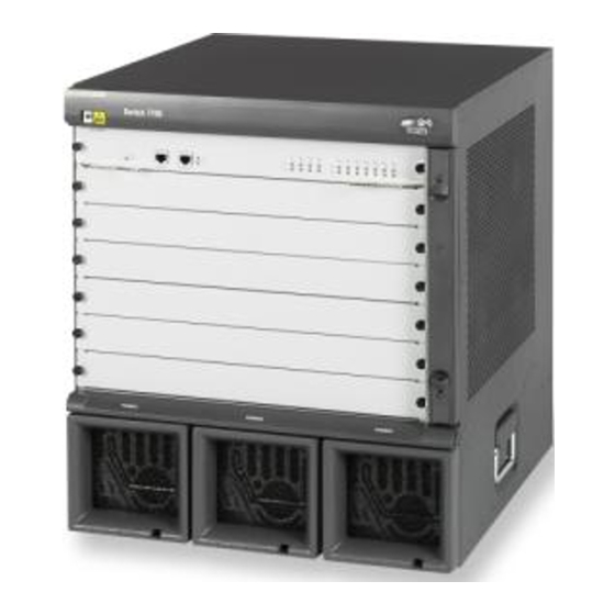
64Gbps. 2.1.2. Modular Hardware Architecture The Switch 7700 can be installed in a standard 19-inch wide cabinet. The chassis includes slots for modules, fan and power supplies. The module area includes one Fabric module slot and 6 I/O module slots. The Fabric module is mandatory. -
Page 10: I/O Module Interfaces
O V E R V I E W 2.1.3. I/O Module Interfaces The Switch 7700 supports I/O modules that offer from 8 to 48 ports, as described in the following list: 8-port 1000BASE-X (GBIC) GE module (8GBIC) (3C16858) 8-port 10/100/1000BASE-T auto-sensing GE module (8BT) (3C16859) -
Page 11: Chapter 3 Switch 7700 Components
The power area is on the bottom of the chassis and supports up to three sources for AC power 3.1.2. Switch Backplane The Switch 7700 backplane is part of the integrated chassis and delivers high-speed data transfer between the Fabric and I/O modules. The backplane bandwidth capacity is 120Gbps. The backplane supports the following functions:... -
Page 12: Fabric Module
C O M P O N E N T S 3.1.3. Fabric Module The Fabric is the core of Switch 7700 system. It has the following functions. Connects the I/O modules through the backplane and forwards Layer 2 and Layer 3... - Page 13 S W I T C H 7 7 0 0 C O M P O N E N T S Attribute Description Connect with character terminal Services supported Connect with local or remote PC serial port and run terminal emulator on PC (a pair of Modems are needed for remote connection) 10/100BASE-TX Ethernet Management Port The Ethernet port can be connected to a computer using an RJ-45 connector for system application downloading...
-
Page 14: Switching I/O Modules
Off — the fan works normally or has not been installed. 3.1.6. Switching I/O Modules The Switch 7700 provides 6 I/O modules slots below the Fabric (FAB64) slot. (See Figure 2-1). The Switch 7700 supports the following I/O modules: 8-port 1000BASEX (GBIC) GE module (8GBIC) (3C16858) - Page 15 S W I T C H 7 7 0 0 C O M P O N E N T S Attribute 48TX 10M half/full duplex Port transmission speed 100M half/full duplex MDI/MDIX auto-sensing Optional cables and maximum The external cables are 4 Category-5 twisted pairs for transmission within 100m. transmission distance IEEE802.3 Compliance...
- Page 16 S W I T C H 7 7 0 0 C O M P O N E N T S Table 11 Attributes of the 8-port 1000BASEX (GBIC) GE Card Attribute 8GBIC MPC850 BootROM 512KB SDRAM 64Mb Dimensions (L x W) 366.7mm x 340mm Maximum power consumption Quantity of GBIC port(s)
- Page 17 S W I T C H 7 7 0 0 C O M P O N E N T S Figure 8 The 8-port 10/100/1000BASE-T GE Card Attributes of the 8BT module are described in Table 14. Table 14 Attributes of the 8BT (3C16859) module Attribute 8BT I/O module (3C16859) MPC850...
- Page 18 S W I T C H 7 7 0 0 C O M P O N E N T S Figure 10 The 24-port 100BASE-FX MMF FE module Table 16 describes the attributes of the 24 FX module. Table 16 Attributes of the 24-port 100BASE-FX MMF FE module Attribute 24FX (3C16861) MPC850...
-
Page 19: Power System
3.1.8. Fan Assembly (3C16856) The fan assembly, shown in Figure 12, is installed on the right side of the Switch 7700. There are 4 120mm fans to cool the system. The fans are directly connected to the backplane through connectors. Operation fault signals are collected and transmitted to the system alarm board through the backplane. - Page 20 Operation environment temperature 0 to 40 C (32 to 104 Operation environment humidity 5% to 85% Table 21 below describes service features of the Switch 7700. Table 21 Switch 7700 service features Service Support Switching capacity of 64Gbps Wire speed Layer 2 switching Packet forwarding rate at 48Mpps Wire speed forwarding (with forwarding delay less than 10µs) for I/O Module ports...
- Page 21 S W I T C H 7 7 0 0 C O M P O N E N T S Service Support Access user authentication complies with IEEE 802.1x Local authentication and RADIUS authentication User hierarchical management and password protection ACL (Access Control List), L2/L3/L4 information filtration (including frame filtration based AAA and Security on port and source/destination MAC address, packet filtration based on source/destination...
-
Page 23: Chapter 4 Preparing For Installation
This chapter describes safety, site requirements, and tools for your Switch 7700 installation. 4.1. Safety Information Please follow local safety regulations when performing any operation with the Switch 7700. Follow the related safety information and special safety instructions provided by 3Com. 3Com bears no responsibility for accidents that occur due to violations of safe operation requirements. -
Page 24: Preventing Electrostatic Discharge Damage
4.1.5. Laser Safety Some I/O modules on the Switch 7700 have optical ports. If no optical connector is connected to the optical ports or if the dust-proof cover has been removed, there might be invisible laser radiation emitted from the port. -
Page 25: Installation Site Requirements
I N S T A L L A T I O N 4.2. Installation Site Requirements The Switch 7700 can only be used indoors. To ensure that the switch works normally and to expand its service life, the installation environment should meet the requirements in the next section, Temperature/Humidity. -
Page 26: Emi Interference
The grounding bar is fixed with combined screws to avoid loosening 4.2.6. Installation Space The Switch 7700 is a complex piece of equipment so it is necessary to make arrangements for the installation position, power supply, and cabling, as shown in Figure 14. -
Page 27: Installation Tools
I N S T A L L A T I O N Figure 14 Switch 7700 placement 4.3. Installation Tools Table 24 provides a list of the tools you need to install the Switch 7700. Table 24 Required installation tools Measure and... -
Page 29: Chapter 5 Installing Hardware
This chapter describes how to install the components of the Switch 7700. 5.1. Installing the Chassis You can install the Switch 7700 in a standard, 19-inch cabinet or on a workbench. 5.1.1. Installing in a Standard Cabinet Before you install the Switch 7700 in a standard cabinet, verify that:... -
Page 30: Connecting The Ground Wire
AC power socket Warning: For surge protection, the AC power should be led through an external protection device into the Switch 7700. 5.5. Installing the Fan Assembly 1. Wear the anti-static wrist strap and take out the fan frame from the pack. -
Page 31: Connecting The Cables
For safety, do not touch any part of the product that is labeled with dangerous voltage labels. 5.6. Connecting the Cables This section describes how to connect console and AUX cables to the Switch 7700. 5.6.1. Console Cable The console cable is an 8-core shielded cable. One end of the cable has a crimped RJ-45 connector, which is plugged into the console port of the switch. -
Page 32: Aux Cable
5.6.2. AUX cable An AUX cable is used for the Switch 7700 remote dial-up configuration using a modem. The AUX cable is an 8-core shielded cable. One end of the cable is an RS-232 RJ-45 connector, which is used to plug into the switch at the console port. -
Page 33: Connecting I/O Module Interface Cables
I N S T A L L I N G H A R D W A R E 5.7. Connecting I/O Module Interface Cables This section describes how to connect electrical and optical cables. 5.7.1. Connecting Electrical Port Cables The 48TX port uses the RJ-45 connector and category-5 twisted pair cable as transmission medium. The 8BT port uses the RJ-45 connector, shown in Figure 18. -
Page 34: Connecting Fiber Connectors
I N S T A L L I N G H A R D W A R E 5.7.2. Connecting Fiber Connectors When connecting fibers, use fiber connectors according to the optical port type of the peer equipment connected to the local network port module. -
Page 35: Post-Installation Checklist
I N S T A L L I N G H A R D W A R E 5.8. Post-installation Checklist Caution: Confirm that you have turned off the power before checking your installation. Improper connections can injure people or damage components of the switch. Table 29 Installation check list Item Normal... -
Page 37: Chapter 6 Configuring And Booting Software
This chapter describes how to configure and boot the Switch 7700. 6.1. Configuration Configure the local terminal and Switch 7700, using Figure 21 as a reference. The terminal (a PC in this example) is connected to the switch console port through a console cable. - Page 38 C O N F I G U R I N G A N D B O O T I N G S O F T W A R E Figure 22 Connection Description dialog box 3. Enter the name of the new connection in the Name field and click OK. The dialog box, shown in Figure 23 displays.
- Page 39 C O N F I G U R I N G A N D B O O T I N G S O F T W A R E Flow control = none Figure 24 COM1 Properties dialog box 5. Click OK. The HyperTerminal dialogue box displays, as shown in Figure 25. 6.
- Page 40 C O N F I G U R I N G A N D B O O T I N G S O F T W A R E Figure 25 HyperTerminal window 7. In the Properties dialog box, select the Settings tab, as shown in Figure 26. 8.
-
Page 41: Booting The Switch 7700
The PC or terminal for configuration has been started The configuration parameters have been set. 6.3.1. Powering up and Booting Turn on the power for the Switch 7700 and run the BootROM program. The terminal displays the following information: Starting.. - Page 42 C O N F I G U R I N G A N D B O O T I N G S O F T W A R E ****************************************** Switch 7700 BOOTROM, Version 300 ****************************************** Copyright(C) 2001-2005 by 3Com Corporation, Inc. Creation date: Mar 25 2003, 09:33:05 CPU type...
- Page 43 B O O T I N G S O F T W A R E The display of these messages indicates the completion of the switch auto-booting. Press Enter and the terminal screen displays: <3Com> You can now begin the configuration for the Switch 7700.
-
Page 45: Chapter 7 Software Maintenance
Chapter 7 Software Maintenance 7.1. BOOT Menu After powering on the Switch 7700, run BootROM program. The terminal displays the following information: Starting..RAM Line..OK System is booting....• SW 7700 BOOTROM, Version 1.00 Copyright© 2001-2005 by 3Com Corporation. Creation date... -
Page 46: Upgrading Software Using Xmodem
S O F T W A R E M A I N T E N A N C E Note: To access the BOOT Menu, press Ctrl+B during the 5 seconds that “Press Ctrl-B to enter Boot Menu...” displays. Within 5 seconds, the system begins program decompression. At this time if you want to access the BOOT Menu, you must reboot the switch. - Page 47 S O F T W A R E M A I N T E N A N C E 2. 19200 3. 38400 4. 57600 5. 115200 0. Exit Enter your choice (0-5):5 5. Select the appropriate download speed. For example, enter 5 to select the download speed as 115200bps. 6.
-
Page 48: Upgrading Software Using Ethernet
Switch 7700 provides the functions of the TFTP client. Note: The Switch 7700 is not shipped with the TFTP Server program. To upgrade using TFTP: 1. Connect the switch to the PC from which the file is downloaded, using the 10BASE-T/100BASE-TX port on the Fabric for upgrading. -
Page 49: Upgrading Software Using Ftp
7.3.2. Upgrading Software Using FTP Through the Ethernet port, the Switch 7700 can serve as an FTP server or client. It provides users with another means to download the system program software and configure the files. Take the Switch 7700 serving as an FTP client as an example. -
Page 50: Lost Passwords
S O F T W A R E M A I N T E N A N C E 4. Enter 1 in the BOOT Menu. 5. Press Enter to access the download program menu. 1. Set TFTP protocol parameter 2. -
Page 51: Chapter 8 Hardware Maintenance
8.2. Replacing Cards The FABRIC and I/O modules of the Switch 7700 can be installed and removed basically in the same way. This section describes the general measures of installing and removing these modules. -
Page 52: Replacing The Fan Assembly
5. Press the ejector levers inward and seat the pin on the handle bar into the positioning hole in the chassis. Warning: Install a new fan soon after removing the old one to ensure that the Switch 7700 works normally. -
Page 53: Chapter 9 System Troubleshooting
9.1.1. No information is displayed on the terminal After the Switch 7700 is powered on, if there is no information displayed on the terminal, check that: The power system is working normally. -
Page 54: Troubleshooting The Fan
S Y S T E M T R O U B L E S H O O T I N G Off — the power fails to work or has not been installed yet. On — the power fails to work. FAIL Off means that the power works normally or has not been installed yet. -
Page 55: Chapter 10 Technical Support
3Com products. The Knowledgebase is updated daily with technical information discovered by 3Com technical support engineers. This complimentary service, which is available 24 hours a day, 7 days a week to 3Com customers and partners, is located on the 3Com Corporation World Wide Web site at: http://www.knowledgebase_3com.com/... -
Page 56: Support From Your Network Supplier
3Com technical support services at the location nearest you. 10.3.1. Email Support Some 3Com regions offer an email support service. To access this service for your region, use the appropriate URL or email address from the list below. - Page 57 North America: 1 800 876 3266 From the Caribbean, Central and South America, call: Antigua 1 800 988 2112 Argentina 0 810 444 3COM Aruba 1 800 998 2112 Bahamas 1 800 998 2112 Barbados 1 800 998 2112 Belize...
-
Page 58: Returning Products For Repair
10.4. Returning Products for Repair Before you send a product directly to 3Com for repair, you must first obtain an authorization number. Products sent to 3Com without authorization numbers will be returned to the sender unopened, at the sender’s expense. - Page 59 T E C H N I C A L S U P P O R T Nicaragua AT&T +800-998-2112 Panama AT&T +800-998-2112 Paraguay 54-11-4894-1888 Peru AT&T +800-998-2112 Puerto Rico 1-800-998-2112 Salvador AT&T +800-998-2112 Trinidad and Tobago 1-800-998-2112 Uruguay AT&T +800-998-2112 Venezuela AT&T +800-998-2112 Virgin Islands...
Need help?
Do you have a question about the Switch 7700 and is the answer not in the manual?
Questions and answers