Table of Contents
Advertisement
Advertisement
Table of Contents

Related Manuals for GRAPHTEC CS600


Summary of Contents for GRAPHTEC CS600
- Page 1 600/ 500/ IMAGE SCANNER USER’S MANUAL MANUAL NO. CS600-UM-154...
-
Page 2: To Ensure Safe And Correct Use
TO ENSURE SAFE AND CORRECT USE • To ensure safe and correct use of your Image Scanner, read this Manual thoroughly before use. • After having read this Manual, keep it in a handy location for quick reference as needed. •... -
Page 3: Safety Precautions
Unplug the power • Request repair by contacting your sales representa- cord from the socket tive or nearest Graphtec vendor. • Never try to perform repair yourself. Repair work by inexperienced personnel is extremely danger- ous. - Page 4 Safety Precautions (Continued) WARNING Do not connect the scanner to a non-rated power supply. • Use of a different supply voltage may result in a fire hazard or electrical shock. Prohibited CAUTION Be sure to ground the earth terminal. • Unless the scanner is grounded, the operator could suffer an electrical shock in case of current leakage.
- Page 5 Safety Precautions (Continued) CAUTION Be careful not to damage the power cord or the interface cable and never use a damaged cord or cable. • Do not use unnecessary force to bend, pull, twist, or bind the cord and cable, place a heavy object Never damage or on them, nor remodel them.
- Page 6 Safety Precautions (Continued) CAUTION Do not install, use, or store the scanner in a loca- tion that does not meet the specified temperature and humidity ranges. • Such location may impair the scanner’s perform- ance and cause the scanner to malfunction or break down.
- Page 7 Safety Precautions (Continued) CAUTION Do not use sharp, pointed articles on the scanner. • Such action may impair the scanner’s performance and cause the scanner to malfunction or break down. Prohibited Do not exert pressure on the scanner. • Such action may impair the scanner’s performance and cause the scanner to malfunction or break down.
-
Page 8: Introduction
• While every effort has been made to provide complete and accurate information, please contact your sales representative or nearest Graphtec vendor if you find any unclear or mistaken information or have other comments or suggestions. • Notwithstanding the stipulation in the preceding paragraph, Graphtec Corporation as- sumes no liability for damages resulting from either the use of the information contained herein or from use of the product. - Page 9 Scanner Configuration CS600-11/CS500-11 CS500-06/IS200-11 Note: The stand is an option for the CS500-06 models Scanner name Model number Remarks CS600-11 CS600-11eN CS600-11eN-PRO CS500-11 CS500-11eN CS500-11eN-PRO USB/Ethernet model CS500-06 CS500-06eN-PRO IS200-11 IS200-11eN IS200-11eN-PRO – viii –...
- Page 10 (Refer to Section 5.1, “Opening and Closing the Top Cover”.) Scanner Warm-up A warm-up period is not usually required for the CS600/CS500/IS200 Series scanners. However, if you plan to scan a color document (in particular a document with many light colors), we recommend that you allow the CS600/CS500/IS200 Series scanners to warm up for 10 minutes before scanning the document.
-
Page 11: Table Of Contents
Contents TO ENSURE SAFE AND CORRECT USE Conventions Used in This Manual ................... i Description of Safety Symbols ....................i Introduction .......................... vii 1. OVERVIEW Features ........................1-1 Unpacking the Scanner ..................... 1-2 2. PREPARATION Assembling the Scanner ................... 2-1 Part Names and Functions .................. - Page 12 6. TROUBLESHOOTING PROCEDURES The scanner is turned on but doesn’t operate at all ..........6-1 The scanner operates improperly after connection to the computer ......6-1 The control panel’s red Error LED is lit ..............6-2 The control panel’s red Error lamp is flashing ............6-3 The document isn’t properly fed to the initial scanning position ........
-
Page 13: Overview
ITA (Intelligent Thickness Adjustment) Function (CS600 Series models only) The CS600 Series models are capable of scanning documents with a thickness of up to a maximum of 20.3 mm. The ITA function performs automatic detection of the document’s thickness, thereby eliminating complex operations and enabling easy loading... -
Page 14: Unpacking The Scanner
After unpacking the Image Scanner, check its outer casing and check that the standard accessories listed below are all present. If you detect a surface flaw or a missing accessory, please promptly contact your sales representative or nearest Graphtec vendor. Standard Accessories Power cable User’s Manual... -
Page 15: Preparation
2. PREPARATION 2.1 Assembling the Scanner The stand is an option for the CS500-06 models. CS600-11/CS500-11 Two persons are required for the assembly operation. Assemble the stand before mounting the scanner unit. (1) Assemble the caster frames and the side stays using the four screws provided. - Page 16 Side cover Rubber feet Fixing plate Fixing plate Coin screw Coin screw Center bar Fixing plate Notch Groove (4) Secure the side stays in place by tightening up the four center bar fixing screws (see (2) above). 2 – 2 CS600/CS500/IS200...
- Page 17 Screw A Screw A Frame 3 (7) Always ensure that you remove the cushion material that is included below the document hold-down unit before using the product. (Refer to Section 5.1, “Opening and Closing '†e Top Cover”.) CS600/CS500/IS200 2 – 3...
- Page 18 (2) Attach the center bar to the side stays temporarily using the four screws provided. Side stay Side stay Center bar Groove Caster Caster Attach the center bar loosely. Tighten the screws securely after the scanner unit has been mounted on the stand. 2 – 4 CS600/CS500/IS200...
- Page 19 Side cover Rubber feet Fixing plate Fixing plate Coin screw Coin screw Center bar Notch Fixing plate Groove (4) Secure the side stays in place by tightening up the four center bar fixing screws (see (2) above). CS600/CS500/IS200 2 – 5...
- Page 20 Screw A Screw A Frame 3 (7) Always ensure that you remove the cushion material that is included below the document hold-down unit before using the product. (Refer to Section 5.1, “Opening and Closing the Top Cover”.) 2 – 6 CS600/CS500/IS200...
-
Page 21: Part Names And Functions
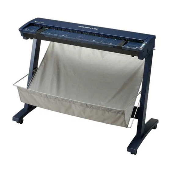
Top cover Control panel Lock Basket Cover sensor Release Release Stand Caster Document guides CS600-11/ICS500-11 Lock Basket Release Release Stand Caster CS500-06/IS200-11 (The stand is an option for the CS500-06 models.) Top cover Open the top cover to clean the document hold-down unit and transparent contact plates. - Page 22 AC line inlet Ethernet connector The above illustration is of the CS600-11/CS500-11 model. Power switch Controls the on/off status of the power supply to the scanner. AC line inlet Connect the power cord’s female plug here. Interface selection switch Used to switch between USB and Ethernet (LAN) connection.
- Page 23 2. PREPARATION Control panel (CS600) POWER LED POWER Unlit : The scanner is turned off. PAPER ERROR Lit (green) : Lights when the scanner is turned on and remains lit while it is operating normally. SCAN Flashing (orange) : Flashes while the scanner is in power-saving mode.
- Page 24 : Lowers the top cover. If the document has been inserted on top of the two paper sensors at the front and rear of the scanner, the document thickness is automatically detected. STOP key Compulsorily stops scanning of the document. 2 – 10 CS600/CS500/IS200...
- Page 25 Feeds the document toward you. When this key is pressed in Scan READY status, the Scan READY status is cancelled and the document is ejected toward the front of the scanner. STOP key Compulsorily stops scanning of the document. CS600/CS500/IS200 2 – 11...
-
Page 26: Attaching The Document Support
2.3 Attaching the Document Support Always ensure that the document support wires are attached to the scanner unit before scanning a document. Note: Drawings of the CS600-11/CS500-11 model are used for the explanations. Normal documents [Up to 1.5 mm thick]... - Page 27 As with the first end, insert the other end of the wire so that it fits into the hidden slot on the lower level. Document support wire end Hidden slot on the lower level CS600/CS500/IS200 2 – 13...
- Page 28 Document support plate (2) Attach the second document support plate in the same manner. Detach the document support plates when moving or packing the scanner. Lift the plates up and out of the slots to detach them. 2 – 14 CS600/CS500/IS200...
- Page 29 2. PREPARATION Attaching the thick document support unit (CS600 only) Use the two screws that are provided with the thick document support unit to attach the unit to the rear of the scanner. Make sure that the document support unit is not attached at an angle. If the unit is not attached correctly, the document may not be fed correctly.
-
Page 30: Preparing To Operate The Scanner
If your scanner does not operate with the USB interface that comes with your computer, or if your computer does not have a USB 2.0 interface, please contact your sales representative or nearest Graphtec vendor for information on supported add-on cards. Recommended environment... -
Page 31: Connecting The Scanner To A Power Supply
3. PREPARING TO OPERATE THE SCANNER 3.2 Connecting the Scanner to a Power Supply Note: Drawings of the CS600-11/CS500-11 model are used for the explanations. Connecting the Power Cable Insert the female plug of the power cord provided into the scanner’s AC line inlet and insert its male plug into an electrical socket supplying AC voltage. - Page 32 Note: The switch is set to USB connection at the time of shipment. If a key is pressed or an operation such as inserting a document is performed while the scanner is in power-saving mode, the scanner returns to the standard operating mode. CS600/CS500/IS200 3 – 3...
-
Page 33: Connecting The Scanner To A Computer
3. PREPARING TO OPERATE THE SCANNER 3.3 Connecting the Scanner to a Computer Note: Drawings of the CS600-11/CS500-11 model are used for the explanations. The scanner can be connected to a computer using the USB interface or the Ethernet interface. - Page 34 Plug the Ethernet cable into the Ethernet connector located on the right-hand side of the scanner unit. Interface selection switch Ethernet connector To the computer Ethernet interface cable When Ethernet connection has been selected, it takes approximately four hours for the scanner to switch to power-saving mode. CS600/CS500/IS200 3 – 5...
-
Page 35: Connecting The Scanner Via An Ethernet Interface
Windows Help for more information. Installing the Network Utility The following procedure assumes that you are using the CS600-11eN/11eN-PRO, CS500- 11eN/11eN-PRO, CS500-06eN-PRO, or the IS200-11eN/11eN-PRO connected via an Ethernet interface as part of your system. The scanner name displayed in the windows is the name of the scanner connected to the computer. - Page 36 3. PREPARING TO OPERATE THE SCANNER (3) Click [Setup]. (4) Click [Device Setup]. The following window appears. (5) Click [Next] to proceed (6) The “Software License Agreement” window appears. Carefully read the provisions of the agreement. CS600/CS500/IS200 3 – 7...
- Page 37 When the setting will be performed from a location that a router is used to access, depending on the type of router used, there may be locations that cannot be searched. In this case, make the setting within the same segment. (8) Click [Next] to display the following window.. 3 – 8 CS600/CS500/IS200...
- Page 38 Please contact your network administrator if you do not know your IP address. Two or more identical IP addresses may cause network problems. (9) Confirm the settings, and then click the [Execute]. (10) This completes the Device Setup operation. CS600/CS500/IS200 3 – 9...
- Page 39 3. PREPARING TO OPERATE THE SCANNER Installing the Graphtec Network Utility (11) Proceed to install the Graphtec Network Utility. Select [Yes], and then click [Finish]. (12) Click [Next]. (13) The “Software License Agreement” window appears. Carefully read the provisions of the agreement.
- Page 40 3. PREPARING TO OPERATE THE SCANNER (15) Click [Next]. Specify the program folder name. (16) Click [Next]. (17) Click [Start] to start the installation procedure. (18) When installation has been completed, click [Finish]. CS600/CS500/IS200 3 – 11...
- Page 41 If Windows XP Service Pack 2 is used to install a network utility, or if Windows XP was updated using Service Pack 2, the following settings must be made. (1) Launch the Control Panel from the [Start] menu. (2) Click the “Security Center” icon. (3) Click “Windows Firewall”. 3 – 12 CS600/CS500/IS200...
- Page 42 (4) Click “Exceptions” to display the following window. Click [Add Program]. (5) Click [Browse], and then select the “Device Setup” program from the CD-ROM. If the CD-ROM is in drive E: Select [E:\English\Network\Utility\Quickset\Gdsetup.exe], and then click [Open]. Click [OK]. CS600/CS500/IS200 3 – 13...
- Page 43 “GDsetup.exe” is added to the “Programs and Services” list. (6) Click [Add Port]. Enter “Graphtec Network Utility” in the Name box, 19540 in the Port number box, and then select “UDP”. (7) Click [OK] to add “Graphtec Network Utility” to the “Programs and Services” list.
- Page 44 3. PREPARING TO OPERATE THE SCANNER Setting up the Graphtec Network Utility (1) Set up the Graphtec Network Utility. Launch the utility from the Graphtec Network Utility created in the Program folder. (2) (2) Register the destination server. When the Utility is launched, the server registration window appears.
- Page 45 When using the CS600-11eN/11eN-PRO, CS500-11eN/11eN-PRO, CS500-06eN- PRO, or IS200-11eN/11eN-PRO connected to an Ethernet interface, be sure to launch the Graphtec Network Utility and click the [Connect] button. Furthermore, when you have finished using the scanner, click the [Disconnect] button to put the scanner in a status that enables it to be used with other computers.
- Page 46 Set the browser’s proxy server to off when performing the initialization settings. (1) Launch Internet Explorer. (2) Enter “http://scanner IP address/ja/index/htm” in the Address bar at the top of the screen. Example: http://192.168.21.123/ja/index/htm (3) Click “Factory Default”. CS600/CS500/IS200 3 – 17...
- Page 47 (4) Enter “root” in the User name box and then click [OK]. (User name: root; Password: blank box) (5) The “Do you wish to load the factory default?” window appears. Click [Yes]. (6) The screen shown below is displayed when the setting has been made. 3 – 18 CS600/CS500/IS200...
- Page 48 (7) Restart the network board. Click “Relaunch Network Scanner” to display the “Are you sure to restart this Network Scanner?” window. Click [Yes]. (8) The following window is displayed after the setting has been made. (9) This completes the initialization of the scanner’s network environment. CS600/CS500/IS200 3 – 19...
-
Page 49: Installing The Driver Software
Windows with administrator rights. Consult your Windows 2000 or Windows XP manual for more information. For Windows 2000 The following procedure assumes that you are using the CS600-11 connected via the USB interface. The scanner name displayed in the windows is the name of the scanner connected to the computer (CS600-11 is used in this section). - Page 50 (5) Select the check box entitled “Specify a location” and click Next. Click [Browse] and select the DRIVER folder in the CD-ROM drive or enter a CD- ROM drive name and \DRIVER using the keyboard. Example: For drive E, enter “E:\DRIVER.” CS600/CS500/IS200 3 – 21...
- Page 51 Click [Yes] to continue the installation. (8) The screen shown below is displayed when the wizard has finished installing the driver. Click the [Finish] button. (9) The Windows 2000 desktop appears, and the scanner is recognized by the computer. 3 – 22 CS600/CS500/IS200...
- Page 52 3. PREPARING TO OPERATE THE SCANNER For Windows XP The following procedure assumes that you are using the CS600-11 connected via the USB interface. The scanner name displayed in the windows is the name of the scanner connected to the computer (CS600-11 is used in this section).
- Page 53 \DRIVER using the keyboard. Example: For drive E, enter “E:\DRIVER.” (5) When you click [Next] the wizard will start searching for the driver. (6) The screen shown below is displayed. Click [Continue Anyway] to continue the installation. 3 – 24 CS600/CS500/IS200...
- Page 54 (7) The screen shown below is displayed when the wizard has finished installing the driver. Click the [Finish] button to close the “Welcome to the Found New Hardware” wizard. (8) The Windows XP desktop appears, and the scanner is recognized by the computer. CS600/CS500/IS200 3 – 25...
-
Page 55: Checking The Interface Connection
3.6 Checking the Interface Connection For Windows 2000 The following procedure assumes that the CS600-11 is connected in your system. The scanner name displayed in the windows is the name of the scanner connected to the computer (CS600-11 is used in this section). - Page 56 3. PREPARING TO OPERATE THE SCANNER For Windows XP The following procedure assumes that the CS600-11 is connected in your system. The scanner name displayed in the windows is the name of the scanner connected to the computer (CS600-11 is used in this section).
-
Page 57: Installing The Scanning Master 21+ Application
3. PREPARING TO OPERATE THE SCANNER 3.7 Installing the Scanning Master 21+ Application The Scanning Master 21+ “OPS112” is a software application for using a Graphtec scanner to scan image data. Operating Environment Windows 2000 Professional/XP Professional/XP Home Edition Installation Procedure (The following steps are explained using the Windows 2000.) -
Page 58: Loading A Document
4.1 Compatible Document Types Because the scanner scans a document while feeding it, the document types that it can scan are subject to the following restrictions. Compatible Media Widths for Scanning Documents with a maximum width of 1066 mm (CS600-11/CS500-11/IS200-11) Size Size ANSI 210 mm ×... - Page 59 4. LOADING A DOCUMENT Compatible Media Thicknesses for Scanning The CS600 scanner cannot scan a document that is thicker than 0.8 inches (20.3 mm). When thick paper is scanned, the material used and the condition of the document may affect the quality and precision of the scanned results.
- Page 60 The document is scanned in the standard paper size determined from the automatically detected document width. Automatic detection—ISO series Automatic detection—ANSI series Automatic detection—ARCH series Automatic detection—DIN series The document is scanned in the paper size of the respective series as determined from the automatically detected document width. CS600/CS500/IS200 4 – 3...
- Page 61 4. LOADING A DOCUMENT 4.2 Loading a Document Document Loading Flowchart (CS600 only) Start document loading Is the document thicker than 1.5 mm Attach the document Attach the document support wires. support unit. (See“Section 2.3, Attaching the (See “Section 2.3, Attaching the Document Supports”...
- Page 62 Document edge This ensures that the document does not get damaged if it is fed at an angle. Document guides Document-scanning table The above illustration is of the CS600-11/CS500-11 model. CS600/CS500/IS200 4 – 5...
- Page 63 • Load the document in the center of the scanner, as the document may be fed in at an angle and not scanned correctly if it is significantly off-center. (CS600 only) • When loading a thick document, make sure that there is sufficient space in front of and behind the scanner.
- Page 64 4. LOADING A DOCUMENT Detecting the thickness of the document to be scanned (CS600 only) [When scanning a thick document (thicker than 1.5 mm)] (1) Press the ITA key to switch to ITA mode (the ITA LED lights). (2) When the document is placed over the paper sensor as shown below and inserted into the recess, the top cover starts to rise automatically after approximately two seconds.
- Page 65 (3) When the ITA LED stops flashing, remove your finger from the REVERSE key. (4) With the ITA LED in the unlit status, press the ITA key to switch to READY mode (the READY LED lights). 4 – 8 CS600/CS500/IS200...
-
Page 66: Handling Documents According To Their Material And Thickness
• The end of the document is not scanned. Such problems may be avoided by taking the following corrective measures. • Lower the scanning speed. • Support the document at the front and the back of the scanner. CS600/CS500/IS200 4 – 9... -
Page 67: Distance Correction
The values entered here must be within the range of the distance correction. (6) Click the OK button to calculate the correction value. The distance will be corrected the next time a document is scanned. 4 – 10 CS600/CS500/IS200... -
Page 68: Using The Carrier Sheet
Transparent sheet (front surface) Target document (the surface to be scanned faces up) White surface (background surface) The above illustration is of the CS600-11/CS500-11 model. • When handling the carrier sheet, be very careful not to scratch it or otherwise damage it. -
Page 69: Daily Maintenance
90 degrees. Top cover Open levers The above illustration is of the CS600-11/CS500-11 model. (3) Close the top cover until the left and right latches on the top cover lock into position, making sure that you don’t get your fingers caught. -
Page 70: Cleaning The Document Hold-Down Unit
Latch Latch The above illustration is of the model. CS600-11/CS500-11 (3) Wipe clean the underside of the document hold-down unit (see below) using a soft cloth that has been soaked in water or diluted neutral detergent and thoroughly wrung out. -
Page 71: Cleaning The Image Sensors
Transparent contact plates The above illustration is of the model. CS600-11/CS500-11 (4) Completely remove any moisture on the transparent contact plates by wiping them off again using a soft, dry cloth. (5) Close the top cover as described in Section 5.1 “Opening and Closing the Top Cover”. -
Page 72: Cleaning The Paper Sensors
Paper sensors The above illustration is of the model. CS600-11/CS500-11 (4) Close the top cover as described in Section 5.1 “Opening and Closing the Top Cover”. Take care not to get your fingers caught in the cover. Use a cotton swab or something equally soft to gently wipe the paper sensors. Do not use any chemicals to clean the sensors. -
Page 73: Removing A Jammed Document
Select the procedure that is appropriate for your scanner model and/or document thickness. CS600 (thin document up to 1.5 mm thick)/CS500/IS200 (1) Turn off the scanner. (2) Open the top cover as described in Section 5.1 “Opening and Closing the Top Cover”. - Page 74 5. DAILY MAINTENANCE CS600 (documents thicker than 1.5 mm) (1) Press the ITA key to switch the scanner to ITA mode (the ITA LED lights). (2) Hold down the FORWARD key. The top cover will start to rise. The ITA LED flashes while the cover is rising.
-
Page 75: Calibration
A low-resolution monitor will make it difficult to discern any problem areas. Calibration of the document-thickness settings for the CS600 scanner is performed in the status that is set for thin documents. (See “Detecting the thickness of the document to be scanned”... -
Page 76: Calibration Sheet
(1) Connect the scanner to the computer. Switch on the scanner, then switch on the PC. (2) Launch the Scanner Adjustment program (as described earlier). (3) Select Model Setup on the Scanner menu. (4) Select the connected scanner and click the [OK] button. 5 – 8 CS600/CS500/IS200... - Page 77 (8) Clicking the [OK] button begins calibration. (9) Calibration ends after approximately 10 minutes. Click the [OK] button to complete calibration. (10) To check the calibration results, click the Confirm button in the Calibration menu (shown in step (5) above). CS600/CS500/IS200 5 – 9...
- Page 78 (17) Return to step (10) and verify the calibration results. If you perform the calibration adjustment several times with no discernible results, there may be a problem with the scanner itself. In this case, please contact your Graphtec vendor. 5 – 10 CS600/CS500/IS200...
- Page 79 Graphtec vendor. Color correction sheet (for the CS600-11/CS500-11/IS200-11eN-PRO models) Color correction sheet (for the CS500-06 model) (1) Select Color Correction on the Scanner menu.
- Page 80 (6) Click in the center of the color tile indicated by the numbers 1 to 6 (1 to 4 in the case of the CS500-06 model). Align the cursor crosshairs with the printed lines at the sides of the tile. CS600-11/CS500-11/IS200-11eN-PRO models Cursor lines (red) Align with the printed lines, then click.
- Page 81 (11) Click the Fit icon to display the entire image, and check whether there is any discrepancy in color. If there is no discrepancy, color correction is complete. Click the Close button. If there is still some color discrepancy after performing Color Correction, repeat steps (6) through (11). CS600/CS500/IS200 5 – 13...
-
Page 82: Troubleshooting Procedures
Are both the USB and Ethernet Both cables cannot be connected at the same cables connected? time. Disconnect one of the cables. Is the Graphtec Network Utility connected? Connect the Graphtec Network Utility. (when using the Ethernet connection) Is the Graphtec Network Utility installed? Install the Graphtec Network Utility. -
Page 83: The Control Panel's Red Error Led Is Lit
Scanning Master 21+ is set to “USB” when you are using a USB interface. Consult the Scanning Master 21+ user’s manual for further information. “Communication error” is displayed for the Graphtec Network Utility status, and connection cannot be performed. Cause Remedy... -
Page 84: The Control Panel's Red Error Lamp Is Flashing
(the surface to be scanned) facing down. The scanning conditions set were Set the scanning conditions again (they can be inappropriate for the document. controlled from the scanning software provided). CS600/CS500/IS200 6 – 3... -
Page 85: The Image Quality Has Dropped
Moreover, fine adjustment to correct such deviation can be performed using the driver software if the deviation causes are overlapped or missing data. Overlapped data Original document Data overlaps Missing data Original document Data is missing Deviation due to scanner specifications Original document Deviation caused by specifications 6 – 4 CS600/CS500/IS200... - Page 86 Document feed direction Sensor 2 Sensor 3 Sensor 1 Markings on the document scanning table Document feed direction Because the document is loaded face down, Sensor 1 is the leftmost sensor in the driver software’s display windows. CS600/CS500/IS200 6 – 5...
-
Page 87: Smudges Not Appearing In The Original Document Appear In The Scanned Data
(Scanning Master 21+) provided with for a document of a different paper type. your scanner, select the Distance Correction The scanning precision varies according function to adjust the precision. to the type of document. 6 – 6 CS600/CS500/IS200... -
Page 88: Stripes Or Moiré Patterns Which Are Not In The Original Document Appear In The Scanned Data
Cause Remedy The scanner’s image scanning quality has Run the “Scanner Adjustment Program” deteriorated. (see Section 5.6, “Calibration”), and perform calibration. You are using a carrier sheet with a color Don’t use the carrier sheet. document. CS600/CS500/IS200 6 – 7... -
Page 89: The Document Cannot Be Fed Correctly
The thick document that has been inserted Press the ITA key to raise the top cover. is slipping, and cannot be fed. (CS600) Remove the document, and then reload it. 6.16 “Document size cannot be acquired” is displayed Cause... -
Page 90: The Document Stops During The Thickness-Detection Process
Foreign matter is obstructing the document Remove the document, and then remove the movement. foreign matter. The safety sensor has been activated. The paper jam sensor has been activated. Press the FORWARD key to raise the top cover. CS600/CS500/IS200 6 – 9... -
Page 91: Appendix A. Optional And Miscellaneous Items
APPENDIX A. OPTIONAL AND MISCELLANEOUS ITEMS APPENDIX A. OPTIONAL AND MISCELLANEOUS ITEMS Optional items can be obtained from your sales representative or nearest Graphtec vendor. Optional items Code Item name Software to upgrade OPS112 Scanning Master 21+ to OPS115 Scanning... -
Page 92: Appendix B. Standard Specifications
Up to 20.3 mm or less (including the carrier sheet) Optical resolution 600 dpi Interpolated resolution CS600-11eN: 50 to 800 dpi, in 1-dpi increments CS600-11eN-PRO: 50 to 4800 dpi, in 1-dpi increments Main scanning system Contact image sensor system (Five A4 sensors in a zigzag pattern) - Page 93 The precision figures above were measured under the operating conditions described below. • Special test chart used : Mylar sheet #200 • Guaranteed precision conditions : Temperature 20°C ±3°C; Humidity: 60% ±10% RH *4 The USB 2.0 and Ethernet interfaces cannot be used at the same time. B – 2 CS600/CS500/IS200...
- Page 94 The precision figures above were measured under the operating conditions described below. • Special test chart used : Mylar sheet #200 • Guaranteed precision conditions : Temperature 20°C ±3°C; Humidity: 60% ±10% RH *4 The USB 2.0 and Ethernet interfaces cannot be used at the same time. CS600/CS500/IS200 B – 3...
- Page 95 • Special test chart used : Mylar sheet #200 • Guaranteed precision conditions : Temperature 20°C ±3°C; Humidity: 60% ±10% RH *4 The USB 2.0 and Ethernet interfaces cannot be used at the same time. *5 PRO only. B – 4 CS600/CS500/IS200...
-
Page 96: Appendix C. External View
APPENDIX C. EXTERNAL VIEW APPENDIX C. EXTERNAL VIEW External Dimensions CS600-11/CS500-11 1205 IS200-11 1205 CS500-06 Unit : mm Dimensional precision error : ± 5 mm CS600/CS500/IS200 C – 1... -
Page 97: Index
Basket ............. 2-7 CS500/IS200 ........2-11 CS600 ..........2-10 Calibration adjustment ......5-8 Calibration sheets ........1-2 Graphtec network utility ......3-15 Carrier sheet ......... 1-2, 4-11 Casters ............ 2-7 Cleaning paper ........1-2 Image sensors, Cleaning ......5-3 Color correction ........5-11 Initializing the scanner ...... - Page 98 Power on and off ........3-3 Power switch ........... 2-8 Power-saving mode ......... 3-3 READY LED ..........2-9 REVERSE key CS500/IS200 ........2-11 CS600 ..........2-10 SCAN key CS500/IS200 ........2-11 CS600 ..........2-10 Software CD-ROM ........1-2 Stand ............2-7 Standard accessories ......
- Page 99 The specifications, etc., in this manual are subject to change without notice. CS600-UM-154 May 10, 2007 1st edition-01 GRAPHTEC CORPORATION...
- Page 100 503-10 Shinano-cho, Totsuka-ku, Yokohama 244-8503, Japan Tel : +81 (045) 825-6250 Fax : +81 (045) 825-6396 Email : info@graphteccorp.com Web : www.graphteccorp.com Printed in Japan 641600880...
Need help?
Do you have a question about the CS600 and is the answer not in the manual?
Questions and answers