Sign In
Upload
Download
Table of Contents
Contents
Add to my manuals
Delete from my manuals
Share
URL of this page:
HTML Link:
Bookmark this page
Add
Manual will be automatically added to "My Manuals"
Print this page
×
Bookmark added
×
Added to my manuals
Manuals
Brands
GRAPHTEC Manuals
Scanner
CSX500 SERIES
User manual
GRAPHTEC CSX500 Series User Manual
Image scanner
Hide thumbs
Also See for CSX500 Series
:
User manual
(84 pages)
1
2
3
4
5
6
7
8
9
10
11
12
Table Of Contents
13
14
15
16
17
18
19
20
21
22
23
24
25
26
27
28
29
30
31
32
33
34
35
36
37
38
39
40
41
42
43
44
45
46
47
48
49
50
51
52
53
54
55
56
57
58
59
60
61
62
63
64
65
66
67
68
69
70
71
72
73
74
75
76
77
78
79
80
81
82
83
84
page
of
84
Go
/
84
Contents
Table of Contents
Troubleshooting
Bookmarks
Table of Contents
To Ensure Safe and Correct Use
Conventions Used in this Manual
Description of Safety Symbols
Safety Precautions
Installation Precautions
Power Supply Precautions
Handling Precautions
Maintenance and Inspection Precautions
Copyright
International ENERGY STAR® Program
Introduction
Registered Trademarks
Scanner Warm-Up
Usage Precautions
Table of Contents
Chapter 1 Before Using the Scanner
Checking the Contents of the Package
Part Names and Functions
Front View/Control Panel
Rear View
Assembling the Scanner
Attaching the Document Support Plates
Attaching and Using the Cable Clamp
Chapter 2 Connection and Preparations
Connecting to the Power Supply
Turning the Power on and off
Turning the Power on
Turning the Power off
Notes on the Power-Saving Mode
System Requirements
Connecting the Scanner to a Computer
USB Connection
Network Connection (CSX550-09 Only)
Installing the Scanner Driver Software
For Windows Vista
For Windows XP
Installing the Scanning Master Pro Color Application
Operating Environment
Installation Procedure
Network Connection (CSX550-09 Only)
Installation Procedure
Device Setup Settings
Installing the Graphtec Network Utility
Setting up the Graphtec Network Utility
How to Initialize the Settings
Chapter 3 Loading a Document
Compatible Document Types
Compatible Media Widths for Scanning
Compatible Media Lengths for Scanning
Compatible Document Thicknesses for Scanning
Compatible Media Grades for Scanning
Loading a Document
How to Use the Document Guides
Handling Documents According to Their Material and Thickness
Distance Correction
Adjustment Method
Using the Carrier Sheet
Chapter 4 Daily Maintenance
Opening and Closing the Top Cover
Opening the Top Cover
Closing the Top Cover
Cleaning the Feed Rollers
Cleaning the Document Support Rollers
Cleaning the Gap Rollers
Cleaning the Push Rollers
Cleaning the Image Sensors (Transparent Contact Plates)
Cleaning the Sensors
Removing a Jammed Document
Scanner Adjustment
Preparation and Checks
Launching the Scanner Adjustment Program
Calibration
Chapter 5 Troubleshooting Procedures
The Scanner Is Turned on but Doesn't Operate at All
The Scanner Operates Improperly after Connection to the Computer
The Control Panel's Red ERROR LED Is Lit
The Control Panel's Red ERROR LED Is Flashing
The Document Isn't Properly Fed to the Initial Scanning Position
The Scanned Image Data Is Completely White or Completely Black
The Image Quality Has Dropped
The Scanned Data Is Incorrectly Aligned
Smudges Not Appearing in the Original Document Appear in the Scanned Data
The Color Intensity of the Image Data Differs
The Document Length Differs from the Scanned Data Length
Stripes or Moire Patterns Which Are Not in the Original Document Appear in the Scanned Data
The Scanned Image Data Is Distorted
The Scanned Image Data Is Patchy
The Document Cannot be Fed Correctly
Automatic Deskew Is Not Performed Correctly
Appendix
Appendix A Options and Consumables
Appendix B Specifications
Appendix C External Dimensions
Index
Advertisement
Quick Links
1
Network Connection (Csx550-09 Only)
Download this manual
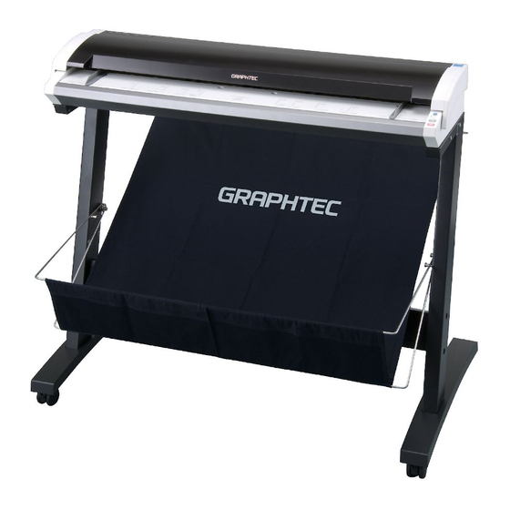
500
CSX
SERIES
IMAGE SCANNER
USER'S MANUAL
MANUAL NO.CSX500-UM-152
www.delinit.by
Table of
Contents
Previous
Page
Next
Page
1
2
3
4
5
Advertisement
Table of Contents
Need help?
Do you have a question about the CSX500 Series and is the answer not in the manual?
Ask a question
Questions and answers
Related Manuals for GRAPHTEC CSX500 Series
Scanner GRAPHTEC CSX500 SERIES User Manual
Image scanner (84 pages)
Scanner Graphtec CSX300-09 User Manual
Image scanner (63 pages)
Scanner GRAPHTEC CSX510-09 User Manual
Image scanner (84 pages)
Scanner GRAPHTEC CSX530-09 User Manual
Image scanner (84 pages)
Scanner GRAPHTEC CSX550-09 User Manual
Image scanner (84 pages)
Scanner GRAPHTEC CS1000EV User Manual
Color image scanner (75 pages)
Scanner GRAPHTEC CS2000 User Manual
Color image scanner (79 pages)
Scanner GRAPHTEC CS2000 Service Manual
Color image scanner (138 pages)
Scanner Graphtec CS510 SERIES Service Manual
Image scanner (122 pages)
Scanner GRAPHTEC CS610 User Manual
Image scanner (100 pages)
Scanner Graphtec CS600 User Manual
Image scanner (100 pages)
Scanner Graphtec CS500 User Manual
Image scanner (78 pages)
Scanner GRAPHTEC CS500 Series Service Manual
Image scanner (116 pages)
Scanner Graphtec CS1000 Service Manual
Color image scanner (149 pages)
Scanner GRAPHTEC CS400 User Manual
Color image scanner (73 pages)
Scanner GRAPHTEC CS610-11eN Service Manual
Color image scanner (132 pages)
This manual is also suitable for:
Csx510-09
Csx530-09
Csx550-09
Table of Contents
Print
Rename the bookmark
Delete bookmark?
Delete from my manuals?
Login
Sign In
OR
Sign in with Facebook
Sign in with Google
Upload manual
Upload from disk
Upload from URL


Need help?
Do you have a question about the CSX500 Series and is the answer not in the manual?
Questions and answers