Table of Contents
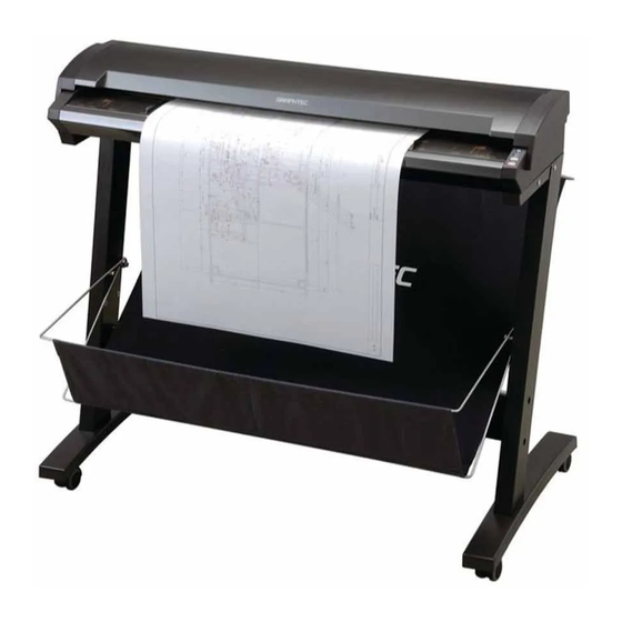
Advertisement
Advertisement
Table of Contents

Related Manuals for GRAPHTEC CSX300-09


Summary of Contents for GRAPHTEC CSX300-09
- Page 1 300-09 IMAGE SCANNER USER’S MANUAL MANUAL NO. CSX300-UM-151...
-
Page 2: To Ensure Safe And Correct Use
TO ENSURE SAFE AND CORRECT USE • To ensure the safe and correct use of your Image Scanner, read this manual thoroughly prior to use. • After reading this manual, store it in a safe place for reference as necessary. •... -
Page 3: Safety Precautions
Graphtec representative. Caution Do not use the scanner in an unstable location such as on a slope or a location that is subject to a lot of vibration. - Page 4 Do not exert pressure on the scanner. • Such action may impair the scanner’s performance and cause the scanner to malfunction or break down. • Such action could cause injury to the operator. Avoid installing the scanner in any of the following locations.
-
Page 5: Power Supply Precautions
Power Supply Precautions Warning Do not damage the power cable, or modify it in any way. Moreover, do not place heavy objects on the power cable, pull on the cable, or bend it excessively. • There may be current leakage from the damaged parts, resulting in a fire hazard or electric shock. - Page 6 Caution When disconnecting the power cable, be sure to hold on to the plug, and not pull on the cable itself. • Pulling on the cable will expose the core wires, or cause damage such as broken wires. Current leakage from the exposed or damaged areas may result in a fire hazard or electric shock.
-
Page 7: Handling Precautions
•Use of the scanner in such status may result in a fire hazard or electric shock. •Request repair by contacting the store where you purchased your scanner or your nearest Graphtec representative. •Never try to perform repair yourself. Repair work by inexperienced personnel is extremely dangerous. - Page 8 Graphtec representative. Do not insert your hands inside the scanner during a scanning operation or when a document is being fed.
-
Page 9: Maintenance And Inspection Precautions
Maintenance and Inspection Precautions Warning Be sure to turn off the power and remove the power plug from the power outlet before performing any cleaning operations. •Failure to do so may result in a fire hazard or electric shock. Moreover, there is a risk of injury if the scanner starts to move during a cleaning operation. - Page 10 WARNING Only computers or peripherals (computer input/output devices, terminals, printers, etc.) certified as complying with the limits for a Class B digital device, pursuant to Part 15 of the FCC Rules, may be attached to this product when this product is operated in a residential environment.
-
Page 11: Introduction
(3) While every effort has been made to provide complete and accurate information, please contact your nearest Graphtec representative if you find any unclear or erroneous information or wish to make other comments or suggestions. (4) Notwithstanding the stipulation in the preceding paragraph, Graphtec Corporation assumes no liability for damages resulting from either the use of the information contained herein or the use of the product. -
Page 12: Usage Precautions
(See Section 4.1, “Opening and Closing the Top Cover”.) Scanner warm-up A warm-up period is not usually required for the CSX300-09. However, if you plan to scan a color document (in particular a document with many light colors), we recommend that you allow the... -
Page 13: Table Of Contents
CONTENTS TO ENSURE SAFE AND CORRECT USE ................... i SAFETY PRECAUTIONS Installation Precautions ....................ii Power Supply Precautions .................... iv Handling Precautions ....................vi Maintenance and Inspection Precautions ..............viii INTRODUCTION Notes on this Manual ...................... I Registered Trademarks ....................I Copyright ........................ - Page 14 Handling Documents According to their Material and Thickness ........3-4 Distance Correction ......................3-5 Using the Carrier Sheet ....................3-6 CHAPTER 4 DAILY MAINTENANCE Opening and Closing the Top Cover ................4-1 Cleaning the Feed Rollers ....................4-2 Cleaning the Document support Rollers ................ 4-3 Cleaning the Gap Rollers ....................
-
Page 15: Chapter 1 Before Using The Scanner
1.1 Checking the Contents of the Package Check to confirm that all of the items shown below are present. If any item is missing, promptly contact the store where you purchased your scanner or your nearest Graphtec representative. Power cable ...1 Scanner unit ...1... -
Page 16: Part Names And Functions
1.2 Part Names and Functions Front View/Control Panel (2) Paper sensors Control Panel (5) POWER button/LED (4) Document guides (6) PAPER LED (7) ERROR LED (1) Top cover (8) EJECT key (9) STOP key (3) Top cover open levers Front View (1) Top cover ....... -
Page 17: Rear View
(9) STOP key ...... Compulsorily stops scanning/feeding of the document. If the ERROR LED flashes when the top cover is in the closed status, press this key to suspend the scanning operation and check whether a paper jam has occurred. Rear View (13) Document support plates (10) USB connector... -
Page 18: Assembling The Scanner
1.3 Assembling the Scanner Please see the separate Stand Assembly Instruction Manual for instructions on how to assemble the stand. Attaching the document support plates Always be sure to install the document support plates, irrespective of the type of documents to be scanned. - Page 19 (2) Wipe the area once again with a soft, dry cloth to thoroughly remove any traces of moisture. (3) Peel off the adhesive sticker on the rear of the clamp and then attach the clamp to the scanner. Cable clamp Using the clamp (1) Pull up the latch at the top of the cable clamp to open the clamp.
-
Page 20: Chapter 2 Connection And Preparations
CHAPTER 2 CONNECTION AND PREPARATIONS 2.1 Connecting to the Power Supply Connect one end of the power cable provided to the scanner’s power inlet and the other end to an AC power outlet of the rated supply voltage. AC power outlet Power inlet Power cable Caution... -
Page 21: Turning The Power On And Off
2.2 Turning the Power On and Off The LED (blue) on the [POWER] button changes as follows to indicate the scanner's power supply status. • Unlit: The scanner is turned off. • Lit: The scanner is turned on. • Flashing: Flashes when the scanner is in power-saving mode. Turning the Power On (1) Connect the power cable. -
Page 22: Notes On The Power-Saving Mode
Notes on the power-saving mode The scanner automatically switches to power-saving mode (the blue LED on the power button flashes) after approximately 12 minutes have elapsed without a document being loaded in the scanner. To return the scanner to normal status (Local status), press either the [STOP] or the [EJECT] key. -
Page 23: System Requirements
2.3 System Requirements The minimum system requirements for running the scanner’s hardware and software are listed below. • Operating system: Windows 2000 Professional, XP Professional, XP Home Edition, or Vista • CPU: Pentium III, 1 GHz • Memory: 256 MB or more •... -
Page 24: Connecting The Scanner To A Computer
2.4 Connecting the Scanner to a Computer USB Connection A USB cable is used to connect the scanner to the computer, via the respective USB interface connectors. The connectors at the computer and scanner ends of the USB cable have different shapes. Make sure that the cable is oriented correctly before making the connection. -
Page 25: Installing The Driver Software
2.5 Installing the Driver Software heckpoint The procedure outlined below is based on the requirement that you are logged on to Windows with administrator rights. Consult your Windows manual and Windows Help for more information. For Windows Vista (1) Use the USB cable to connect the scanner to the computer, and then turn on the computer. - Page 26 (8) The screen shown below is displayed. Click "Browse my computer for driver software (advanced)". (9) The screen shown below is displayed. Click [Browse] and either select the [DRIVER] folder in the CD-ROM drive or enter a CD-ROM drive name and \DRIVER using the keyboard.
-
Page 27: For Windows Xp
(12) The screen shown below is displayed when the wizard has finished installing the driver. Click the [Close] button to close the "Found New Hardware" wizard. (13) The Windows Vista desktop appears, and the scanner is recognized by the computer. For Windows XP (1) Use the USB cable to connect the scanner to the computer, and then turn on the computer. - Page 28 (6) The screen shown below is displayed. Select the option “Search for the best driver in these locations” and select the check box entitled “Include this location in the search.” Click [Browse] and either select the [DRIVER] folder in the CD-ROM drive or enter a CD- ROM drive name and \DRIVER using the keyboard.
-
Page 29: For Windows 2000
For Windows 2000 (1) Use the USB cable to connect the scanner to the computer, and then turn on the computer. (2) When Windows starts up, insert the CD-ROM supplied with the scanner into the CD- ROM drive. (3) Turn on the power to the scanner. (4) The screen shown below appears. - Page 30 (8) The screen shown below is displayed when the wizard has finished searching. Click [Next]. (9) The screen shown below is displayed. Read the explanation and make sure that you understand the contents. To continue the installation, click [Yes]. (10) The screen shown below is displayed when the wizard has finished installing the driver. Click the [Finish] button.
-
Page 31: Checking The Interface Connection
(1) Launch the Control Panel using the [Start] menu on the Windows desktop. (2) Click "Hardware and Sound" to display the screen shown below. (3) Click "Scanners and Cameras" to display the screen shown below. Check that "Graphtec CSX300-09" is displayed here. 2-12... -
Page 32: For Windows Xp
(2) The screen shown below is displayed when you click on the “Printers and Other Hardware” icon. (3) The screen shown below is displayed when you click on the “Scanners and Cameras” icon. Check that “Graphtec CSX300-09” is displayed here. 2-13... -
Page 33: For Windows 2000
For Windows 2000 (1) Launch the Control Panel using the [Start] menu on the Windows desktop. (2) The screen shown below is displayed when you click on the “Scanners and Cameras” icon. Check that “Graphtec CSX300-09” is displayed here. 2-14... -
Page 34: Installing The Scanning Master 21+ Application
2.7 Installing the Scanning Master 21+ Application Scanning Master 21+ "OPS112" is a software application for using a Graphtec scanner to scan image data. Operating environment Windows 2000 Professional, XP Professional, XP Home Edition or Vista Installation procedure The following steps are explained using the Windows 2000 screens. -
Page 35: Chapter 3 Loading A Document
Compatible Document Thicknesses for Scanning The CSX300-09 cannot scan a document that is thicker than 1.6 mm. When using the carrier sheet that is available as an option, ensure that the combined thickness of both the document and carrier sheet does not exceed 1.6 mm. -
Page 36: Loading A Document
3.2 Loading a Document How to use the document guides Insert the document (the surface to be scanned) face up into the scanner until the top edge of the document contacts the feed rollers. At this time, make sure that the document is straight and that it is centered in the scanner. - Page 37 Caution • The document may not be fed in correctly if it is curled. The carrier sheet that is available as an option should be used for curled documents (see Section 3.5, “Using the Carrier Sheet” for details). • Load the document in the center of the scanner, as the document may be fed in at an angle and not scanned correctly if it is significantly off-center.
-
Page 38: Handling Documents According To Their Material And Thickness
3.3 Handling Documents According to their Material and Thickness The following problems may occur, depending on the thickness and surface condition of the document being scanned. • The document cannot be loaded. • Scanning of the document stops half-way through. •... -
Page 39: Distance Correction
3.4 Distance Correction Corrections to the distance can be achieved using the driver software. The driver software included with your scanner (“Scanning Master 21+”) enables you to perform distance correction from the menu Tool → → → → → Adjust Scanner in order to adjust the scanning accuracy. The adjustment function must be set up when a scanned drawing needs to approximate the accuracy of the original drawing closely. -
Page 40: Using The Carrier Sheet
3.5 Using the Carrier Sheet Use the carrier sheet according to the condition of the document to be scanned. In the case of scanning the following types of media, always place the document in the carrier sheet that is available as an option before loading it into the scanner. •... -
Page 41: Chapter 4 Daily Maintenance
CHAPTER 4 DAILY MAINTENANCE 4.1 Opening and Closing the Top Cover Opening the top cover (1) Turn off the scanner. (2) Using both hands, push up the left and right open levers on the top cover to unlock them. While still holding on to the levers, open the cover fully (approximately 47 degrees). (3) When the top cover is fully open, the fixing stay operates to hold the top cover in place. -
Page 42: Cleaning The Feed Rollers
4.2 Cleaning the Feed Rollers (1) Turn off the scanner. (2) Open the top cover as described in Section 4.1, “Opening and Closing the Top Cover”. (3) While rotating the feed rollers, wipe them clean using a soft cloth that has been moistened with water or a neutral detergent (diluted with water) and firmly wrung out. -
Page 43: Cleaning The Document Support Rollers
4.3 Cleaning the Document support Rollers (1) Turn off the scanner. (2) Open the top cover as described in Section 4.1, “Opening and Closing the Top Cover”. (3) While rotating the document support rollers, wipe them clean using a soft cloth that has been moistened with water or a neutral detergent (diluted with water) and firmly wrung out. -
Page 44: Cleaning The Gap Rollers
4.4 Cleaning the Gap Rollers (1) Turn off the scanner. (2) Open the top cover as described in Section 4.1, “Opening and Closing the Top Cover”. (3) While rotating the gap rollers, wipe them clean using a soft cloth that has been moistened with water or a neutral detergent (diluted with water) and firmly wrung out. -
Page 45: Cleaning The Push Rollers
4.5 Cleaning the Push Rollers (1) Turn off the scanner. (2) Open the top cover as described in Section 4.1, “Opening and Closing the Top Cover”. (3) While rotating the push rollers, wipe them clean using a soft cloth that has been moistened with water or a neutral detergent (diluted with water) and firmly wrung out. -
Page 46: Cleaning The Image Sensors (Transparent Contact Plates)
4.6 Cleaning the Image Sensors (Transparent Contact Plates) The scanner’s image quality drops when the transparent contact plates over the image sensors become dirty, so clean the image sensors whenever necessary. (1) Turn off the scanner. (2) Open the top cover as described in Section 4.1, “Opening and Closing the Top Cover”. (3) As shown below, wipe off any soiled areas on the transparent contact plates using a soft cloth that has been moistened with water or a neutral detergent (diluted with water) and firmly wrung out. -
Page 47: Cleaning The Sensors
4.7 Cleaning the Sensors Accumulated dust on the paper sensors or on the document size detection sensors may prevent the document from being scanned correctly. The sensors must be cleaned when necessary. (1) Turn off the scanner. (2) Open the top cover as described in Section 4.1, “Opening and Closing the Top Cover”. (3) Wipe the two paper sensors or the five document size detection sensors using a cotton swab. -
Page 48: Removing A Jammed Document
4.8 Removing a Jammed Document If a document becomes jammed in the scanner during scanning or another operation, follow the procedure described below to remove the jammed document. (1) Turn off the scanner. (2) Open the top cover as described in Section 4.1 “Opening and Closing the Top Cover”. (3) If the document is jammed at the front, remove the document by pulling it forward. -
Page 49: Scanner Calibration
4.9 Scanner Calibration Calibrate the scanner if scanning quality is observed to deteriorate, with scanned results such as those described below • The scanned image is distorted • Areas of uneven color appear in the scanned image • Other unsatisfactory results (but excluding problems related to media quality, such as folds, creases, or paper curl) Preparation and checks Recommended usage environment... -
Page 50: Calibration
Calibration Before beginning calibration, clean the transparent contact plates located inside the scanner and the surface of the document-scanning table. Any dust or dirt on these surfaces may affect the calibration results and the resulting image quality. Check that the calibration sheet is free of any dust or dirt. Caution •... - Page 51 Caution If you perform the calibration procedure several times with no discernible results, there may be a problem with the scanner itself. In this case, please contact the store where you purchased your scanner or your nearest Graphtec representative. 4-11...
-
Page 52: Chapter 5 Troubleshooting Procedures
5.3 The control panel’s red ERROR LED is lit Cause Remedy A ROM, RAM or other hardware error occurred An internal error has occurred. Contact the store where you during the scanner’s self-test. purchased your scanner or your nearest Graphtec representative. -
Page 53: The Control Panel's Red Error Led Is Flashing
5.4 The control panel’s red ERROR LED is flashing Cause Remedy The scanner was turned on with a document Open the cover and remove the document (see Section 4.8, left loaded inside it. “Removing a Jammed Document”). The top cover was opened during a scanning Press the control panel’s [STOP] button to cancel the error operation or while a document was left in the state. -
Page 54: The Scanned Data Is Incorrectly Aligned
5.8 The scanned data is incorrectly aligned Cause Remedy The data is misaligned at a joint between the After opening the Tools menu of the driver program (Scanning image sensors (see the figure below). Master 21+ driver) provided with your canner, select the Joint Adjustment function then perform adjustment to achieve a seamless image. -
Page 55: The Document Length Differs From The Scanned Data Length
5.11 The document length differs from the scanned data length Cause Remedy Distance correction adjustments have been After opening the Tools menu of the driver program (Scanning made to ensure scanning precision for a Master 21+) provided with your scanner, select the Distance document of a different paper type. -
Page 56: Appendix
APPENDIX Appendix A Options and Consumables Optional and consumable items can be obtained from the store where you purchased your scanner or your nearest Graphtec representative. Options Part no. Item name ST0074 Stand Consumables Part no. Item name IS0922 Carrier sheet (A0) -
Page 57: Appendix B Specifications
Appendix B Specifications Item CSX300-09 Document size ANSI Architectural E to A, ANSI Engineering E to A Maximum width: 965 mm; minimum width: 257 mm Effective scanning area Width: 932.2 mm (centered) Length: 999.99999m* (The value range where scanning length in software) -
Page 58: Appendix C External Dimensions
Appendix C External Dimensions Unit: mm Dimensional accuracy: ±5 mm 1070 1097... - Page 59 When the scanner is mounted on the stand Unit: mm Dimensional accuracy: ±5 mm 717±10 1097...
-
Page 60: Indx
INDX BEFORE USING THE SCANNER ....1-1 Image sensors, Cleaning ......4-6 Interface connection, Checking ....2-12 International ENERGY STAR Program ... I Cable clamp ........1-1, 1-3 INTRODUCTION ..........I IS0908 ............A-1 Cable clamp, Attaching and using ....1-4 Calibration .......... -
Page 61: User's Manual
Scanner calibration ........4-9 Scanner to a computer, Connecting .... 2-5 Scanner unit ..........1-1 Scanner, Assembling ........1-4 Scanning Master 21+ Application ..... 2-15 Sensors, Cleaning ........4-7 Specifications ..........A-2 ST0074 ............A-1 STOP key ............ 1-3 System requirements ........2-4 Top cover ............. - Page 62 The specifications, etc., in this manual are subject to change without notice. CSX300-UM-151 February 20, 2008 1st edition-01 GRAPHTEC CORPORATION...
- Page 63 503-10 Shinano-cho, Totsuka-ku, Yokohama 244-8503, Japan Tel : +81 (045) 825-6250 Fax : +81 (045) 825-6396 Email : info@graphteccorp.com Web : www.graphteccorp.com Printed in Japan 641711330...
Need help?
Do you have a question about the CSX300-09 and is the answer not in the manual?
Questions and answers