Table of Contents
Advertisement
Quick Links
Advertisement
Table of Contents

Related Manuals for Ikegami HLM-2450WB


Summary of Contents for Ikegami HLM-2450WB
-
Page 1: Operation Manual
MODEL HLM-2450WB FULL HD MULTI FORMAT LCD COLOR MONITOR OPERATION MANUAL... - Page 3 : 93/68/EEC, 2004/108/EC, 92/31/EEC for EMC (electromagnetic compatibility) 2006/95/EC for Low voltage (Safety) Standards : HLM-2450WB: EN55103-1-E4, EN55103-2-E4, EN60950-1 WARNING: TO REDUCE THE RISK OF ELECTRIC SHOCK, DO NOT EXPOSE THIS EQUIPMENT TO RAIN OR WATER. Disposal of used Electric and Electronic Equipment...
-
Page 4: Important Safety Instructions
IMPORTANT SAFETY INSTRUCTIONS 5) For added protection for this television equipment 1. General during a lightning storm, or when it is left 1) Read all instructions provided. unattended and unused for long periods of time, 2) Save these instructions for future use. unplug it from the wall outlet. - Page 5 5) If an image of extremely high brightness is 4) For repair service, contact Ikegami’s authorized displayed on the screen for a long time, the panel sales representative or Ikegami service desk may get burned in.
-
Page 6: Precautions For Operations
In voltage range marked on its back. such cases, contact the Ikegami service desk. 4) If cabinet or screen is dirty, wipe with soft cloth. 9) Should this unit fail within one year after delivery,... -
Page 7: Precautions Upon Use
Precautions Upon Use In order to use the monitor safely, read through this manual and pay attention to the following points in particular. 1. Do not use any power supply other than the specified one (AC). 2. Do not give a shock to the monitor. Be very careful to keep the monitor from shocks because glass is used inside the LCD. - Page 8 The brightness of the backlight may be reduced in order to keep the internal temperature of the motor from rising. If the message "FAN ERROR!" is displayed, contact your dealer or Ikegami service desk. Warranty If the product should fail within one year from the date of delivery in spite of the proper use, the manufacturer will repair the product free of charge.
-
Page 9: Table Of Contents
10. Options..............48 4-14. Description of MENU 11 Functions..33 4-15. Description of MENU 12 Functions..33 11. External View ............49 HLM-2450WB............49 RS-2450T ..............50 Data 1 PC Input Signal Compatible Format... 51 Data 2 Embedded analog audio outputs (EA-240A / D3G-240A)........ -
Page 11: Outline
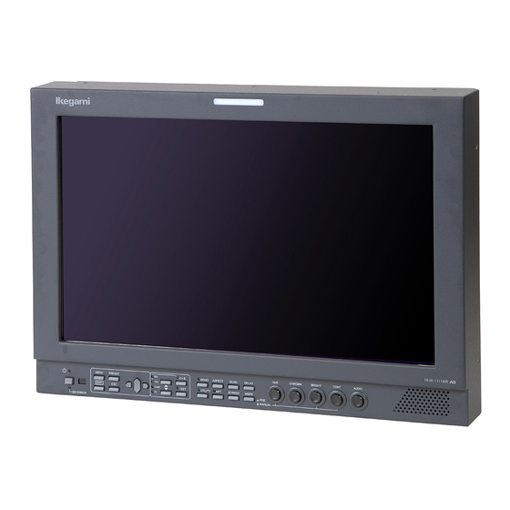
HLM-2450WB FULL HD Multi-Format LCD Color Monitor 1.Outline 1-1.Outline (3) Diverse input sources This 24-inch type HDTV/SDTV multi-format color The monitor is standard equipped with two SDI monitor employs a full high-definition liquid crystal signal (compatible with both HD/SD 4:2:2) inputs and two analog composite signal inputs. - Page 12 The monitor can also get the 1%-stepwise safety displayed. marker displayed in the range of 80-99% with respect to the line marker area. (12) 2-picture split display function The safety markers over the effective screen can be A previously captured still image and a currently equally preset 1% by 1% in the range of 80-99%.
-
Page 13: Names Of Parts And Their Functions
2.Names of parts and their Functions 2-1.Front Controller Parts ○ ○ ○ ○ CHROMA BRIGHT CONT AUDIO MENU PRESET CH B MONO ASPECT SCAN TEST SCREEN MARK OPT. PRE. MANUAL SDI ERROR ○ ○ ○ ○ ○ ○ ○ ○ ○... - Page 14 ⑩ F1 switch ⑮ APT switch ・ Press this switch to select an item preset on the ・Press this switch to select the aperture. menu. ・Set a correction amount on PRESET MENU. ・ For presettable items, refer to "4-4. Description on ※...
-
Page 15: Rear Panel (Left Bottom)
If the indicator lights up, check the details on a USB terminal waveform monitor or the like. ・ Connect a USB memory, and the monitor’s data ・By turning this setting to MENU2, the monitor can be saved on the USB memory or the data on can be set so that the front SDI ERROR LED will the USB memory can be downloaded on another not be forcefully turned ON even when an SDI... -
Page 16: Rear Panel ( Video Inputs/Outputs)
2-3.Rear panel (video inputs/outputs) REMOTE PARALLEL ⑤ ① ⑨ TEST ⑥ HD/4:2:2 CH A SERIAL ② CH B RS-485 ⑦ MONITOR ③ CH A AUDIO ⑧ ④ CH B ① DVI-D signal input ⑥ SERIAL REMOTE signal input ・ This connector is used to connect the DVI-D ・... -
Page 17: Option (Cm-175 Input/Output)
2-4.Option (CM-175 input/output) ① ② External sync signal input ・ Feed an external sync signal here when externally COMPONENT synchronizing component signals.。 ・ If not adopting the loop through connection method, connect the terminating plug. Pb/B ・ To switch to EXT SYNC, make the setting on MENU1. -
Page 18: Option (Ea-240D Output)
2-6.Option (EA-240D output) ① Embedded AES/EBU output ① AUDIO OUT (AES/EBU) ・ Eight embedded audio channels multiplexed in SDI CH1-2 are outputted as digital audio signals in AES/EBU format. CH3-4 ・ Consumer format (SPDIF) is not supported. ・ Use a converter when connecting the equipment of CH5-6 110Ω... -
Page 19: Markers
3.Markers 3-1.Types of Markers In the 16:9 aspect ratio display mode (HDTV/SDTV) In the 4:3 aspect ratio display mode (SDTV) (1) Safety marker (9) Safety marker Active screen area Active screen area (4:3) 100% area 100% area Variable from 80% to 99% Variable from 80% to 99% (1% increments) (1% increments) -
Page 20: Menu Functions
4.MENU Functions 4-1.List of MENU All functions can be executed in the MENU screen. MENU1 Setting the VBS input MENU 1.VBS FORMAT (FORMAT) Setting the decoder Y/C separation 2.→Y/C SEP. Setting the NTSC setup level 3.→NTSC SETUP LVL Setting the VIDEO line signal of DVI inputs 4.DVI FORMAT Setting the YPbPr/RGB signal format of DVI inputs 5.→YPbPr/RGB... - Page 21 Setting the 5.1 channel surround downmix 8.DOWNMIX SETTING Setting the downmix formats (ARIB/ISO IEC) 9.→FORMAT Setting the Ls/Rs level (-3dB/-6dB/-9dB/OFF) 10.→Ls/Rs LEVEL Setting the embedded audio channel assignment of speaker (Lm) 11.→INPUT OF Lm Setting the embedded audio channel assignment of speaker (Rm) 12.→INPUT OF Rm Setting the embedded audio channel assignment of speaker (C) 13.→INPUT OF C...
-
Page 22: Flow Of Menu Operations
4-2.Flow of MENU Operations MENU can be switched as follows using the MENU switch. <Normal Screen> MENU Set the format of each Sub menu enable Main menu enabled input signal. MENU1(FORMAT):1080i MENU1(FORMAT):1080i FORMAT FORMAT MODE MODE 1.VBS FORMAT 1.VBS FORMAT 2.→Y/C SEP. 2DYCS TC/WFM/VSC... - Page 23 ▼ ▲ MENU5(VIDEO) Set the image-related items. FORMAT 1.CHROMA GAIN UP OFF MODE 2.IP MODE FRAME TC/WFM/VSC 3.H POSITION 0 CAPTURE 4.V POSITION 0 VIDEO 5.CONTRAST RANGE NORMAL AUDIO MARKER P.REMOTE PC SETUP RESET INFO. USB MENU ▲ ▼ MENU6(AUDIO) FORMAT Set the audio-related items. 1.LINE/SP CH. CH1/2 MODE ...
- Page 24 ▼ ▲ MENU9(PC SETUP) FORMAT Set the PC input-related items. 1.DVI SETUP MODE TC/WFM/VSC 2.→EXPANSION NORMAL CAPTURE 3.COMP SETUP EXECUTE 4.→INPUT SELECT VIDEO 5.→EXPANSION NORMAL AUDIO MARKER 6.→XGA/WXGA XGA 7.AUTO ADJUST EXECUTE P.REMOTE 8.→H POSITION 0 PC SETUP RESET 9.→V POSITION 0 10.→CLOCK 0 INFO. 11.→PHASE 0 USB MENU...
-
Page 25: Description Of Menu 1 Functions
4-3.Description of MENU 1 Functions *Note the following description on the menu. ・The vertical frequency “/60” includes both 60 Hz and 59.94 Hz (60/1.001). ・The vertical frequency “/48” includes both 24 psF and 23.98 psF (24/1.001) in SF mode. ・The vertical frequency “/24” includes both 24 Hz and 23.98 Hz (24/1.001). MENU1(FORMAT):1080i... -
Page 26: Description Of Menu 2 Functions
4-4.Description of MENU 2 Functions MENU2(MODE) 1.FUNCTION1 MODE WFM ON ① Setting the function assignment of F 1 switch 2.FUNCTION2 MODE VITC ON ② Setting the function assignment of F 2 switch 3.REMOTE NO. 01 ③ Setting the serial remote control ID number 4.CHANGE ASPECT AUTO ④... - Page 27 ⑦ Setting the tally lamp indication ⑨ Setting the SDI channel switching lock ON/OFF ・ The lock is set to "ON" to prevent SDI signal ・Set any of the following display modes of the tally channel switching. lamps located at the top of the front of the ・...
-
Page 28: Description Of Menu 3 Functions
4-5.Description of MENU 3 Functions MENU3(VITC/WFM/VSC) ① Setting the SDI VITC display ON/OFF 1.SDI VITC OFF ② Setting the SDI VITC display brightness 2.→DIMMER MID ③ Setting the SDI VITC display Size 3.→SIZE NORMAL ④ Setting the waveform display ON/OFF 4.WFM DISPLAY OFF ... - Page 29 ⑨ Setting the VECTOR SCOPE display ON/OFF ⑬ Setting the VECTOR SCOPE display position ・Used to turn on or off the VECTOR SCOPE ・Used to set the waveform display to any of the display. RIGHT, CENTER and LEFT positions. ・This function can be assigned with the F1 F2 ・When used commonly with WFM, the VECTOR switch on the front panel.
-
Page 30: Description Of Menu 4 Functions
4-6.Description of MENU 4 Functions MENU4(SCREEN CAPTURE) ① Executing the 2-picture split mode 1.SCR CAPTURE EXECUTE 2.→AREA FULL ② Setting of 2-picture split display area SET→ EXIT→ E S C ENT ① Executing the 2-picture split mode ② Setting of 2-picture split display area ・Used to execute this mode to take in the still ・Used to set the display area in the 2-picture split image of an input signal and compare it with... -
Page 31: Description Of Menu 5 Functions
4-7.Description of MENU 5 Functions MENU5(VIDEO) ① Setting the chroma gain-up ON/OFF 1.CHROMA GAIN UP OFF ② Setting the IP conversion mode 2.IP MODE FRAME ③ Adjusting the horizontal screen position 3.H POSITION 0 ④ Adjusting the vertical screen position 4.V POSITION 0 5.CONTRAST RANGE NORMAL ⑤... -
Page 32: Description Of Menu 6 Functions
4-8.Description of MENU 6 Functions MENU6(AUDIO) 1.LINE/SP CH. CH1/2 ① Setting the channel of embedded audio output 2.SP INPUT SEL. AUTO ② Setting the audio output signals 3.LEVEL INDICATOR OFF ③ Setting the audio level meter display ON /OFF 4.→MODE 1(1357-2468) ④ Setting the mode display of audio level meter 5.→CHANNEL... - Page 33 ⑥ Setting the brightness of audio level meter ⑫ Setting the embedded audio channel assignment ・Set the brightness of the audio level meter. of speaker (Rm) ・The level meter image transmissive mode or ・Set the channel of embedded audio, which the nontransmissive mode can be set.
-
Page 34: Description Of Menu 7 Functions
4-9.Description of MENU 7 Functions MENU7(MARKER) 1.MARKER( 16:9) SAFETY ① Setting the type of marker (at 16:9 aspect ratio) 2.→SAFETY AREA 80% ② Setting the safety marker area (at 16:9 aspect ratio) 3.→ASPECT 4:3 ③ Setting the type of aspect marker (at 16:9 aspect ratio) 4.→AREA IN ASPECT... - Page 35 ④ Setting the safety marker area in aspect marker ⑦ Setting the type of aspect marker (at 4:3 aspect area (at 16:9) ratio) ・Used to set the safety marker in the aspect ・Used to select the type of aspect marker from marker (4:3, 13:9, 14:9 and 15:9) area in the “13:9, 14:9, 15:9 and 16:9”...
-
Page 36: Description Of Menu 7 (User Marker) Functions And Making Settings
⑬ Setting the user marker display ON/OFF ⑭ Executing the user marker for the drawing ・Used to turn on and off the user marker display. setting ・This function can be assigned with the F1 F2 menu switch on the front panel. ・Press ENT with EXECUTE, and the user marker ・Default setting is OFF. - Page 37 ④ User marker coordinates ・In the “DATA (X Y)” column, the coordinates for ●Marker lines and coordinate values S:START POINT and E:END POINT of the There are 2 line widths for the user markers. currently set user markers are displayed. However, the coordinate for the start point and without such settings, the “—”...
-
Page 38: Set User
How to preset new user markers X axis ⑤ Setting the start point ① Setting the marker display ON/OFF With nothing registered, the START POINT ( X:0960 Y:0540) MENU7(MARKER) initial X-Y END POINT ( X:0960 Y:0540) 1.MARKER( 16:9) SAFETY coordinate is 2.→SAFETY AREA 80% displayed, and 3.→ASPECT 4:3... - Page 39 How to modify the user markers X axis ⑤ Setting a new start point ① Setting the marker display ON/OFF The start-point START POINT ( X:0300 Y:0250) X-Y coordinate MENU7(MARKER) END POINT ( X:1200 Y:0500) starts blinking. 1.MARKER( 16:9) SAFETY 2.→SAFETY AREA 80% 3.→ASPECT 4:3 The magenta- 4.→AREA IN ASPECT...
-
Page 40: Description Of Menu 8 Functions
4-11.Description of MENU 8 Functions MENU8(PARALLEL REMOTE) 1.PIN FUNCTION DEFAULT ① Setting the functions of parallel remote pins P2:CH-B P9 :EXT SYNC P3:(blank) P10:16:9 P4:G-TALLY P11:DVI P5:COMP. P12:MARKER ② Setting the user pin functions P6:(blank) P13:SHADOW P7:MONO P14:R-TALLY P8:RGB P15:SDI (P1:GND) SET→ EXIT→ E S C ENT... -
Page 41: Description Of Menu 9 Functions
4-12.Description of MENU 9 Functions MENU9(PC SETUP) 1.DVI SETUP ① Setting the display mode with DVI input (PC format) 2.→EXPANSION NORMAL 3.COMP SETUP ② Switching between analog PC and COMPONENT input signals (Settings only for the CM-175) 4.→INPUT SELECT VIDEO ③ Setting the display mode with analog PC input (Settings only for the CM-175) 5.→EXPANSION... -
Page 42: Description Of Menu 10 Functions
⑤ Executing the automatic adjustment of PC input ⑦ Adjusting the vertical onscreen position with PC input (Only for the DVI(PC) and CM-175) (Only for the DVI(PC) and CM-175) ・Used to adjust the vertical onscreen position. ・Used to automatically adjust the phase, clock and horizontal/vertical onscreen position in Items ⑥... -
Page 43: Description Of Menu 11 Functions
4-14.Description of MENU 11 Functions MENU11(INFORMATION) 1.MPU VERSION 01.00 ① Displaying the MPU version 2.FPGA VERSION 10 ② Displaying the FPGA version 3.WORKING TIME 50H ③ Displaying the working time 4.OPTION MODULE → NO OPTION ④ Displaying the optional module mounted SET→ EXIT→ ENT E S C ・The following message appears when no ①... - Page 44 MENU8. ・The “¥Ikegami Monitor¥menu_ ・Data capacity: Approx. 2 Kbyte sw_hlm2450b_001.txt” file can be read. ・Files common for the ・This file is specific for the HLM-2450WB. HLM-1750WR,HLM-2450W/WA and The data of the HLM-1750WR,2450W/WA, HLM-3250W. HLM-3250W and other models cannot be downloaded..
- Page 45 c) □PRESET ◆Precautions on downloading ・With a USB memory connected, do not turn on ・Tick this check box to download the items and off the monitor power. Do not draw out the preset in PRESET MENU and the D65, D93 inserted USB memory while the downloading is and FILE1 thru -8 data.
-
Page 46: In Case Of Trouble
How to write from monitor to USB memory ◆Precaution MENU12(USB MEMORY) Enter the data and time of a <MONITOR → USB MEMORY> Do not draw out the inserted USB memory 1.SETTING OF DATE & TIME file to be written on a USB 2.→DATE Y/M/D 10/01/01 until the writing has been completed. If memory. -
Page 47: Monitor Front
How to download from USB memory to monitor MENU12(USB MEMORY) Tick the check box (ES) <MONITOR → USB MEMORY> ◆Precaution 1.SETTING OF DATE & TIME (□) for items to be 2.→DATE Y/M/D 10/01/01 Do not draw out the inserted USB memory downloaded from a USB 3.→TIME H:M 00:00 4.WRITE TO MEM EXECUTE until the writing has been completed. -
Page 48: Preset Menu Function
5.Preset Menu Function 5-1.List of preset menu ・To execute the preset menu, press PRESET. * Turn off the menu screen. (PRESET MENU) ① Selection of file ① ファイル選択 1.SELECT FILE D 65 ② Change of preset data ② プリセットデータの変更 2.CHANGE DATA ③ プリセットデータの一覧表示 3.DISPLAY STATUS ③... -
Page 49: Change Of Preset Data
② Change of preset data Change of PRESET data (CHANGE DATA):D 65 (a) 選択しているファイル (a) File being selected (CHANGE DATA):FILE 1 (b) HUE data 1.HUE 0 (b) HUE データ (c) CHROMA data 2.CHROMA 0 (c) CHROMA データ 1.HUE 0 (d) BRIGHTNESS データ 3.BRIGHT... -
Page 50: Display Of Preset Data List
② and enter a four-digit password here. ⑤ Setting of file change operation at the time of * If you forget the registered password, contact channel change ・Set the association of channel change with file Ikegami’s service office. They have change. - Page 51 Chaging the lock mode Select a character (LOCK FILE/DATA) with the cross switch, and enter a STATUS:UNLOCK 4-character -ENTER PASSWORD- password. ABCDEFGHIJKLMNOPQRSTUVWXYZ 123456789 PASSWORD **** SET→ EXIT → E S C ENT With the 4- (LOCK FILE/DATA) character password entered, the STATUS:UNLOCK lock/unlock mode -ENTER PASSWORD- status appears.
-
Page 52: Mouse Menu Function
6.Mouse menu function 6-1.Basic procedure of the mouse menu Basic behavior of the mouse The USB mouse requires the following 5 functions. Remote control is enabled using a 2.4GHz wireless mouse. ①Double click The mouse basically behaves in the ④Center click ・The mouse menu is display same way as the switches on the front ・The mouse menu is... -
Page 53: Basic Procedures On The Menu And Preset Menu Screens
6-2.Basic procedures on the MENU and PRESET MENU screens ① Basic mouse behavior on the MENU screen ③ Basic mouse behavior on the CHANGE PRESET screen (CHANGE DATA):FILE 1 Select Select 1.HUE 0.0 2.CHROMA 100 3.BRIGHT 0.0 4.CONT 100.0 MENU1(FORMAT):1080i FORMAT 5.R.BKG... -
Page 54: Specifications
7.Specifications d) Transmission speed 7-1.General specifications (1) Supply voltage HD-SDI :1.485Gb/s AC input SD-SDI :270Mb/s ・100V~120V±10% 50/60Hz e) Quantization bit rate ・200V~240V±10% 50/60Hz 10 bits f) Input/output impedance (2) Power consumption 75Ω g) Transmission distance AC100-120V : 1.1A Over 100m (5CFB, 1.485Gb/s) AC200-240V : 0.6A Max. - Page 55 (6) DVI-D and Analog PC signal 0.714Vp-p (NTSC)/0.7Vp-p (PAL), Positive polarity (Analog when the optional CM-175 is mounted) *DVI-D supported as standard d) Input impedance a) Input terminal High impedance bridge connection or 75Ω ANALOG: HD D-SUB 15-pin (female) 1 line termination (when optional...
-
Page 56: Module
(8) Embedded analog audio output e) Display segment (when the optional EA-240A or D3G-240A 26 segments (including -∞) are mounted) f) Segment point * Analog audio level 0dBs 0.775Vrms -∞、-60、-54、-48、-44、-40、-38、-36、-34、-32、 a) Output terminal: -12、 -30、-28、-26、-24、-22、-20、-18、-16、-14、 XLR-5-32 type (XLR type 5-pin male) -10、-8、-6、-4、-2、0dB →Refer to "Data 2 Embedded analog g) Display color... -
Page 57: Functions
(4) Screen brightness (brightness ・14:9 aspect marker (4:3/16:9) performance of LCD unit) ・13:9 aspect marker (4:3/16:9) 400 cd/m (at full white input) ・4:3 aspect marker (16:9) ・1.85:1 aspect marker (16:9) (5) Drive system ・2.35:1 aspect marker (16:9) a-Si TFT active matrix, line sequential ・... -
Page 58: Applicable Standards
10.Options ・SHADOW60 ON/OFF (★) Any one of the following optional modules can be * For the pin function, refer to "Data 3 Parallel mounted. Each module is of plug-in type for easy Remote Pin Function". replacement. * In addition to default setting, user setting is possible. -
Page 59: Hlm-2450Wb
(7) RCT-30A * The specifications and appearance of this “Infrared remote controller” product are subject to change for product Just this unit can control most of the monitor improvements without notice. functions. Up to 99 monitors can be controlled individually. * Black spots and luminescent spots may occur in 0.01% or less of the effective pixels of this (8) STD-240T (made-to-order) -
Page 60: External View
11.External View - 50 -... -
Page 61: (Ea-240A / D3G-240A)
◆RS-2450T Rack Mount ① External View ② Rack set-up drawing PARTS NAME PARTS No. Q’ty 1001 MOUNT BKT 1 M4-925306-000 1002 MOUNT BKT 2 M3-925305-000 1003 MOUNT BKT 3 M3-925308-000 2001 SCREW MCB4-6FB 2002 SCREW MCB4-6FB 2003 SCREW MCB4-6FB 2004 SCREW MCB4-8FB 2005... -
Page 62: Data 1 Pc Input Signal Compatible Format
Data 1 PC Input Signal Compatible Format Horizontal frequency Vertical frequency Clock frequency Input signal (kHz) (Hz) (MHz) VGA (640×480) 31.48 59.95 25.18 37.86 72.81 31.50 37.50 75.00 31.50 43.27 85.01 36.00 SVGA (800×600) 35.16 56.25 36.00 37.88 60.32 40.00 48.08 72.19 50.00... -
Page 63: Data 3 Parallel Remote Pin Function
Data 3 Parallel Remote Pin Function Connector Face View on Rear Panel Wiring of Remote Connector (by default) CH-B on G TALLY on COMP. on MONO on RGB on EXT-SYNC on <Connector on system side> 16:9 on D-Sub 15-pin (male) mini-type * Connector DVI on CD0115PA100:... - Page 64 ■ Additional user-set functions Pin No. Function External Assignment for Function User setting SHADOW0 on Connect to Pin 1 for running with the shadow level 0% (black). * Priority is given to this pin function if any other shadow setting pin is pressed at once. User setting SHADOW20 on Connect to Pin 1 for running with the shadow level 20%.
-
Page 65: Data 4 Control With Remote Controller
Data 4 Control with Remote Controller Serial remote Wireless remote Control item Remarks SRC-301A/Z RCT-20A/30A ■Switch functions - ○(※1) VIDEO SELECT ○ - VIDEO A (VBS) ○ - VIDEO B (VBS) ○ - RGB/YPbPr ○ - SDI A ○ - SDI B ○... -
Page 67: Lcd Color Monitor
© Mar. 2011 by Utsunomiya Factory of Ikegami Tsushinki Co., Ltd. All right reserved. Reproduction or duplication, without permission of Ikegami Tsushinki Co., Ltd. of edition or contents in whole in part, any manner, is prohibited. Specifications and design are subject to change without notice. - Page 68 Ikegami Tsushinki Co., Ltd. 5-6-16, Ikegami, Ohta-ku, Tokyo, Japan 146-8567 Phone:(03)5700-1111 Fax:(03)5700-1137 Ikegami Electronics (U.S.A.), Inc. 37 Brook Avenue, Maywood, New Jersey 07607 Phone:(201)368-9171, Fax:(201)569-1626 Ikegami Electronics (Europe) GmbH Ikegami Strasse 1, D-41460 Neuss, Germany Phone:(02131)123-0, Fax:(02131)102820 Property of PRINTED IN JAPAN...
Need help?
Do you have a question about the HLM-2450WB and is the answer not in the manual?
Questions and answers