Table of Contents
Advertisement
Quick Links
Advertisement
Table of Contents

Related Manuals for Ikegami HLM-905WR


Summary of Contents for Ikegami HLM-905WR
- Page 1 MODEL HLM-905WR MULTI FORMAT LCD COLOR MONITOR OPERATION MANUAL...
- Page 3 The “CE” mark means the products as mentioned below will meet the intent of the following Directives and Standards. Inrush current according to EN55103-1 Annex B is as follows. HLM-905WR : 0.117A r.m.s. (the average half-cycle r.m.s. inrush current, on initial switch-on.) : 0.112A r.m.s. (the average half-cycle r.m.s. inrush current after a supply interruption of 5 s.)
-
Page 4: Important Safety Instructions
IMPORTANT SAFETY INSTRUCTIONS 5) For added protection for this television equipment 1. General during a lightning storm, or when it is left 1) Read all instructions provided. unattended and unused for long periods of time, 2) Save these instructions for future use. unplug it from the wall outlet. - Page 5 5) If an image of extremely high brightness is 4) For repair service, contact Ikegami’s authorized displayed on the screen for a long time, the panel sales representative or Ikegami service desk may get burned in.
-
Page 6: Precautions For Operations
In voltage range marked on its back. such cases, contact the Ikegami service desk. 4) If cabinet or screen is dirty, wipe with soft cloth. 9) Should this unit fail within one year after delivery,... -
Page 7: Precautions Upon Use
Precautions Upon Use In order to use the monitor safely, read through this 7. Do not display the same pattern for a long time. manual and pay attention to the following points in Note that residual image may be generated if the same particular. - Page 8 If the message "FAN ERROR!" is displayed, contact your dealer or Ikegami service desk. Warranty If the product should fail within one year from the date of delivery in spite of the proper use, the manufacturer will repair the product free of charge.
-
Page 9: Table Of Contents
CONTENTS IMPORTANT SAFETY INSTRUCTIONS PRECAUTIONS FOR OPERATIONS Cautions for Rack-Mount. Precautions Upon Use For the first-time use after purchase 1. Outline................ 1 5-2- Operation of Auto Setup..... 53 1-1. Outline............. 1 5-2- Setting the backlight brightness 1-2. Features ............1 level............. -
Page 11: Outline
HLM-905WR Multi-Format LCD Color Monitor 1 Outline 1-1 Outline (4) Remote control functions The monitor can be remote-controlled with the This 9-inch type HDTV/SDTV multi-format use of three remote control functions. Depending color monitor employs a high-definition liquid on the place of installation and type of operation, crystal panel for reduction in thickness, weight the parallel, serial mode can be used. - Page 12 (7) Shadow function (12) Dot-by-dot display function The shadow function is to shade the area other All the picture elements of an input signal are than a 4:3 (16:9 mode), 13:9, 14:9, 15:9 or 16:9 (4:3 displayed 1:1 according to the pixels of the LCD mode) marker area on images.
- Page 13 And it is also able to be used as the measuring instrument for measuring color temperature (color point of x, y) and contrast. * HLM-905WR supports in more than ASP-100 Rev1. (18) IMD/UMD display by TSL protocol This is a function to control the IMD/UMD display in a centralized manner by using “TSL...
-
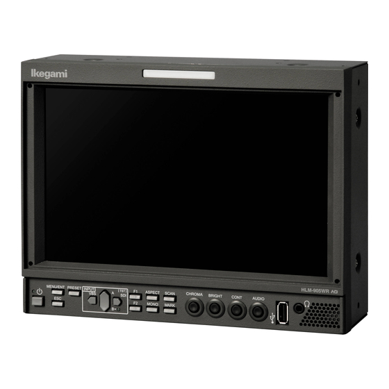
Page 14: Names Of Parts And Their Functions
2 Names of parts and their Functions 2-1 Front Controller Parts POWER switch VBS switch/ (LEFT) switch This switch is used to turn ON/OFF the monitor. To select the VBS input, this switch is pressed * This switch will not turn ON/OFF the AC power with the menu and preset menu not displayed. - Page 15 CH-B LED MONO switch This LED is lit up when CH-B is selected in the This switch is pressed to make a color signal case of the SDI input. monochrome. * When the internal test signal is displayed, this * When analog component RGB is input, this func- LED is not lit up at any time.
- Page 16 21 Stereo headphones output (stereo mini-jack type) Analog audio signals, embedded audio signals and downmix audio signals are fed out of this termi- nal. The analog and embedded inputs can be selected on MENU6. Very low sound may be audible even when the volume is at minimum position.
-
Page 17: Rear Panel (Left)
2-2 Rear panel (left) BB-904V (option) BB-904A (option) AC power supply input connector BB-904A (option) The accompanying AC cable is connected to this Insert the provided ANTON BAUER battery (DI- connector to supply AC power. ONIC 90) here to supply battery power. Locking hardware Handle This hardware is used to lock the AC plug to... -
Page 18: Rear Panel (Video Inputs/Outputs)
2-3 Rear panel (video inputs/outputs) SDI A/B signal input PARALLEL REMOTE signal input 3G-SDI, HD-SDI or SD-SDI (4:2:2) signals are Connect the accompanying remote connector here. input through this connector. For details of pin connections, refer to "D D ata 3: The format of an input signal is automatically Parallel Remote Pin Function"... -
Page 19: Markers
3 Markers 3-1 Types of Markers In the 16:9 aspect ratio display mode (HDTV/SDTV) In the 4:3 aspect ratio display mode (SDTV) (1) Safety marker (9) Safety marker Active screen area Active screen area (4:3) 100% area 100% area Variable from 80% to 99% Variable from 80% to 99% (1% increments) (1% increments) -
Page 20: Menu Functions
4 MENU Functions 4-1 List of MENU All functions can be executed in the MENU screen. MENU1 MENU 1.VBS FORMAT (FORMAT) 2. Y/C SEP. 3. NTSC SETUP LVL MENU2 1.FUNCTION1 MODE (MODE) 2.FUNCTION2 MODE 3.REMOTE NO. Setting the automatic/manual aspect ratio change as per 4.CHANGE ASPECT reception channel 5.CONT VR ASSIGN... - Page 21 MENU6 1.LINE/SP CH. (AUDIO) 2.LINE/SP INPUT 3.LEVEL INDICATOR 4. MODE 5. CHANNEL 6. DIMMER 7. PEAR HOLD 8. REF LEVEL 9.DOWNMIX SETTING 11. Ls/Rs LEVEL 1 . INPUT OF Lm 1 . INPUT OF Rm 1 . INPUT OF C 1 .
- Page 22 MENU12 <USB MEMORY MONITOR> (UPDATE) 1.CONTENTS TO DOWNLOAD MPU FIRMWARE FPGA 2.DOWNLOAD MENU13 1.FUNCTION Setting the UMD/IMD display mode (TSL/U.DISPLAY) (UMD/IMD) <USER DISPLAY> Setting the item for exclusive use of the U. DISPLAY function 2.USER DISPLAY Setting the USER DISPLAY on/off 3.BRIGHTNESS Seting the brightness for USER DISPLAY 4.
-
Page 23: Flow Of Menu Operations
4-2 Flow of MENU Operations MENU can be switched as follows using the MENU switch. - Page 25 To MENU1...
-
Page 26: Description Of Menu 1 Functions
4-3 Description of MENU 1 Functions Note the following description on the menu. The vertical frequency “/60” includes both 60 Hz and 59.94 Hz (60/1.001). The vertical frequency “/48” includes both 24 psF and 23.98 psF (24/1.001) in SF mode. The vertical frequency “/24”... -
Page 27: Description Of Menu 2 Functions
4-4 Description of MENU 2 Functions Setting the function assignment of F 1 switch Setting the function assignment of F 2 switch Setting the serial remote control ID number Setting the automatic/manual aspect ratio change Setting the assignment of CONT manual control Setting the tally lamp indication Setting the same-size (dot-by-dot) display ON/OFF... - Page 28 G/R G is on the left side and R on the right side, Setting the function assignment of F2 switch The function assignment is selectable in the same when facing the screen. way as that shown above by pressing the F2 switch on the front panel.
- Page 29 C/T(Screen top center displayed) DC+14.8V Battery with nominal voltage of 14.8V or 14.4V C/B(Screen bottom center displayed) DC+13.2V Battery with nominal voltage of R/T(Screen top right displayed) 13.2V R/C(Screen center right displayed) DC+12.0V Battery with nominal voltage of R/B(Screen bottom right displayed) 12.0V In the 480i/575i/720p format, the image appears Default setting is AC/Ext.
-
Page 30: Description Of Menu 3 Functions
4-5 Description of MENU 3 Functions Setting the SDI VITC display ON/OFF Setting the SDI VITC display brightness Setting the SDI VITC display Size Setting the waveform display ON/OFF Setting the waveform display brightness Setting the waveform display size Setting the waveform display position Setting the waveform display color Setting the VECTOR SCOPE display ON /OFF Setting the VECTOR SCOPE display brightness... - Page 31 Setting the VECTOR SCOPE display ON/OFF Setting the VECTOR SCOPE display position Used to turn on or off the VECTOR SCOPE dis- Used to set the waveform display to any of the play. RIGHT, CENTER and LEFT positions. This function can be assigned with the F1 F2 When used commonly with WFM, the VECTOR switch on the front panel.
-
Page 32: Description Of Menu 4 Functions
4-6 Description of MENU 4 Functions Executing the 2-picture split mode Setting of 2-picture split display area Executing the full capture mode Manual switching mode between full capture image and input signal image Automatic switching mode between full capture image and input signal image Setting up the interval of the automatic switching mode a) Current memory status Setting the file number of the full capture image... - Page 33 Manual switching mode between full capture image and input signal image This operation is possible after the full capture mode described under item has been exe- cuted. Whenever the ENT switch is pressed, the full capture image and the image of the input signal will be instantly switched over as illustrated on the diagram at left, making it possible immedi- ately to compare the images.
- Page 34 The file format that has been used is exclusive to File Capacity: 3MB~4MB per image file HLM-905WR. Downloading from UBS memory to monitor Downloading the capture image stored in the USB memory to the monitor For details of the method of downloading the...
- Page 35 How to write of full capture data from monitor to USB memory In case of trouble In normal state...
- Page 36 How to download full capture data from USB memory to monitor...
-
Page 37: Description Of Menu 5 Functions
4-7 Description of MENU 5 Functions Setting the chroma gain-up ON/OFF Setting the IP conversion mode Adjusting the horizontal screen position Adjusting the vertical screen position Setting the contrast range Setting the chroma gain-up ON/OFF Adjusting the horizontal screen position Set the gain-up ON/OFF for chroma signals. -
Page 38: Description Of Menu 6 Functions
4-8 Description of MENU 6 Functions Setting the channel of embedded audio output Setting the audio output signals Setting the audio level meter display ON /OFF Setting the mode display of audio level meter Setting the channel display of audio level meter Setting the brightness of audio level meter Setting the peak hold ON/OFF Setting the reference level (-20dBFS/-18 dBFS) - Page 39 MODE5 (1357-2468) Setting the peak hold display of audio level meter Used to turn on and off the peak hold display. Default setting is ON. Setting the reference level Set the reference level of the audio level meter. -18dBFS -20dBFS Default setting is -20dBFS Downmix setting Set the 5.1 channel surround downmix.
- Page 40 Setting the embedded audio channel assignment of speaker (Ls) Set the channel of embedded audio, which the audio for 5.1ch surround Ls speaker (left side in rear) should be assigned from. Default setting is CH5 Setting the embedded audio channel assignment of speaker (Rs) Set the channel of embedded audio, which the audio for 5.1ch surround Rs speaker (right side...
-
Page 41: Description Of Menu 7 Functions
4-9 Description of MENU 7 Functions Setting the type of marker (at 16:9 aspect ratio) Setting the safety marker area (at 16:9 aspect ratio) Setting the type of aspect marker (at 16:9 aspect ratio) Setting the safety marker area in aspect marker area (at 16:9) Setting the type of marker (at 4:3 aspect ratio) Setting the safety marker area (at 4:3 aspect ratio) Setting the type of aspect marker (at 4:3 aspect ratio) - Page 42 Default setting is SAFETY. Setting the center cross marker ON/OFF Used to turn on and off the center cross marker. Default setting is OFF. SAFETY ASPECT C.CROSS CROSS5 CROSS10 Setting the safety marker area (at 4:3 aspect ratio) Setting the marker display level Used to set the safety marker area in the 80%- Used to set the marker display level.
-
Page 43: Description Of Menu7 (User Marker) Functions And Making Settings
4-10 Description of MENU7 (USER MARKER) Functions and Making Settings PAGE PAGE DATA(X Y) ON/OFF How to turn from PAGE1 to PAGE2 When the blinking cursor is at MK1, use the switch to go to PAGE2. With the blinking cursor at MK5, use switch to go to PAGE2. - Page 44 Marker lines and coordinate values User marker coordinates In the DATA (X Y) column, the coordinates for There are 2 line widths for the user markers. S START POINT and E END POINT of the However, the coordinate for the start point and currently set user markers are displayed.
-
Page 47: Description Of Menu 8 Functions
4-11 Description of MENU 8 Functions Setting the functions of parallel remote pins Setting the user pin functions SHADOW0 SHADOW20 Setting the functions of parallel remote pins Select the pre-assigned pin functions of parallel SHADOW40 SHADOW60 func- remote control or the individual user-set func- tions tions. -
Page 48: Description Of Menu 9 Functions
4-12 Description of MENU 9 Functions Executing the initialization of set data Selecting the preset files to be initialized Executing the initialization of set data Selecting the preset files to be initialized Perform this setting to restore the default set- When PRESET is selected in... -
Page 49: Description Of Menu 11 Functions
The password lock and the password memory are created in the following 3 text files in itself are not saved, however. the Ikegami Monitor folder that is automatically Data capacity: Approx. 3 Kbyte prepared. This file is specific for the HLM-905WR. - Page 50 Do not mod- As this is a file exclusive to the HLM-905WR, it ify the data in a file, or else the order of the is not possible to download any data saved by data may be altered, disabling writing of the data.
- Page 51 Error messages during writing or downloading Precautions on downloading With a USB memory connected to the monitor, do ILLEGAL DATA: Checksum error not turn ON/OFF the monitor or disconnect the FILE IS NOT FOUND: File is not found. inserted USB memory while downloading is go- ERROR01: A file system error is detected ing on, or else the USB memory may possibly be...
- Page 52 How to write from monitor to USB memory In case of trouble In normal state - 42 -...
- Page 53 How to download from USB memory to monitor In case of trouble In normal state - 43 -...
-
Page 54: Description Of Menu 12 Functions
It is possible to download both items simulta- neously. The file name of the FPGA data exclu- MPU FIRMWARE sive to the HLM-905WR contains 3 When updating the MPU firmware, tick the check numeric characters following letter “v” box here. - Page 55 How to update MPU from USB memory In case of trouble In normal state - 45 -...
- Page 56 How to update FPGA from USB memory In case of trouble In normal state In case of trouble - 46 -...
-
Page 57: Description Of Menu 13 Functions
4-16 Description of MENU 13 Functions Setting the UMD/IMD display mode (TSL/U.DISPLAY) Setting the USER DISPLAY no /off Setting the brightness for USER DISPLAY Setting the indication text contents for USER DISPLAY Setting the monitor ID code for TSL control Setting the device turning on TALLY for TSL control Setting the LH TALLY color for TSL control Setting the RH TALLY color for TSL control... - Page 58 <If DISPLAY is specified, TALLY will be displayed on Setting the color of characters to be displayed the screen> (Common setting item) If the character size is NORMAL: Select the color of the characters to be displayed from 7 colors including WHITE, YELLOW, CYAN, GREEN, MAGENTA, and BLUE.
- Page 59 UMD/IMD Indication Table TEXT SIZE NORMAL TEXT SIZE NORMAL TEXT POSITION BOTTOM TEXT POSITION DISPLAY POSITION CENTER DISPLAY POSITION CENTER TEXT SIZE SMALL TEXT SIZE SMALL TEXT POSITION BOTTOM TEXT POSITION DISPLAY POSITION CENTER DISPLAY POSITION CENTER TEXT SIZE NORMAL TEXT SIZE NORMAL TEXT POSITION...
-
Page 60: Preset Menu Function
5 Preset Menu Function 5-1 List of preset menu To execute the preset menu, press PRESET. * Turn off the menu screen. Selection of file Change of preset data Display of preset data list Copying of file data Setting of file change at the time of channel change Setting of data protection password Auto white balance Setting the backlight brightness level... -
Page 61: Change Of Preset Data
Change of preset data (a) File being selected (b) HUE data (c) CHROMA data (d) BRIGHTNESS data (e) CONTRAST data (f) R. BACKGROUND data (g) G. BACKGROUND data (h) B. BACKGROUND (i) R. GAIN data (j) G. GAIN data (k) B. GAIN data (l) Aperture level (m) Aperture frequency Change the data of a file selected in "... -
Page 62: Display Of Preset Data List
Set the association of channel change with file * If you forget the registered password, contact change. Ikegami’s service office. They have a pass- AUTO: Files memorized each word for releasing the lock. -
Page 63: Operation Of Auto Setup
Please refer an operation manual for ASP-100 regarding the de- tail. * HLM-905WR supports in more than ASP-100 Rev1. Setting the backlight brightness level When the backlight brightness level is raised, the black level is also slightly raised. -
Page 64: Mouse Menu Function
6. Mouse menu function 6-1 Basic procedure of the mouse menu The USB mouse requires the following 5 functions. Remote control is enabled using a 2.4GHz wireless mouse. Double click The mouse basically behaves in the Center click The mouse menu is display same way as the switches on the front The mouse menu is panel bottom. -
Page 65: Basic Procedures On The Menu And Preset Menu Screens
6-2 Basic procedures on the MENU and PRESET MENU screens Basic mouse behavior on the MENU screen Basic mouse behavior on the CHANGE PRE- SET screen Left-click the mouse to go to the right of the MENU screen and select an item. Right-click it to return to the left-hand items. -
Page 66: Specifications
7. Specifications c) Input level 7-1 General specifications (1) Supply voltage Rating: 800mVp-p±10% AC input d) Transmission speed 100V 120V 10% 50 60Hz 3G-SDI: 2.970Gb/s 200V 240V 10% 50 60Hz HD-SDI: 1.485Gb/s DC input SD-SDI: 270Mb/s DC+12V e) Quantization bit rate 10 bits (2) Power consumption f) Input/output impedance... -
Page 67: Specifications For Liquid Crystal Display (Lcd)
(4) Embedded audio level meter (supported as (7) Headphones output (supported as standard) standard) a) Output terminal a) Display method 3.5 Stereo mini jack type Superimposition on screen b) Output b) Display channel 85 mW/ch (RL: 32 , distortion factor: 1%) 8 ch c) Input signal source c) Display position... -
Page 68: Functions
(8) Contrast ratio The “safety marker in aspect” refers to 1000:1 (typ.) the safety marker with respect to the aspect marker display zone, and can be (9) Number of display colors preset 1% by 1% in the range of 80-99%. 16.78 million colors (8bits) Corresponding to each aspect marker. -
Page 69: Remote Control
a) Characters: ASCII (alphanumeric); 8. Applicable Standards Max. of 8 characters in 7 8-1 Safety standards colors UL1419 b) Display position: Top or bottom EN60950-1 (7) USB memory function 8-2 Electromagnetic interference a) Content of the memory FCC Class-A MENU setting EN55103-1 E4 User marker EN55103-2 E4... -
Page 70: Options
Designed specifically for strument for measuring color temperature (color point HLM-904/905/907WR. of x, y) and contrast.. Weight: approx. 100g Monitor+WFM(Made by Leader Electronics * HLM-905WR/907WR supports in more than Corp.: LV5330) ASP-100 Rev1. 4U-size rack mount hardware (3) DR-904 (11) WR-904C (made-to-order) “Dual rack mount hardware”... - Page 71 Specific for the HLM-904/905WR Weight: approx. 74g (21) MH-904 “Folding hood” Specific for the HLM-904/905/907WR Weight: approx. 0.58Kg (22) CC-905 “Hard carrying case” Specific for the HLM-905WR (23) SO-106 “Soft carrying case” Made by SEKAIDO. Inc. Specific for the HLM-904/905/907WR - 61 -...
-
Page 72: External View
10 External View (1) MAIN CHASSIS - 62 -... -
Page 73: Option (Std-900,Bb-904V,Pp-904)
(2) Option STD-900, BB-904V, PP-904 [UNIT:mm] (3) Option STD-900, BB-904A, PP-904 [UNIT:mm] - 63 -... -
Page 74: Option (Std-920T,Bb-904V,Pp-904)
(4) Option STD-920T, BB-904V, PP-904 [UNIT:mm] (5) Option DR-904 [UNIT: mm] - 64 -... - Page 75 (6) Option AT-900 [UNIT: mm] - 65 -...
-
Page 76: Data 1 Parallel Remote Pin Function
Data 1 Parallel Remote Pin Function Wiring of Remote Connector (by default) Connector Face View on Rear Panel CH-B on G TALLY on MONO on <Connector on system side> D-Sub 15-pin (male) mini-type 16:9 on * Connector CD0115PA100: CVILUX-made * Case MARKER on DE-C8-J9-F2-1: SHADOW on... - Page 77 Setting of two shadow levels and behavior The shadow levels can be very quickly switched each other. To do this, make the user setting to assign the par- allel-remote pin functions to “SHADOW0”, “SHADOW20”, “SHADOW40”, “SHADOW60”, etc. Typical setting procedure and behavior are shown below. Setting procedure MENU8 (Parallel Remote) MENU8 (Parallel Remote)
-
Page 78: Data 2 Control With Remote Controller
Data 2 Control with Remote Controller Serial remote Control item Remarks SRC-301A/Z Switch functions VIDEO (VBS) SDI A SDI B TEST APERTURE ON/OFF COLOR/MONO BLUE ONLY ON/OFF DELAY (H/V/PCR) only SDI 4:3/16:9 SCAN only SDTV SELECT FILE SELECT MARKER ON/OFF MENU Variable preset level functions only VBS(NTSC) -
Page 79: Lcd Color Monitor
© May. 2013 by Utsunomiya Factory of Ikegami Tsushinki Co., Ltd. All right reserved. Reproduction or duplication, without permission of Ikegami Tsushinki Co., Ltd. of edition or contents in whole in part, any manner, is prohibited. Specifications and design are subject to change without notice. - Page 80 Ikegami Tsushinki Co., Ltd. 5-6-16, Ikegami, Ohta-ku, Tokyo, 146-8567, Japan Phone: +81-(0)3-5700-4114 Fax: +81-(0)3-5748-2200 E-mail: info_e@ikegami.co.jp URL: http://www.ikegami.co.jp/en/ Ikegami Electronics (U.S.A.), Inc. 37 Brook Avenue, Maywood, New Jersey 07607, U.S.A. Phone: +1-201-368-9171 Fax: +1-201-569-1626 E-mail: engineering@ikegami.com, service@ikegami.com URL:http://www.ikegami.com Ikegami Electronics (Europe) GmbH...
Need help?
Do you have a question about the HLM-905WR and is the answer not in the manual?
Questions and answers