Table of Contents
Advertisement
Quick Links
Advertisement
Table of Contents

Subscribe to Our Youtube Channel
Related Manuals for Ikegami HLM-3250W


Summary of Contents for Ikegami HLM-3250W
- Page 1 MODEL HLM-3250W FULL HD MULTI FORMAT LCD COLOR MONITOR OPERATION MANUAL...
- Page 3 HLM-3250W: 17.4 A Directives : 93/68/EEC, 2004/108/EC, 92/31/EEC for EMC (electromagnetic compatibility) 2006/95/EC for Low voltage (Safety) Standards : HLM-3250W : EN55103-1-E4, EN55103-2-E4, EN60950-1 WARNING: TO REDUCE THE RISK OF ELECTRIC SHOCK, DO NOT EXPOSE THIS EQUIPMENT TO RAIN OR WATER.
- Page 4 IMPORTANT SAFETY INSTRUCTIONS 3) When connecting and disconnecting the 1. General power cable, be sure to hold the plug. 1) Read all instructions provided. 4) Do not allow anything to rest on the power 2) Save these instructions for future use. cord.
- Page 5 3) Upon completion of any service or repairs to this monitor, ask the service technician to perform routine safety checks to determine that the television is in safe operating condition. 4) For repair service, contact Ikegami’s authorized sales representative or Ikegami service desk directly.
- Page 6 Be sure to operate the color monitor within yourself. In such cases, contact the Ikegami the voltage range marked on its back. service desk. 4) If cabinet or screen is dirty, wipe with soft 9) Should this unit fail within one year after cloth.
-
Page 7: Precautions Upon Use
Precautions Upon Use In order to use the monitor safely, read through this manual and pay attention to the following points in particular. 1. Do not use any power supply other than the specified one (AC). 2. Do not give a shock to the monitor. Be very careful to keep the monitor from shocks because glass is used inside the LCD. - Page 8 The brightness of the backlight may be reduced in order to keep the internal temperature of the motor from rising. If the message "FAN ERROR!" is displayed, contact your dealer or Ikegami service desk. Warranty If the product should fail within one year from the date of delivery in spite of the proper use, the manufacturer will repair the product free of charge.
-
Page 9: Table Of Contents
CONTENTS IMPORTANT SAFETY INSTRUCTIONS PRECAUTIONS FOR OPERATIONS Cautions for Rack-Mount. Precautions Upon Use For the first-time use after purchase 5. Preset Menu Function ......... 37 1. Outline ............5-1. List of preset menu ......37 1-1. Outline ..........5-2. Description of preset menu .... 37 1-2. -
Page 10: Outline
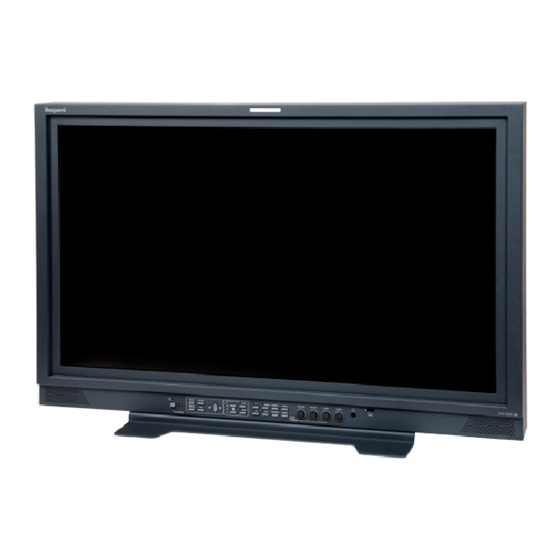
H H LM-3250W FULL HD Multi-Format LCD Color Monitor HLM-3250W FULL HD Multi-Format LCD Color Monitor (3) Diverse input sources 1. Outline The monitor is standard equipped with two SDI 1-1. Outline signal (compatible with both HD/SD 4:2:2) inputs and two analog composite signal inputs. - Page 11 (6) Built-in markers (11) Waveform monitor/Vector scope display 4:3 (16:9 mode), 13:9, 14:9, 15:9, 16:9 (4:3 mode), functions 1.85:1 (16:9 mode) and 2.35:1 (16:9 mode) line markers Waveform monitor of brightness signal can be can be displayed. displayed. The display comes in two sizes, NORMAL The monitor can also get the 1%-stepwise safety and SMALL, and its brightness in three levels.
-
Page 12: Names Of Parts And Their Functions
2. Names of parts and their Functions 2-1. Front Controller Parts CHROMA BRIGHT CONT AUDIO MENU PRESET CH B MONO ASPECT SCAN TEST SCREEN MARK OPT. PRE. MANUA L SDI ERRO R CHROMA BRIGHT CONT AUDIO MENU PRESET CH B MONO ASPECT SCAN TEST SCREEN... - Page 13 ⑩ F1 switch ⑮ APT switch Press this switch to select an item preset on the Press this switch to select the aperture. menu. Set a correction amount on PRESET MENU. For presettable items, refer to "4-4. Description ※In the PC input mode, this function is disabled. on MENU 2 Functions".
-
Page 14: Rear Panel (Left Bottom)
Infrared receiver of wireless remote control Stereo speakers When a wireless remote controller (RCT-20A/RCT- Analog audio signals or embedded audio signals 30A) is used, point it towards this receiver. are fed out of this terminal. The analog and embedded inputs can be selected on MENU. -
Page 15: Rear Panel (Video Inputs/Outputs)
2-3. Rear panel (video inputs/outputs) REMOTE PARALLEL ⑤ ① ⑨ TEST ⑥ HD/4:2:2 CH A SERIAL ② CH B RS-485 ⑦ MONITOR ③ CH A AUDIO ⑧ ④ CH B ① DVI-D signal input ⑥ SERIAL REMOTE signal input This connector is used to connect the DVI-D signal Connect the BNC cable from the SRC-301A/Z serial from the PC. -
Page 16: Option (Cm-240 Input/Output)
② External sync signal input 2-4. Option (CM-240 input/output) Feed an external sync signal here when externally ① synchronizing component signals. If not adopting the loop through connection method, connect the terminating plug. COMPONENT To switch to EXT SYNC, make the setting on Y/ G MENU1. -
Page 17: Option (Ea-240D Output)
2-6. Option (EA-240D output) ① Embedded AES/EBU output ① AUDIO OUT (AES/EBU) Eight embedded audio channels multiplexed in SDI CH1-2 are outputted as digital audio signals in AES/EBU format. CH3-4 Consumer format (SPDIF) is not supported. Use a converter when connecting the equipment CH5-6 of 110 impedance. -
Page 18: Markers
3. Markers 3-1. Types of Markers In the 16:9 aspect ratio display mode (HDTV/SDTV) In the 4:3 aspect ratio display mode (SDTV) (1) Safety marker (9) Safety marker Active screen area Active screen area (4:3) 100% area 100% area Variable from 80% to 99% Variable from 80% to 99% (1% increments) (1% increments) -
Page 19: Menu Functions
4. MENU Functions 4-1. List of MENU All functions can be executed in the MENU screen. MENU1 MENU 1.VBS FORMAT Setting the VBS input (FORMAT) 2.→ Y /C SEP. Setting the decoder Y/C separation 3.→ N TSC SETUP LVL Setting the NTSC setup level 4.DVI FORMAT Setting the VIDEO line signal of DVI inputs 5.→ ... - Page 20 MENU8 1.MARKER (16:9) Setting the type of marker displayed at 16:9 aspect ratio (1/2) (MARKER) 2.→ S AFETY AREA Setting the 16:9 safety marker area (80-99% (1% increments)) 3.→ A SPECT Setting the type of aspect marker at 16:9 display Setting the safety marker (80-99% (1% increments)) 4.→ ...
-
Page 21: Flow Of Menu Operations
4-2. Flow of MENU Operations MENU can be switched as follows using the MENU switch. <Normal Screen> M E N U Sub menu enabled Main menu enabled Set the format of each input signal. MEN U 1( F OR M AT ) :1 0 80 i ME ... - Page 22 ▼ ▲ M E NU 5 ( S C R E E N CA P T U R E ) 1. F M T Set the 2-picture split mode items. 2. M O D E 1 . S CR C A P T UR E E ...
- Page 23 ▼ ▲ MEN U 9(PARALLEL REMOTE) 1.F M T Set the parallel remote-related items. 1 . P I N F U NCT I ON DEF A ULT 2.M O DE P 2 : C H−B P ...
-
Page 24: Description Of Menu 1 Functions
4-3. Description of MENU 1 Functions * Note the following description on the menu. The vertical frequency “/60” includes both 60 Hz and 59.94 Hz (60/1.001). The vertical frequency “/48” includes both 24 psF and 23.98 psF (24/1.001) in SF mode. The vertical frequency “/24”... -
Page 25: Description Of Menu 2 Functions
4-4. Description of MENU 2 Functions M E NU 2 (MO D E) 1 . FU N CT I ON 1 M O DE WFM ① Setting the function assignment of F1 switch 2 . FU N CT I ON 2 M O DE VIT ... - Page 26 ⑥ Setting the tally lamp indication ⑧ Setting the SDI channel switching lock ON/OFF Set any of the following display modes of the tally The lock is set to "ON" to prevent SDI signal lamps located at the top of the front of the monitor. channel switching.
-
Page 27: Description Of Menu 3 Functions
4-5. Description of MENU 3 Functions MENU3(VITC/WFM) ① Setting the SDI VITC display ON/OFF 1.SDI V ITC OFF ② Setting of SDI VITC display brightness 2. → DIMME R MID ③ Setting of SDI VITC display size 3. → SIZE NORMAL 4.WFM D ISPLAY OFF ④ Setting of waveform display ON/OFF ⑤ Setting of waveform display brightness 5. → DIMME R HIGH 6. → SIZE NORMAL ⑥ Setting of waveform display size 7. ... -
Page 28: Description Of Menu 4 Functions
4-6. Description of MENU 4 Functions MEN U 4 ( VE C T O R SC O P E ) ① Setting the VECTOR SCOPE display ON/OFF 1.V E C T OR SC O P E O F F ② Setting the VECTOR SCOPE display brightness 2. → DI M M E R H ... -
Page 29: Description Of Menu 5 Functions
4-7. Description of MENU 5 Functions ME N U 5 (S C R E E N C A P T U R E) 1 . S C R C A P TU R E EX E CU T E ① Executing the 2-picture split mode 2 ... -
Page 30: Description Of Menu 6 Functions
4-8. Description of MENU 6 Functions M E NU 6 (V I DE O ) ① Setting the chroma gain-up ON/OFF 1 . CH R OM A G A IN UP OF F ② Setting the IP conversion mode 2 . IP MO D E FR A ME ③ Adjusting the horizontal screen position 3 ... -
Page 31: Description Of Menu 7 Functions
4-9. Description of MENU 7 Functions MENU7(AUDIO) ① Setting the channel of embedded audio outputs 1. L INE/S P CH. CH1 / 2 ② Setting the front speaker output signals 2. S P INP U T SEL . AUTO ③ Setting the audio level meter display ON/OFF 3. L EVEL I NDICA T OR OFF ④ Setting the mode display of audio level meter 4. → MOD E 1 ... -
Page 32: Description Of Menu 8 Functions
4-10.Description of MENU 8 Functions MENU8(MARKER 1/2) 1 . M A RK E R ( 1 6 : 9 ) S A FE T Y ① Setting the type of marker (at 16:9 aspect ratio) 2 . → SA F E T Y A RE A 8 ... - Page 33 ④ Setting the safety marker area in aspect marker ⑦ Setting the type of aspect marker (at 4:3 aspect area (at 16:9) ratio) Used to set the safety marker in the aspect marker Used to select the type of aspect marker from “13:9, (4:3, 13:9, 14:9 and 15:9) area in the 80%-99% 14:9, 15:9 and 16:9”...
-
Page 34: Description Of Menu
⑬ Setting the user marker display ON/OFF ⑭ Executing the user marker for the drawing setting Used to turn on and off the user marker display. menu This function can be assigned with the F1 F2 Press ENT with EXECUTE, and the user marker switch on the front panel. - Page 35 ● Marker lines and coordinate values ④ User marker coordinates In the “DATA (X Y)” column, the coordinates for There are 2 line widths for the user markers. S: START POINT and E: END POINT of the However, the coordinate for the start point and currently set user markers are displayed.
- Page 36 How to preset new user markers X axis ⑥ Setting the start point ① Select MENU8 With nothing registered, the MEN U 8( M ARK E R 1 / 2) START POINT ( X: 0 960 Y : 0540 ) initial X-Y 1 ...
- Page 37 How to modify the user markers X axis ⑥ Setting a new start point ① Select MENU8 The start-point MEN U 8 ( MA R K E R 1 / 2 ) S T A R T P O I N T ( X :03 0 0 Y:02 50 ) X-Y coordinate E ...
-
Page 38: Description Of Menu 9 Functions
4-12.Description of MENU 9 Functions MENU 9 (PARALLE L REMOTE) 1 . PI N FU N CT I ON D E FA U LT ① Setting the functions of parallel remote pins P 2 : C H−B P 9 :E X T S Y NC P ... -
Page 39: Description Of Menu 10 Functions
4-13.Description of MENU 10 Functions M E N U 1 0 (P C S ET U P ) 1 . DVI SE T UP 2 . →EX P AN S ION NOR M AL ① Setting the display mode with DVI input (PC format) 3 ... -
Page 40: Description Of Menu 11 Functions
④ Selecting the analog PC input XGA/WXGA ⑥ Adjusting the horizontal onscreen position with PC (Settings only for the CM-240) input (Only for the DVI(PC) and CM-240) When the analog PC input signal is WXGA, the Used to adjust the horizontal onscreen position. format may fail to be identified, depending on the signal timing. -
Page 41: Description Of Menu 12 Functions
4-15.Description of MENU 12 Functions M E NU1 2 (IN F ORM A TIO N ) 1.MPU VERSION 01. 0 0 ① Displaying the MPU version ② Displaying the working time 2.WORKING TIME 50H 3.OPTION MODULE ③ Displaying the optional modules mounted → NO OPT I ON SE T → EXI T → ① Displaying the MPU version The following message appears when no Displays the current software version. - Page 42 • The “¥Ikegami Monitor¥menu sw 001.txt” file can be read. ・ F ile to save the PRESET menu settings as • Files are common for the HLM-2450W and well as all the D65, D93 and FILE1 thru -8 HLM-3250W. The data saved from the HLM- data. 2450W may be downloaded to the HLM-3250W, The password lock and the password itself and vice versa.
- Page 43 c) □ PRESET ◆ Precautions on downloading • Tick this check box to download the items With a USB memory connected, do not turn on preset in PRESET MENU and the D65, D93 and off the monitor power. Do not draw out the and FILE1 thru -8 data.
- Page 44 How to write from monitor to USB memory ◆Precaution MEN U 13 ( USB ME M OR Y ) Enter the date and time of a < M O N IT O R → US B M EM O R Y > Do not draw out the inserted USB memory 1 ...
- Page 45 How to download from USB memory to monitor ME N U13(U S B MEMO R Y) ◆Precaution Tick the check box(es) <MONITOR → USB MEMOR Y > 1.SETTING OF DATE & TIM E (□) for items to be 2.→ D ATE Y/M/D 09 / 01 / 01 Do not draw out the inserted USB memory 3.→ ...
-
Page 46: Preset Menu Function
5. Preset Menu Function 5-1. List of preset menu To execute the preset menu, press PRESET . * Turn off the menu screen. (PRES E T ME N U) 1 . SE L ECT F ILE D 6 5 2 . CH A NGE D ATA 3 ... -
Page 47: Change Of Presetdata
② Change of preset data Change of PRESETdata (C H A N G E D A T A ) : D 6 5 (a) File being selected 1.HU E 0 (b) HUE data 2.CH R O M A 0 ... -
Page 48: Display Of Preset Data List
② and enter a four-digit password here. channel change * If you forget the registered password, contact Set the association of channel change with file Ikegami’s service office. They have a password change. for releasing the lock. • AUTO :... - Page 49 Changing the lock mode Select a character (L O CK FI L E/ D AT A ) with the cross ST A TU S :U N LO C K switch, and enter a −E N TE R P A SS W OR D − 4-character AB ...
-
Page 50: Mouse Menu Function
6. Mouse menu function 6-1. Basic procedure of the mouse menu Basic behavior of the mouse The USB mouse requires the following 5 functions. Remote control is enabled using a 2.4GHz wireless mouse. The mouse basically behaves in the ① Double click ④ ... -
Page 51: Basic Procedures On The Menu And Preset Menu Screens
6-2. Basic procedures on the MENU and PRESET MENU screens ① Basic mouse behavior on the MENU screen ③ Basic mouse behavior on the CHANGE PRESET screen Select Select MENU1(FORMAT):1080i 1.FMT 1.FMT 2 . MODE 1 . VBS FO R MAT 3 ... -
Page 52: Specifications
c) Input level 7. Specifications Rating: 800mVp-p±10% d) Transmission speed 7-1. General specifications HD-SDI: 1.485Gb/s (1) Supply voltage SD-SDI: 270Mb/s AC input e) Quantization bit rate • 100V~120V±10% 50/60Hz 10 bits • 200V~240V±10% 50/60Hz f) Input/output impedance (2)Power consumption g) Transmission distance Max. - Page 53 b) Input signal format (Auto detection) •DVI-D(PC), Analog PC signal format •HDTV → Refer to "Data 1 PC Input Signal 1035i/60, 59.94 SMPTE 240M Compatible Format". 1080i/60, 59.94 SMPTE 274M c) Input level 1080i/50 SMPTE 274M Analog RGB: 700mVp-p, Positive polarity 1080psF/30, 29.97 SMPTE RP211 DVI-D: TMDS...
-
Page 54: Specifications For Liquid Crystal Display (Lcd) Module
h) Emphasis (11) Speaker output (supported as standard) 50/15μs digital emphasis (Auto detection) a) 2-channel output i) Frequency response 1 W + 1 W or more (at the distortion factor 20Hz~20kHz±1dB of 1.5%) j) S/N ratio b) Input signal source More than 80dB Analog audio input or embedded audio input k) Dynamic range... -
Page 55: Functions
(9)Number of display colors (3) Shadow function 1.07 billion colors (10 bits) Creates a shadow outside the aspect areas with 4:3 (16:9 mode), 13:9, 14:9, 15:9, 16:9 (4.3 mode), (10) Viewing angle 1.85:1 (16:9 mode) and 2.35:1 (16:9 mode). Vertical/horizontal: 178° <Types>... -
Page 56: Applicable Standards
(2)Serial remote control 10. Options (The controller SRC-301A/Z is optional.) Any one of the following optional modules can Input/output terminal: be mounted. Each module is of plug-in type for BNC 1 lines (Loop through) easy replacement. Input level 1.9Vp-p, Negative polarity (1) CM-240 Input impedance “RGB/YPbPr, EXT SYNC module”... -
Page 57: External View
11. External View - 48 -... -
Page 58: Data 1 Pc Input Signal Compatible Format
Data 1 PC Input Signal Compatible Format Input signal Horizontal Vertical frequency (Hz) Clock frequency (MHz) frequency (kHz) VGA (640 x 480) 31.48 59.95 25.18 37.86 72.81 31.50 37.50 75.00 31.50 43.27 85.01 36.00 SVGA (800 x 600) 35.16 56.25 36.00 37.88 60.32... -
Page 59: Data 3 Parallel Remote Pin Function
Data 3 Parallel Remote Pin Function Wiring of Remote Connector (by default) Connector Face View on Rear Panel CH-B on G TALLY on COMP. on MONO on RGB on EXT-SYNC on <Connector on system side> 16 : 9 on D-Sub 15-pin (male) mini-type * Connector DVI on CD0115PA100:... - Page 60 ■ Additional user-set functions Pin No. Function External Assignment for Function User setting SHADOW0 on Connect to Pin 1 for running with the shadow level 0% (black). * Priority is given to this pin function if any other shadow setting pin is pressed at once. User setting SHADOW20 on Connect to Pin 1 for running with the shadow level 20%.
-
Page 61: Data 4 Control With Remote Controller
Data 4 Control with Remote Controller Serial remote Wireless remote Control item Remarks SRC-301A/Z RCT-20A/30A Switch functions − ○ (※1) VI DEO SELECT VI DEO A (VBS) ○ − ○ − VI DEO B (VBS) ○ − RGB/YPbPr SDI A ○ − ... - Page 63 © Jan. 2009 by Utsunomiya Factory of Ikegami Tsushinki Co., Ltd. ■ All right reserved. Reproduction or duplication, without permission of Ikegami Tsushinki Co., Ltd. of edition or contents in whole in part, any manner, is prohibited. ■ Specifications and design are subject to change without notice.
- Page 64 Ikegami Tsushinki Co., Ltd. 5-6-16, Ikegami, Ohta-ku, Tokyo, Japan 146-8567 Phone:(03)5700-1111 Fax:(03)5700-1137 Ikegami Electronics (U.S.A.), Inc. 37 Brook Avenue, Maywood, New Jersey 07607 Phone:(201)368-9171, Fax:(201)569-1626 Ikegami Electronics (Europe) GmbH Ikegami Strasse 1, D-41460 Neuss, Germany Phone:(02131)123-0, Fax:(02131)102820 Property of PRINTED IN JAPAN...
Need help?
Do you have a question about the HLM-3250W and is the answer not in the manual?
Questions and answers