Table of Contents
Advertisement
Quick Links
™
Lighting Control Console
User Manual
Version 2.0.0
C o p y r i g h t © 2 0 1 3 E le c tr o n i c T h e a t r e C o n t r o l s , I n c .
A l l R i g h t s r e s e r v e d .
P r o d u c t in f o r m a t i on a n d s p e c i f i c a t i o n s s u bj e c t t o c h a n g e .
P a r t N u m b e r : 4 3 3 0 M 1 2 1 0 - 2 . 0 . 0 R e v A
R e le a s ed : 2 0 1 3 - 0 3
Advertisement
Table of Contents

Related Manuals for ETC Lighting Control Console


Summary of Contents for ETC Lighting Control Console
- Page 1 ™ Lighting Control Console User Manual Version 2.0.0 C o p y r i g h t © 2 0 1 3 E le c tr o n i c T h e a t r e C o n t r o l s , I n c .
- Page 2 ® ® ® ® ® ET C , E o s ™ ,E o s T i ™ , G i o , I o n , E l e m en t ™ , E m p h a s i s , E x p r e s s io n , In s i g h t ™...
-
Page 3: Table Of Contents
Welcome to Element ........2... - Page 4 Desk..........41 Element User Manual...
- Page 5 C h a p t e r 6 Patch......45 About Patch ......... . .46 Displays .
- Page 6 Submaster List .........98 Editing Submasters ........98 Element User Manual...
- Page 7 C h a p t e r 9 Working with the Cue List ....99 Basic Cueing .........100 Cue Numbering .
- Page 8 Effects Editor ........152 Element User Manual...
- Page 9 Effect Status Display ....... .156 Step Effects ......... .157 Program a Step Effect .
- Page 10 Delete a Macro ........204 Element User Manual...
- Page 11 What the Utility Does ........227 Element Configuration Utility Reference ....228 General Settings.
- Page 12 ..........268 Element User Manual...
-
Page 13: Introduction
Introduction Welcome to the Element User Manual. This guide is a basic resource for users of the Element control system. Additional resources available to you are listed in this introduction. N o t e : For information on using show control with your system, see the Eos Family Show Control User Guide, which is available for download at www.etcconnect.com. -
Page 14: Welcome To Element
In addition to this User Manual, Element also has video tutorials, an online user forum dedicated completely to Element, and support from ETC Technical Services. When using Element, you are never alone. Please take a moment to learn more about the tools available to you. -
Page 15: Register Your Element
Register Your Element Registering your Element system with ETC ensures that you will be notified of software and library updates, as well as any product advisories. To register your console, you will need to enroll in “My ETC,” a personalized ETC Web site that provides a more direct path of communication between you and ETC. -
Page 16: Help From Etc Technical Services
Technical Services Department Technical Services Department Room 1801, 18/F Ohmstrasse 3 Tower 1, Phase 1 Enterprise Square 83607 Holzkirchen, Germany 9 Sheung Yuet Road +49 (80 24) 47 00-0 Kowloon Bay, Kowloon, Hong Kong techserv-hoki@etcconnect.com +852 2799 1220 service@etcasia.com Element User Manual... -
Page 17: Other Reference Materials
These context-sensitive prompts will give instructions and options based on the current display and key hits. H e l p S y s t e m A help system is also contained within Element. To access help, press and hold [Help] and press any key to see: •... - Page 18 Element User Manual...
-
Page 19: Quick Start
C h a p t e r 1 Quick Start This chapter will walk you through the steps of quickly getting started with Element. This chapter contains the following sections: • Getting Started ........8 •... -
Page 20: Getting Started
Getting Started This chapter will quickly get you started with using Element. Later chapters will go into further detail of topics touched upon here. Hardware Fader Position Faders and Switch bump buttons Power button Blackout and Grandmaster Level wheel Control... -
Page 21: Getting The Lights On
Step 2: Make sure Element is displaying in Live. Press [Live]. Step 3: Check to make sure the Grandmaster is at 100%. The top of Element’s display will show Grandmaster #% in red if the Grandmaster is below 100%. Step 4: Check to make sure the Blackout key is not lit. -
Page 22: Recording A Lighting Look
You can either leave that look up and build upon it or use [Sneak] [Enter] to fade out the manual levels. If you would like to record looks to be able to play them back using Element’s [Go] button, please Basic Cueing, page 100. -
Page 23: Element Overview
• Cleaning Element........15 • Outputting DMX . -
Page 24: Console Geography
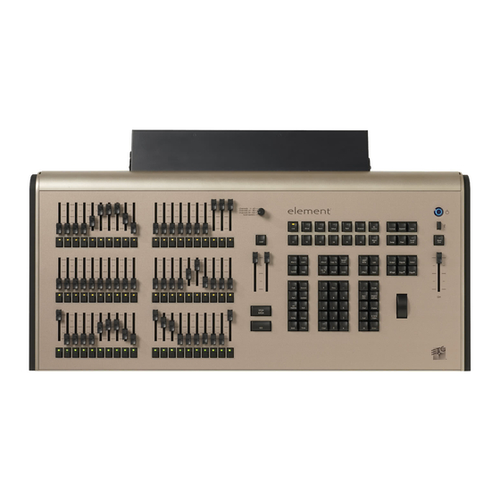
Console Geography Below is a diagram of Element with references made to specific areas of use. The terms and names for each area and interface are used throughout this manual. Fader Position Faders and Switch bump buttons Power button USB port... -
Page 25: Control Keypad Layout
Display and navigation keys are used for quick access to common displays, format, paging, and navigation within displays. The load button is located above the fader pair and is used to load the specified cue. Display Softkeys Special function controls Navigation Shift Record targets Numeric Keypad and and related modifiers commands Element Overview... -
Page 26: Terminology
W A R N I N G : Before servicing Element, you must switch off the power on the rear panel and disconnect the power cord completely. US B Ports One USB port is provided on the front of the console to connect any USB storage device. -
Page 27: Cleaning Element
O u t p u t ti n g D M X In order to output levels from Element, you can either use the DMX ports on the back of the console, or to output over a network, you may connect a Net3 gateway or Net2 node. If your devices receive Net3 or ETCNet2 directly, no gateway or node is required. -
Page 28: Console Capacities
F a d e r s • 1 Grandmaster with Blackout • 1 Master Playback, with Go and Stop/Back • 40 or 60 Faders with bump buttons • a maximum of 300 configurable submasters • 120 channel faders Element User Manual... -
Page 29: System Basics
C h a p t e r 3 System Basics This chapter will discuss using the basic Element displays. For more display information, see Display Conventions, page 245. This chapter contains the following sections: • The Central Information Area (CIA) . -
Page 30: The Central Information Area (Cia)
L o c k i n g t h e F a c e p a n e l It is possible to lock out the facepanel, which prevents any actions from the command line or CIA. To lock out the facepanel, press [Shift] & [Escape]. To unlock the facepanel, press [Shift] & [Escape] again. Element User Manual... -
Page 31: Using Softkeys
Using Softkeys Some of the features and displays in Element are accessible from the softkeys, which are located in the bottom right area of the CIA. Those softkeys correspond to buttons [S1] - [S6] and [More SK]. Pressing the [Browser] button accesses the following softkeys: •... -
Page 32: Clear Functions
From this menu you can select one of the available clear options by clicking on the desired button in the CIA. Element will ask you for a confirmation before performing the selected clear. For {Clear Targets}, Element will allow you to choose which record targets you want to clear. -
Page 33: Display Control And Navigation
F r o m t h e h a r d k e y s Several displays are opened directly from buttons on Element’s keypad. Those displays are [Live], [Blind], [Patch], [Setup], [Park], [Browser], and [ML Control]. You can open list views of any... -
Page 34: Scrolling Within A Display
When the [Time] button is pressed on a terminated command line, the selected cue is always displayed for time modification. [ L a b e l ] K e y Element allows for labeling of cues, channels, submasters, and more. Below are some examples of labeling syntax: N o t e : You will need a mouse, keyboard, or touchscreen to create labels. -
Page 35: Using Flexichannel
U s i n g F l e x i c h a n n e l Flexichannel (use of the [Flexi] key) allows you to view only channels meeting a certain criteria in the live/blind display, therefore removing unwanted data from view. Flexichannel has several available states which include allowing you to view: •... -
Page 36: Using [Format]
In live, table view displays all active channel data being output from Element. In blind, it will display all data for a single record target (cue, palette, submaster). -
Page 37: Zooming Displays
S u m m a r y V i e w The summary view displays the largest number of channels of any of the formats. Below you can see channels 1-80 are shown. This format is best used to see large numbers of channels’ intensity data or parameter category data. - Page 38 See “Recording and Editing Cues from Blind” on page 116. To toggle between viewing just the intensity information and other parameters, press [Shift] & [Format]. Cue numbers Channel number Parameters Element User Manual...
-
Page 39: Managing Show Files
C h a p t e r 4 Managing Show Files This chapter explains how to create, open, and save your show files. Each of these operations are accomplished through the browser area. This chapter contains the following sections: • Create a New Show File. -
Page 40: Create A New Show File
Press [Select] or click {OK} to confirm or {Cancel} to discontinue the operation. In Element, a new show file defaults to a 1-to-1 patch. Clicking {Patch 1to1} will deselect the option and result in a blank patch. - Page 41 (selected). To stop the show load process, click the {Cancel} button. When you have selected or deselected all of the show components you require, press [Select] or click {OK}. Element loads the selected show to the console. Managing Show Files...
-
Page 42: Selective Partial Show Opening
Target - The desired location of the components in the new show file (for ranges, this will be the location in the new show of the first component in the range, the others will follow in order). Element User Manual... -
Page 43: Merging Show Files
USB device. To merge a show file, navigate within the Browser to: File> Merge>. Navigate to the desired storage location and press [Select]. When using merge, Element displays only the available files. Navigate to the specific file and press [Select]. - Page 44 Target - The desired location of the components in the new show file (for ranges, this will be the location in the new show of the first component in the range, the others will follow in order). Element User Manual...
-
Page 45: Printing A Show File
Printing a Show File Element provides you with the ability to save a show file or aspects from a show file to a PDF file for printing. Element has three locations to save the PDF files including the Show File Archive, the File Server (if connected), or a USB device (if connected). -
Page 46: Saving The Current Show File
The PDF will have the show name, date and time it was created, and date and times for when the show file was last saved. It also gives the Element software version information. If multiple aspects were selected to save to the file, there will be hyperlinks at the top of the PDF so you can quickly jump to a section. -
Page 47: Using Save As
Using Save As To save an existing Element show file to a different location or with a different name, navigate within the browser to: File> Save As> and press [Select]. Element provides you with three locations to save an Element show file (.esf) including the Show File Archive, the File Server (if connected) or a USB device (if connected). -
Page 48: Exporting A Show File
Fast Focus Pro or Focus Track and select the location for the export, the Show File Archive, a File Server (if connected), or to a USB device. Deleting a File Element provides you with the ability to delete show files from the Show File Archive and the File Server from within the browser. To Delete a Show File Navigate within the browser to: File>... -
Page 49: Chapter 5 Setup
C h a p t e r 5 Setup This chapter discusses Element’s system settings that you can change to meet your preferences. This chapter contains the following sections: • Opening Setup ........38 •... -
Page 50: Opening Setup
{Num of Channels} You may use this field to set the number of channels in your Element up to 10,000. However, you are limited to only patch up to the number of channels that are available from your system, either 250 or 500 depending on the channel count for your Element. - Page 51 MIDI Show Control information. Only MSC data with the same device ID will be received. A device ID can be from 0-126, or if set to 127, Eos Ti, Gio, Ion, or Element will receive MSC data from all IDs (All Call).
- Page 52 This is a master setting for receiving analog inputs from a Net3 I/O Gateway or the local analog ports on a Gio, Ion, or Element. When disabled it will turn off all analog input for all event lists. Default is “Enabled”.
-
Page 53: Desk
{String RX Group IDs} This button is for setting up which Serial Port Group ID (from I/O Gateway settings in GCE) the console will listen to. This only affects serial traffic from I/O gateways, not network UDP messages or ACN strings. Group IDs are from 1-32. Remember group IDs relate to the number set in the gateway. - Page 54 [At]). Any value between 0-100 may be entered. The default is 100. Plus% - This sets the level for the +% (which is accessed in Element by pressing [Shift] & [+]), which will increase the selected channel by the set percentage. Any value between 0- 100 may be entered.
- Page 55 By default, this is “Disabled”. { D i s p l a y s } This desk setting button gives you access to the Element display settings. High Contrast Display This button toggles the setting between “Enabled” and “Disabled”. When enabled, high-contrast brightens the magenta used to show tracked values.
- Page 56 X and Y, respectively. When this button is enabled, Pan and Tilt will be Y and X. {Reverse Pan} This touchbutton reverses the direction of Pan. {Reverse Tilt} This touchbutton reverses the direction of Tilt. {Reset} This button resets all five trackball settings back to their default. Element User Manual...
-
Page 57: Chapter 6 Patch
C h a p t e r 6 Patch The Patch is used to associate a channel with an address. Once a channel is patched to an address, and the output is connected to a device (for example a dimmer, moving light, or accessory), the channel will then control that device. -
Page 58: About Patch
This is referred to as a compound channel. When you open a new show file, Element creates a 1-to-1 patch. This means that the patch will automatically have channel 1 patched to address 1, channel 2 to address 2, and so on up to the maximum channel count of your console. -
Page 59: Displays
Displays To begin patching your show, you must first open the patch display. To open the patch display, press press [Displays] and then {Patch}. The patch display will open on an available external monitor and the CIA will display patch controls. If there are no monitors attached, patch will open on one of the on-board monitors. -
Page 60: Patching Conventional Fixtures
For patching fixtures, there are two different patch modes: patch by channel and patch by address. Element defaults to patch by channel mode. Pressing [Format] while in the patch display will toggle the mode between patch by channel and patch by address. -
Page 61: [At] [Next]
N o t e : If, at any point, you try to patch an address that is already in use, Element will post an advisory to indicate this, preventing you from duplicating addresses in your patch. -
Page 62: Flexichannel Views In Patch
• [Dimmer/Address][2] [/] [Copy To] [Copy To] <Address> [3] [/] [Enter] - moves all channels with addresses in universe 2 to the same offsets in universe 3. • [Dimmer/Address] [n] [/] {Unpatch} - unpatches all patched addresses in the selected universe. Element User Manual... -
Page 63: Creating Multi-Part And Compound Channels
By default, Element will add a part if you are trying to patch to a channel that has already been assigned an address. -
Page 64: Patching Scrollers
Notice the two softkeys {Favorites} and {Manfctr} located beneath the CIA. {Favorites} provides you with the option of showing only the library of fixtures or devices that are already patched in the show, your favorites, and Element’s default devices. {Manfctr} shows all fixtures or devices available in the library sorted by manufacturer. -
Page 65: Using The Scroller Editor
Using the Scroller Editor The scroller and wheel picker allows you to choose a specific scroll, color wheel, gobo wheel, or effect wheel from standard manufacturers and associate them with fixtures. You may also create customized scrolls or wheels using the editor to match custom devices installed in your fixture. N o t e : Scrollers and wheels can be created before being patched. -
Page 66: Using The Editor
When using the editor, the following softkeys are available for use: • {Insert} - inserts a new frame above the selected frame. • {Delete} - removes the selected frame. • {Edit} - changes the selected frame. • {Done} - completes the editing process. Element User Manual... - Page 67 C r e a t i n g a n e w s c r o l l o r w h e e l When you create a new scroll or wheel, {New Wheel x} appears in the wheel list as the selected button.
- Page 68 When a specific catalog is selected, the media will display in the last three columns of the editor. When you make a media selection, the display returns to the new wheel frame list where additional frames can be edited in the scroll or wheel. Element User Manual...
- Page 69 S c r o l l e r C a l i b r a t i o n C o l u m n Calibration can also be done from the scroller calibration column. Values in grey are default data, and the values in blue are calibrated data.
-
Page 70: Calibrating A Scroller
Use the scroller encoder to adjust the centerpoint of a frame. It is recommended that you start with the last frame in the scroll. Step 5: When the frame is centered, click {Calibrate}. Step 6: Repeat for any remaining frames that need to be calibrated. Scroller Encoder Frame Picker Element User Manual... -
Page 71: Patching Moving Lights, Leds, And Accessories
{Favorites} provides you with the option of showing only the library of fixtures or devices that are already patched in the show, your favorites, and Element’s default devices. {Manfctr} shows all fixtures or devices available in the library sorted by manufacturer. -
Page 72: Using {Offset} In Patch
• [1] [Thru] [2] [0] {Offset} [2] {Type} {VL1000} [At] [1] {Offset} [2] [0] [Enter]- selects every other channel in the list and patches them with an offset of 20 addresses. Element User Manual... -
Page 73: Display Pages In Patch
{ P a t c h } D i s p l a y a n d S e t t i n g s When in the patch display, Element defaults to this page. It provides access to data input fields that you may use to define devices in your lighting system. - Page 74 See “Using Output Address vs Port/Offset” on page 50. • You may enter a start address without defining an end address. Element will draw this information from the library data. If you wish to leave a larger output gap than required by the library, use [Offset].
-
Page 75: Attributes
A t t r i b u t e s The {Attributes} area of patch provides you with optional fields for additional information and details relating to your patched fixtures. The {Attributes} settings that apply to conventional fixtures are {Preheat}, {Proportion}, {Curve}, and {GM Exempt}. - Page 76 {Effect Wheel} button on the CIA to display the wheel picker with effect options available for your device. See “Using the Picker” on page 53. • [5] {Attributes} {Effect Wheel} - selects channel 5 and opens the wheel picker in the CIA for effect wheel selection. Element User Manual...
-
Page 77: Database
D a t a b a s e N o t e : Database is used with the query feature, which is not available on Element. However since show files are compatible between the Eos Family consoles, the database is available on Element. -
Page 78: Using Device List
See “Interface Protocols” on page 236. Open the Dimmer Feedback display while in the patch display by pressing {Device List}> {Dimmers}. When the dimmer list is opened, the dimmers will be displayed in Patch by Address mode Element User Manual... - Page 79 The System ID number from CEM3 is not currently supported. N o t e : Rack numbers and dimmer numbers need to be unique for Element to properly recognize them. For CEM+, dimmers also need to be patched to different sACN addresses.
-
Page 80: Rdm Device List
Element will also display what personality from the Element library the device matches in the Element Type column. This information will not display until you first select the device. Once the device has been selected for the first time, Element will extract the type information from the device and display it. - Page 81 With a device or devices selected, you can edit various device settings in the property view, which will display in the CIA. Items with a caret (>) are editable. When multiple devices are selected together for editing, an “*” will show for data that is different between the selected devices. The following buttons will also display in the property view: •...
-
Page 82: Patching Discovered Dimmers And Rdm Devices
P a t c h i n g D i s c o v e r e d D i m m e r s a n d R D M D e v i c e s When dimmers/devices are discovered, they are not automatically attached to any patched channels in Element. If you want the benefits of dimmer or RDM feedback, you must attach a dimmer or device to a channel. -
Page 83: Detaching Devices
• Yellow “?” means that the dimmer/ device has a warning message.Warning messages can include: • Multiple devices’ addresses overlap • Multiple devices of different devices at this address • Patched fixture type mismatch • Patched fixture address mismatch • Offline D e t a c h i n g D e v i c e s Pressing {Attach} twice will post the {Detach} command. -
Page 84: Dimmer Doubling
Dimmer Doubling You can patch channels in Element to accommodate for dimmer doubling with Sensor dimmer racks. This is done using the softkeys available in patch ({No Dim Dbl}, {A}, and {B}). N o t e : Dimmer Doubling is only available over the network. -
Page 85: Swapping Channels
Swapping Channels Channels can be swapped for each other in patch: • [1] {Swap} [2] [Enter] This syntax will replace channel 1's data with channel 2's and vice versa in patch and throughout the entire show. N o t e : Move To and Swap always impact the entire show. -
Page 86: Clearing The Patch
{Cancel} from the confirmation screen. Update Library When a new library is installed on Element (for example, included in a software update), changes in library data will not automatically update your show files. This is to prevent library changes from affecting a functional show file. -
Page 87: Fixture Editor
Fixture Editor Element provides you with the ability to create your own fixture type within patch and store it with your show file. You can name the fixture, assign all necessary parameters, define the address and operational range of those parameters, and set lamp controls. - Page 88 {Intensity}, {Focus}, {Color}, {Image}, {Form}, {Shutter}, or {Control}. {All} returns you to the complete list of parameters. b: Use the parameter category buttons on the left of the CIA to expedite searching for a particular parameter. Element User Manual...
- Page 89 C A U T I O N : Be careful not to duplicate any address in the DMX order of parameters in the new fixture. Element does not prevent you from duplicating addresses. To define the LDMX address of any 16-bit channel: LDMX or “low-DMX”...
- Page 90 If you are missing a control slot: at any point you can use the [Page] keys and {Insert}, to insert a slot above the selected one. If you want to remove a lamp control: you can use the [Page] keys and {Delete}, to remove a lamp control from the list. Element User Manual...
-
Page 91: Copying A Fixture
To add steps to a lamp control: Step 1: Use the [Page] keys to navigate to a control slot. Step 2: Click {Steps} to add steps. The steps list will open. Step 3: Determine the total number of steps required for the control. Step 4: Click {New} to add steps. -
Page 92: Snap Parameters
S n a p P a r a m e t e r s Certain parameters may not want to be subjected to cue timing. Those parameters can be set to snap. By default, Element will snap the parameters listed in the following table: Beam FX Index/... -
Page 93: Basic Manual Control
C h a p t e r 7 Basic Manual Control Element provides a variety of ways to select and command control channels. This chapter identifies the many basic ways you can select channels and manipulate show data within Element. -
Page 94: Using Channel Faders
Using Channel Faders One way to bring up channel levels with Element is using the channel faders. The fader position switch is used to select between channels 1-40, channels 41-80, or channels 81-120. Element will ship with the fader position switch in channels 1-40 mode. -
Page 95: Selecting Channels
Selecting Channels Selected channels are available for manual control through keypad commands, level wheel, and/or ML controls. Element provides interactive ways to select channels including the control keypad and groups. See “Selecting Groups” on page 123. S e l e c t C h a n n e l s F r o m t h e K e y p a d The keypad defaults to selecting channels. -
Page 96: Offset
N o t e : Select Last is a fast way to regain your last channel selection. Any manual control action taken while record or update is on the command line will automatically reselect your last channel selection. Element User Manual... -
Page 97: Setting Intensity
Setting Intensity Channel intensity may be set using the channel faders, by selecting the channel(s) and using the level wheel or the keypad, or set with an intensity palette (if programmed, See “Using Intensity Palettes” on page 126.). Pressing [At] after channel selection allows you to enter a discrete intensity value. -
Page 98: Level Wheel
Using +% and -% Use +% and -% to incrementally change parameter values. To access this function on Element, press [Shift] & [+] or [Shift] & [-]. By default, +% and -% are assigned a value of 10. This can be... -
Page 99: Remainder Dim
Remainder Dim [Rem Dim] temporarily provides an intensity level to all channels except those that are currently selected, those that are parked, or those with intensity contributions from submasters. When the remainder dim command is cleared, the stage returns to its previous state. The default remainder dim value is 0, but this can be changed in Setup. -
Page 100: Sneak
• [Shift] & [Sneak] - makes any manual data unmanual. The values will remain but they will no longer be available for [Update] or [Record Only] operations. When used with an empty command line, this will affect any and all manual data. When used with a channel selection, only those channels will be affected. Element User Manual... -
Page 101: Channel Check
Channel Check Channel check allows you to quickly step through all of your patched channels. This is useful for checking lamps or checking focus. N o t e : Parked dimmers will not be affected by the channel check feature. The following examples illustrates the how to use the channel check feature: •... -
Page 102: Flash
Moving Light Control For more information about the ML Control display, see Moving Light Control, page 136. For more information on programming moving lights, please see the Element tutorials, http:// www.etcconnect.com/product.tutorial.aspx?ID=22010. Element User Manual... -
Page 103: Storing And Using Submasters
C h a p t e r 8 Storing and Using Submasters Submasters are intensity levels and non-intensity parameters recorded to a fader for simple playback. This chapter explains how to record and use submasters on your Element console. This chapter contains the following sections: •... -
Page 104: About Submasters
5 to submaster 3, that would be added to the current content so that channels 5 through 10 are now stored. Record only can be used when recording submasters, for more information see Using Record Only, page 101. Element User Manual... -
Page 105: Submaster Displays
A d d i t i v e , I n h i b i t iv e , o r E f f e c t s u b You may define your submaster as additive (contributes to the live output), inhibitive (limits live output), or effectsub (controls an effect). Element defaults to submasters being additive. To toggle a submaster between additive, inhibitive or effectsub: •... -
Page 106: Htp Vs. Ltp
H T P v s . L T P Submasters can be set to be either Highest-Takes-Precedence (HTP) or Latest-Takes-Precedence (LTP). This setting is applied to intensity only. Non-intensity parameters are always LTP. Element defaults all submasters to HTP. For more information on HTP and LTP see HTP vs. -
Page 107: Submaster Background State
To toggle a submaster between priority modes: • [Sub] [7] {Priority} [Enter] S u b m a s t e r B a c k g r o u n d S t a t e Submasters can have their background states disabled. Background states are enabled by default. When enabled, the content of the submaster will act as a background or previous state for other cues and submasters. -
Page 108: Deleting A Submaster
Element has a total of 300 submasters. With the fader position switch in submaster mode, an Element 60 will display 60 submasters, and an Element 40 will display 40 submasters at a time. Element will default to the first 40 or 60 submasters. To page through the available submasters, hold down the {Page Subs} softkey in the live display. -
Page 109: Using Bump Button Timing With Submasters
Using Bump Button Timing With Submasters Submasters may be raised manually using the fader, or they may be executed with timing using the bump button. Normally the bump button snaps the contents of the submaster to full when pressed, and to zero when released.Each submaster bump can have three different timing values: Upfade, Dwell, and Downfade (see below). -
Page 110: Submaster List
You may also press [Blind] and select the required submaster from the command line. Any changes made in this screen are automatically stored. A [Record] or [Update] command is not required. Changes made in blind to active submasters are immediately routed to live output. Element User Manual... -
Page 111: Working With The Cue List
C h a p t e r 9 Working with the Cue List Cues are recorded stage looks including levels for intensity and non-intensity parameters. Cues are different from submasters in that they are stacked in a cue list, and they allow few or many intensity and non-intensity values to change in recorded times based on a single [Go] button press. -
Page 112: Basic Cueing
Typically, cues are written in order, starting with the first look of a show, then moving on through each scene, recording new cues when lighting levels need to change. In setup, you determine if Element will operate in a Cue Only or Tracking mode. See “Tracking vs. -
Page 113: Recording Cues In Live
Recording Cues in Live When using [Record], all parameters of any lights that have non-default values, either from manual control, other cues, or submaster playback are stored in the target cue. When cues are recorded, they are automatically played back, and manual values are released, unless auto playback on record has been disabled in setup, See “Auto Playback”... -
Page 114: Selective Storing Cues Using [Record]
• [-] [9] [Record] <Cue> [5] [Enter] - records cue 5 while excluding channel 9. Since Element is a tracking console, any channels not included in the selective store, but that do have values in the previous cue will track into the recorded cue. This is true even when the desk is in Cue Only mode. -
Page 115: Using [Cue Only / Track]
I n T r a c k i n g M o d e Element, by default, is set to Tracking mode. When you create a new cue, any unchanged channel parameter data from the previous cue is tracked into the new specified cue. Any changes in this new cue will also track forward into subsequent cues until a move instruction or a block flag is encountered. - Page 116 • [-] [5] {Color} [Record] <Cue> [6] [Track] [Enter] - records the specified cue, except the color data from channel 5. The data will track forward in the list until the next move instruction or block. Element User Manual...
-
Page 117: Move Fade
To force a cue to “stomp” on currently fading levels, like in the case of a blackout at the end of a scene, place a block on that cue. In Element, the block will also assert the 0 levels in the blackout and force all moving channels to fade to black. -
Page 118: Timing
S e t t i n g C u e L e v e l T i m i n g Unless you specify otherwise, Element assigns default fade times to any cue you record. Default timing is designated in Setup. Timing can be applied when a cue is recorded or can be modified later. -
Page 119: [Time][/]
M a n u a l T i m i n g a t a C u e L e v e l Manual times are assigned by using the {Manual} softkey that is displayed when recording a cue. For more information on manual timing, see Manual Timing Control, page 132. - Page 120 4 times (once plus 3 loops) and then stop in cue 2. The loop value specifies the number of times the loop instruction will be performed. Since the sequence has run once prior to the loop command, the total number of passes will be the specified number of loops Element User Manual...
-
Page 121: Clearing Cue Attributes
Rate The {Rate} softkey can be used to apply a rate adjustment to all timing in the cue. The default rate is 100%, which is real time. To slow a cue down, set the rate below 100%. To speed the cue up, set the rate above 100%. -
Page 122: Flags
NPs. I is displayed in the Block field. Element also supports an “auto block” function. Auto block can protect your cue data from unwanted changes. For example, in cue 5 you set channel 1 to 50%. It is stored as a move instruction. -
Page 123: Preheat
to cue 5. Channel 1 will be “auto blocked” in cue 5. Even though it is now at the same value as the previous cue, the original concept of a move instruction is maintained. When the block instruction has been recorded, updated, or stored while in blind, any tracked values the block was applied to will be displayed in white. -
Page 124: Modifying Cues Live
Cues can also be modified using selective storing, which allows you to specify only the channels and or parameters that you want to store. When using a selective store, you must specify the channel list to be included or excluded, identified by [Thru], [+], [-], as part of the [Record] command. Element User Manual... -
Page 125: [Update]
When you have overridden a reference in a cue, the data is displayed in red with a red “R” in superscript next to the channel’s intensity. By default, Element updates any referenced data that was included in the cue. For Example: Cue 5 is recalled Live. - Page 126 5. The recorded changes will track forward in the list. • [Update] <Cue> [3] [Thru] [7] [Track] [Enter] - updates cues 3 thru 7. Range updates are subject to the normal rules of track/cue only in determining impact on subsequent cues. Element User Manual...
- Page 127 U s i n g T r a c e {Trace} works just as Track does, except it allows changes to be tracked backwards through the cue list, until it sees a move instruction. A trace will track into, but not beyond, a move or a blocked instruction.
-
Page 128: Recording And Editing Cues From Blind
{Trace} can also be used to have changes trace back to the initial move instruction. Such as: • [1] [Thru] [5] [At] [5] <0> [Cue Only/Track] [Enter] -or- • [1] [Thru] [5] [At] [5] <0> [Cue Only/Track] {Trace} [Enter] Element User Manual... -
Page 129: From The Cue Spreadsheet
T o L i v e F r o m B l i n d From blind, a softkey {Live} is posted when you press [Recall From] or [Copy To] to allow you to copy to or recall information from live. The following examples only work with the {Live} softkey, not the [Live] hard key. - Page 130 Any values in the cue after cue 2 that tracked from moves in cue 2 are changed to move instructions. Ranges of cues can be moved as well. If any cue is to be overwritten, a confirmation is required. Element User Manual...
-
Page 131: Deleting Cues
Deleting Cues Cues or ranges of cues can be deleted. When deleting cues, the track/cue only setting of the console will determine how subsequent cues are affected. The [Cue Only/Track] button can be used to modify the default behavior as needed. I n T r a c k M o d e When the console is in track mode, deleting a cue also removes any move instructions provided by the cue. - Page 132 Element User Manual...
-
Page 133: C H A P T E R 1 0
C h a p t e r 1 0 Using Groups and Intensity Palettes Groups are stored channel selections used for fast recall of specific channels. Intensity palettes are referenced data that include channels, but also include intensity settings for those channels. A maximum of 1000 groups and 1000 intensity palettes can be recorded. -
Page 134: Recording Groups Live
[1] [0] [Thru] [2] [Record] [Group] [1] [Enter This will record channels 10 through 2 to Group 1, and then if you select the group you can cycle through the channels using [Next] starting with 10, then 9, then 8, and so on. Element User Manual... -
Page 135: Offset
O f f s e t You can use the {Offset} softkey to aid in channel selection prior to storing groups. The offset options are {Odd}, {Even}, {Reverse}, {Random}, and {Reorder}. For example: • [1] [Thru] [9] {Offset} {Odd} [Record] [Group] [5] - records all odd numbered channels between 1 and 9 to Group 5. -
Page 136: Group List
• {Random} [Enter] - rearranges the channels in the group randomly. • {Reverse} [Enter] - reverses the order of the channels within the group. • {Reorder} [Enter] - reorders the channels to numeric order in the group selected. Element User Manual... -
Page 137: Recording Intensity Palettes Live
Recording Intensity Palettes Live Palettes are referenced data. This means that when included in cues or effects, changes to the contents of the palette are propagated into all of the places the palette is stored. Intensity palettes contain both channel and intensity information. Groups only contain channel selection information. Intensity palettes can be stored as whole numbers (such as Intensity Palette 5) or as decimals of tenths or hundredths (such as Intensity Palette 2.5 or Intensity Palette 7.65). -
Page 138: Using Intensity Palettes
Calling back the intensity palette at full will also break this link. For more information on using intensity palettes, please see Using Moving Lights and Palettes, page 135. Element User Manual... -
Page 139: C H A P T E R 1 1
C h a p t e r 1 1 Cue Playback The playback section includes descriptions of working with the master fader pair, Grandmaster, load button, and the fader control softkey. • Introduction to Playback ......128 •... -
Page 140: Introduction To Playback
The two buttons beneath the master fader pair are [Go] and [Stop/Back]. The [Load] button is located directly above the fader pair. P l a y b a c k C o n t r o l s Master Load button fader pair Stop/Back Grandmaster Button Go button Element User Manual... -
Page 141: Selected Cue
Selected Cue The selected cue is always indicated just above the CIA. The selected cue and all of its attributes are displayed near the bottom of the live/blind display and on the playback status display. L i v e / B l i n d When working in live, the selected cue is always the last cue you recorded, edited, updated or played back. -
Page 142: Out-Of-Sequence Cues
• [Go To Cue] [8] [Time] [Enter] - this command would take you to cue 8 using all timing values stored in cue 8, and all associated follow times. • [Go To Cue] [3] [Time] {Manual} [Enter] - sets up the selected cue for manual control using the master fader pair. Element User Manual... - Page 143 O t h e r G o T o C u e o p t i o n s When [Go to Cue] is pressed, the softkeys in the CIA are changed to provide Go to Cue modifiers to enhance your playback ability. From these softkeys, you can specify that when going to a cue, only some elements of that cue will be played back.
-
Page 144: Playback Fader Controls
Manual timing can be set for any parameter or group of parameters. The fader is then used to control the progress of a transition. For Example: Assume the active cue contains an instruction to set color at 5 for channel 1. Element User Manual... - Page 145 The pending cue contains an instruction to set channel 1 to color 12 and the color parameter has a manual time. Press [Go] to activate the cue. Channel 1 color does not change. As you move the fader up manually, channel 1 color moves proportionally from color 5 to color 12.
-
Page 146: Manual Master Option
See “Proportional vs. Intensity Master” on page 93. When manual master has been selected as the fader mode for a cue list, the initials ‘MM’ will appear above the cue list label field. Initials ‘IM’ will display when set to intensity master mode. Element User Manual... -
Page 147: C H A P T E R 1 2
C h a p t e r 1 2 Using Moving Lights and Palettes This chapter will briefly look at Element’s moving light controls as well as discussing how to use focus, color, and beam palettes. Palettes are building blocks that can be used to create cues and effects. -
Page 148: Moving Light Control
• 12 ....Virtual encoder (Click and hold close to the center line for slow movement, further away for faster movement.) Element User Manual... -
Page 149: Using The Color Picker
U s i n g t h e C o l o r P i c k e r The button {Color Format} is for toggling between native (RGB, CMY, color scroller, or color select) and hue and saturation. {Gel} is for opening up manufacturer catalogs of gels. To display a specific manufacturer’s catalog, press the specific manufacturer or catalog and select the desired gel. -
Page 150: Adjusting Parameters Using + And
• [1] [1] [Enter] [About] {Lamp Cntrls} This screen displays any lamp controls associated with the selected channel (this is also the “Lamp Control” subscreen of About). If the channel is a conventional (intensity-only) fixture, no parameters Element User Manual... -
Page 151: Automark
will be displayed. When the selected channel is an automated luminaire, options specific to the fixture type will display for use. Pressing any of these parameter control buttons will affect the selected channel after a confirmation. Exit the lamp controls display by pressing [Browser]. A u t o M a r k The AutoMark feature is a system default setting and can be turned off on a cue-by-cue basis if required. -
Page 152: About Palettes
Intensity, Focus, Color, and Beam. Element supports up to 1,000 palettes of each of the four types. Palettes can be recorded as decimal or whole numbers and are automatically filtered into IFCB categories. Color data cannot be placed in beam palettes, intensity cannot be included in focus palettes, and so forth. -
Page 153: Storing Palettes Live
Storing Palettes Live Palettes may be stored in live or blind. N o t e : To be able to record and label palettes, you will need a mouse or touchscreen. S t o r i n g P a l e t t e s w i t h [ R e c o r d ] The most common method to create palettes is to store them from Live. -
Page 154: Storing Palettes With Record Only
• [1] [Thru] [9] {Iris} {Zoom} [Record] [Record] {Beam Palette} [5] [Enter] - stores only manual zoom and iris data for channels 1-9 to beam palette 5. Element User Manual... -
Page 155: Using Palettes
Using Palettes Intensity palettes can be from the control keypad, and Focus, Color, and Beam palettes are selected from the ML Control display. When palettes are recalled, all data is manual and will display in red. A p p l y i n g P a l e t t e s Generally, palettes are applied only to selected channels, therefore you must select channels before applying a palette. -
Page 156: Recalling Palettes
As long as channel 3 was previous recorded in color palette 5, channel 3 will now be set to color value recorded in that palette. In this case, the channel is not referencing the palette. It has been given the absolute value as stored in the palette. Element User Manual... -
Page 157: Editing Palettes Live
Editing Palettes Live N o t e : If a palette is already recorded, [Record] replaces all existing data, unless selective store is used. [Record Only] is a selective store, therefore it adds data. Recording over a previously existing palette requires a confirmation, if confirmations are enabled in the setup menu. -
Page 158: Editing Palettes In Blind
When editing in blind, it is possible to remove an instruction from any palette by selecting the channel and parameter and pressing [At] [Enter]. [Recall From], [Copy To], {Replace With}, and {Move To} may be used to create and edit palette data. See “Advanced Manual Control” on page 177. Element User Manual... -
Page 159: Editing Palettes In Spreadsheet View
• [palette type] [1] [Thru] [5] {Move To} <palette type> [9] <Thru> [Enter] - this will move palettes 1-5 to palettes 9-14 respectively. You do not have to supply the end value for Element to perform the move. - Page 160 Element User Manual...
-
Page 161: C H A P T E R 1 3
C h a p t e r 1 3 Creating and Using Effects Effects are a method within Element to provide dynamic, repetitive action to channels. This chapter explains the different types of effects, and how to use them. This chapter contains the following sections: •... -
Page 162: About Effects
Effects also have cue level overrides, which allow you to use an effect in multiple locations, and modify its size, shape or rate in individual cues. Within Element, effects are broken up into three fundamental behavior types; Step, Absolute, and Relative effects. -
Page 163: The Effect List
T h e E f f e c t L i s t At any time you may press [Effect] [Effect] to view the effect list. Any recorded effects will be displayed here. The effect list is a blind view and any changes made in this view are automatically stored;... -
Page 164: Effects Editor
In these effect types, modifying the cycle time changes the timing values proportionally within the effect itself. To change the cycle time, click {Cycle Time} and then enter the desired time (in minutes and seconds) from the keypad, followed by [Enter]. Element User Manual... - Page 165 Duration/Cycle This determines the length of time an effect will run. To specify, click {Duration/Cycle} and then choose the desired method from the buttons that appear to the left. The options are: • {Infinite} - for step and absolute effects, the effect will run until the channel is provided a new instruction or the effect is stopped.
- Page 166 These timing values are applied to the entry and exit modes. You can also use cue level timing or submaster bump button timing for these. click {Entry Time} [Enter] or {Exit Time} [Enter]. Cue/ Sub is the default entry/ exit timing for effects. Element User Manual...
- Page 167 Grouping defaults to {Spread}. This means that every light the effect is applied to will act as an individual element, moving through the effect sequentially based on the channel selection order, cycle time, and trail times. You can enter any number you require. A grouping of 2 means that every other light in the selection list when the effect is applied will move together through the effect.
-
Page 168: Effect Status Display
• {Rate} [Enter] - resets the rate to the previous value. These modifications are considered cue level overrides and do not impact the stored values in the effect. Modifications made via the effect status display or live editing must be stored/updated. Element User Manual... -
Page 169: Step Effects
Step Effects In step effects, each step contains an on-state and an off-state. The on-state is the action the channels in the step should take when the step is active. The off-state is the action the channels in the step should take when the step is not active. Step effects are a quick and easy way to build simple chases. -
Page 170: Program A Step Effect
The cycle time is an aggregate of all of the timing in the effect and indicates how long it will take to make one full pass through the effect. If the cycle time is modified by the keypad or the encoder, it proportionally adjusts all of the timing within the effect. Element User Manual... -
Page 171: Absolute Effects
D e l e t e a s t e p To delete a step from a step-based effect, specify the effect in the command line and press [Delete]: • [Effect] [1] {Step} [4] [Delete] [Enter] [Enter] • [Effect] [1] {Step} [4] [Thru] [8] [Delete] [Enter] [Enter] I n s e r t a s t e p To insert a step anywhere in the effect, specify the step you wish the new step to be inserted before. -
Page 172: Program An Absolute Effect
Page arrow down to the next action in the Level column and enter the referenced target: • {Color Palette 4} Adjust any of the effect details on the right side of the CIA by pressing the appropriate detail button and making changes (see Effects Editor, page 152). Element User Manual... -
Page 173: Multiple Intensity Htp Effects
Relative effects have many of the same properties and attributes as step-based and absolute effects. Element is preprogrammed with 16 relative effects which represent some of the most commonly used patterns and parameters. You may also custom build relative effects. -
Page 174: Color Effects
You can redraw the linear diagram for an existing linear effect by pressing {Edit}>{Clear} and then tracing the diagram on the graph with the mouse or your finger. Press {Apply} when you are done. Linear Effect Element User Manual... -
Page 175: Define A Pattern Shape
D e f i n e a P a t t e r n S h a p e Shapes can be defined for any relative effect (focus, color, or linear). N o t e : You will need to use a mouse or touchscreen for shape definition. To define a shape, press the {Edit} softkey beneath the pattern editor. -
Page 176: Apply An Existing Effect
D e l e t i n g a n E f f e c t To delete an effect, press: • [Delete] [Effect] [n] [Enter] [Enter]. If you delete one of the default effects (901 through 916) that effect will return to its default values. Element User Manual... -
Page 177: Effects On Submasters
Effects on Submasters Channels running effects can be loaded onto a submaster. Pressing the bump button of the submaster starts or stops the effect. For the submaster fader to control the rate and/or size of the effect, it must be configured as an effects submaster. -
Page 178: Delaying Effects In Cues And Submasters
A delay column has been added to the Effect Status display. When an effect is in delay mode, the column will display the countdown for the delay. When an effect is delayed, a “*” will display by the effect number in the playback status display external links column. Element User Manual... -
Page 179: C H A P T E R 1 4
C h a p t e r 1 4 Using About [About] provides detailed information regarding selected items. When opened, it appears in the CIA and remains open until closed or until another action forces it to close. This chapter contains the following sections: •... -
Page 180: About [About]
• {Lamp Controls} - this displays lamp on, lamp off, any parameter reset commands, and available RDM commands associated with the channel. If it is a moving light with remote- strike and/or reset functions, this key will access those controls. If the channel controls dimmers, no parameters will be displayed. Element User Manual... -
Page 181: [About]
IP Address A b o u t S y s t e m When {About System} is pressed, the CIA displays a list of all network devices that are connected to Element. These network devices include: • Net3 RVI •... - Page 182 Clearing CEM+ / CEM3 errors from Element will be temporary unless the errors have been fixed at the CEM+ / CEM3. Errors displayed on Element will clear on their own once they have been cleared from the CEM+ / CEM3. Some CEM+ / CEM3 errors can only be cleared at the CEM+ / CEM3.
-
Page 183: About Channel
A b o u t C h a n n e l Press [About] to put the CIA into “About” mode. When a channel is selected, the information below is displayed: You can select the information you wish to view from the buttons located on the right side of the CIA. - Page 184 List of all parameter values with their address, home value, snap parameter, DMX value, and parked value (if any) {Lamp Controls} displays controls for the lamp, available RDM commands, or other parameters of the device (if it is a moving light). Click to go to About Address Element User Manual...
-
Page 185: About Address
A b o u t A d d r e s s Press [About] to put the CIA into “About” mode. When an address is selected, the information below is displayed. You can select the information you wish to view from the buttons located on the right side of the CIA. - Page 186 Clearing CEM+ / CEM3 errors from Element will be temporary unless the errors have been fixed at the CEM+ / CEM3 Errors displayed on Element will clear on their own once they have been cleared from the CEM+ / CEM3. Some CEM+ / CEM3 errors can only be cleared at the CEM+ / CEM3.
- Page 187 {Device Details} - appears when the current address is patched to a RDM device. RDM devices must be enabled through the ECU and discovered through the patch. See Enable RDM, page 236 {Patch} Display and Settings, page {Device Details} displays the information that it receives from the device and allows some changes to be made to: N o t e : Changes may take a few seconds to take effect.
-
Page 188: About Cue
• list of cues that use the effect N o t e : Any cues or submasters that have overrides, such as rate, for the effect will display an *. Element User Manual... -
Page 189: C H A P T E R 1 5
C h a p t e r 1 5 Advanced Manual Control This chapter describes some more advanced features for manual control functions. These features can save you valuable programming time. This chapter contains the following sections: • Using [Copy To] . -
Page 190: Using [Copy To]
Channels 1 and 2 are at 50% in cue 10, and in cue 11 channel 1 is at 10% and channel 2 is at full. If you are in cue 11, and use the syntax: • [1] [Thru] [2] [Copy To] [Cue] [1][0] {HTP} [Enter] Channel 1 will remain at 50% and channel 2 will go to full. Element User Manual... -
Page 191: Using [Recall From]
Using [Recall From] [Recall From] is similar to [Copy To], except that it retrieves data from other locations, and can be used only for a channel list recalling from the same channel list but in a different location (for example, a cue). [Recall From] is essentially a “copy from” command. You may recall all parameter data for selected channels, or by using the IFCB category buttons in the ML Control display, you may recall subsets of channel data. -
Page 192: Using {Move To
When a {Move To} command is given, data is removed from its current location and moved to its new location. If the new location already contains data, a confirmation is required by Element (unless disabled in Setup). Existing data in the new location will be completely overwritten if a {Move To} command is confirmed. -
Page 193: Using [Undo]
Using [Undo] Undo is a method to reverse or “undo” certain operations performed in the software.You can use [Undo] to reverse any command that results in a change to data that would be saved to the show file or any command that changes manual levels in live. If there are any commands in the command line, pressing [Undo] once clears the command line. - Page 194 Element User Manual...
-
Page 195: C H A P T E R 1 6
C h a p t e r 1 6 Using Park This chapter describes using park functions from both the live and park display. This chapter contains the following sections: • Park Display ........184 •... -
Page 196: Using Park
When an address is parked, it will appear in the bottom half of the park display. The address, parked value, affected channels, and parameters are indicated. Element User Manual... -
Page 197: Parked Values In Live
P a r k e d V a l u e s i n L i v e Channels and parameters may be parked and unparked from the live display. To park from the live display, you will use the {Park} softkey. Following are some examples: N o t e : Parked values will only be displayed in the park display. -
Page 198: Park Values From The Park Display
Below are examples for parking addresses in the park display: • [Dimmer/Address] [5] [At] [5] [0] [Enter] - parks address 5 at 50% intensity. • [Dimmer/Address] [5] [At] [Enter] - unparks address 5. Parked addresses Parked channels Element User Manual... -
Page 199: Multipart Cues
C h a p t e r 1 7 Multipart Cues Cues can be divided into up to 20 parts. This chapter describes the methods used to create and edit multipart cues. This chapter contains the following sections: • About Multipart Cues. -
Page 200: About Multipart Cues
Part 1 of any multipart cue is where all unassigned move instructions will reside. Therefore, if the body of the cue (which is the normal behavior) is to be in part 1, you can simply select the channel or parameter list that you wish to place in parts 2 and higher. Element User Manual... -
Page 201: Setting Multipart Cue Attributes
S e t t i n g M u l t i p a r t C u e A t t r i b u t e s Cue attributes, such as [Time], [Delay], and [Label] can be assigned in part cues. They are stored and function exactly as they do in single part cues. -
Page 202: Storing A Multipart Cue In Blind
[At] [Enter] or null them. • [Delete] <Cue> [1] [Part] [1] [Enter] [Enter] • [Delete] <Cue> [6] [Part] [1] [Cue Only/Track] [Enter] [Enter] • [Delete] [Part] [1] [+] [2] [Enter] [Enter] • [Delete] [Part] [1] [Thru] [3] [Enter] [Enter] Element User Manual... -
Page 203: C H A P T E R 1 8
C h a p t e r 1 8 Storing and Using Curves A curve is a relationship between the timing of a fade and the output level of a cue, cue part, or dimmer at each point of time during that fade. By using a non-linear curve, you can create a variety of effects, accommodate variations and deficiencies in your lighting equipment, alter the transition ramp, and protect equipment from stress. -
Page 204: About Curves
When applied to a scroller fan, the output of the fan will be controlled by the intensity of the channel. Element provides ten pre-programmed, commonly used curves. They can be edited or copied to a new curve location. When a pre-established curve is deleted, it will return to its original state. -
Page 205: Creating And Editing Curves
Creating and Editing Curves C r e a t i n g a C u r v e When you have opened the curves display (see About Curves, page 192), you can select a curve or create a new curve by pressing: •... -
Page 206: Editing Curves
If you add points to the curve (from the keypad) those points will be adjusted as well. You can also toggle between an “interpolated” or “stepped” curve shape. Element defaults to “interpolated”. To switch to “stepped”, press the {Stepped} softkey. Once pressed, this softkey changes to {Interpolated}, which allows you to switch back. -
Page 207: Applying A Curve
Applying a Curve T o C h a n n e l s I n P a t c h Curves can be applied to any intensity parameter in patch. Once added, the curve number appears in the channel’s “Curve” column of the patch display. Pressing {Curve} in Patch>Attributes will display a list of available curves. - Page 208 Element User Manual...
-
Page 209: C H A P T E R 1 9
C h a p t e r 1 9 Storing and Using Macros Macros allow you to compose a series of programming actions and be able to execute them later by recalling the macro. This chapter contains the following sections: •... -
Page 210: About Macros
See “Edit an Existing Macro” on page 203. Element User Manual... - Page 211 Begin writing the sequence of button presses and events for the macro record. When you have finished with the series of events and button presses, press the [Learn] key again to exit macro learn mode. Examples of a macro record function include: •...
-
Page 212: Macro Editor Display
If the macro number entered does not exist in the list and [Enter] is pressed, an empty macro will be created with the specified macro number. Element User Manual... -
Page 213: Macro Modes
While in the macro editor display, the following functions may be performed using the control keypad and softkeys: • [Label] - when a macro is selected and [Label] is pressed, the alphanumeric keypad will display on the CIA. Label the macro and press [Enter]. •... -
Page 214: Create A New Macro In The Macro Editor Display
[Group] [5] [At] [5] [Enter] • [Sneak] [Time] [1] [0] [Enter] • [Macro] [5] [Enter] • [Select] While in macro edit mode, all keys are entered as content except the macro editor softkeys, arrow keys, [Escape], [Select] and [Learn] keys. Element User Manual... -
Page 215: Edit An Existing Macro
E d i t a n E x i s t i n g M a c r o When you have created a macro using macro learn mode from live or otherwise, you can edit the content of your macro by removing or adding commands and special macro softkey functions (such as wait, loop, and so on). -
Page 216: Recall A Macro
[Enter]. You will be prompted to confirm the deletion. Confirm by pressing [Enter] again, or abort by pressing [Clear]. For Example: Delete macro 5 from the macro list: • [5] [Enter] • [Delete] [Enter] [Enter] Or from any display: • [Delete] [Macro] [5] [Enter] Element User Manual... -
Page 217: C H A P T E R 2 0
C h a p t e r 2 0 Using Magic Sheets Magic Sheets are user created custom interactive displays. This chapter contains the following sections: • About Magic Sheets....... .206 •... -
Page 218: About Magic Sheets
Magic Sheets are comprised of objects that are tied to show data, such as channels and palettes. The following are two examples of magic sheets. For additional examples, see Examples of Magic Sheets, page 220. Element User Manual... -
Page 219: Magic Sheet Display
Magic Sheet Display You can first open the magic sheet display by pressing [Displays] {Magic Sheet} [Enter], or you can navigate within the browser to Displays> Magic Sheet Display> new and press [Select]. After you have created a magic sheet, you can recall a specific magic sheet, by pressing [Displays] {Magic Sheet} [#] [Enter] or you can navigate within the browser to Displays>... -
Page 220: Magic Sheet List
• Zoom to All - zooms to show all objects. • Zoom to Selection - zooms to show all selected objects. • Center on Selection - centers the display on the selected objects without changing the zoom level. Element User Manual... -
Page 221: Navigating A Magic Sheet
Navigating a Magic Sheet Magic sheets can be navigated using a mouse, a keyboard, a touchscreen, or a multi-touch touchscreen. The drag and drop function for placing objects is a single touch action or done using a mouse. N o t e : If a magic sheet contains a channel object, you will need to press [Escape] instead of [Live] to go to the live channel display. - Page 222 CTRL+A - select all • CTRL+C - copy • CTRL+V - paste • CTRL+X - cut • CTRL+G - group • CTRL+SHIFT+G - ungroup • DELETE - delete • ESC - finish line/polygon creator or close tab. Element User Manual...
-
Page 223: Creating And Editing Magic Sheets
Creating and Editing Magic Sheets Pressing the edit button on the right hand side of the magic sheet display will open the editing tools. Layout Tools MS Object MS Object Library Edit Button MS Object Properties Quick Save Button The main area of the magic sheet will display a grid to aid with layout. The editing tools will be displayed on the right side of the magic sheet. -
Page 224: Layout Tools
• Zoom to All - zooms to show all objects. • Zoom to Selection - zooms to show all selected objects. • Center on Selection -centers the display on the selected objects without changing the zoom level. Element User Manual... - Page 225 Alignment Clicking on the alignment icon will open the alignment options, which include: • Create Array - allows you to create arrays of objects. After placing one object of your choice, click on {Create Array} to open an additional window for choosing what array type you want to use.
-
Page 226: Magic Sheet Object Library
The objects section of the editing tools has four tabs: objects, fixture symbols, backgrounds, and background settings. M S O b je c t s The following table contains the various magic sheet objects located in the first tab, and a brief Element User Manual... - Page 227 description of what they do. Settings for objects can be adjusted in the MS Object Properties area. acts as a direct select for a Channel channel. acts as a direct select for a Group group. acts as a direct select for a Preset preset.
- Page 228 See “Editing Objects on the Magic Sheet” on page 219. Background images need to be set in the background settings tab. You can also adjust the background settings there.See “Background Settings” on page 217. Element User Manual...
- Page 229 B a c k g r o u n d S e t t i n g s In the fourth tab, you can adjust the settings for the background. Three options are available for background types; you can either use a solid color, a gradient of two colors, or a image.
-
Page 230: Ms Object Properties
Target ID • Fixture Type • Target Name • Label • Text 1-4 • Intensity • Intensity Bar • Color Swatch • Summary • Focus • Color • Beam • Status • Prev Move • Next Move Element User Manual... -
Page 231: Editing Objects On The Magic Sheet
N o t e : If multiple fields have the same justification, they will be stacked in field order. The orientation of fields around the object can be adjusted by pressing the field orientation icon. You can also choose to keep text upright by pressing the icon to the right of the orientation icon. -
Page 232: Examples Of Magic Sheets
Examples of Magic Sheets The following are examples of magic sheets created using the magic sheets feature. These examples use a variety of objects provided in the software along with user-generated images. Element User Manual... - Page 233 Using Magic Sheets...
- Page 234 Element User Manual...
-
Page 235: Appendix A Important Concepts
C h a n n e l A channel is a single numerical name that is used by Element to control a dimmer, a group of dimmers, a dimmer and a device, or a complete moving light fixture. This is different from previous ETC consoles, which would have multiple channels for every parameter or device needed. -
Page 236: Tracking Vs. Cue Only
Element also has a [Cue Only/Track] button that allows you to record or update a cue as an exception to the default setting. Therefore, if the console is set to Tracking, the button acts as Cue Only. -
Page 237: Syntax Structure
Any new values sent to the channel will supersede any previous values, regardless of the level supplied. Element determines the LTP value for a channel, which is overridden by any HTP input values that are higher than the LTP instruction. This is then finally modified by manual control. -
Page 238: Parameters And Parameter Categories
So if you raise a channel’s level in Live, Element will output that level. Blind displays data that is not being outputted. You can make changes to levels in Blind, but you won’t see those changes on stage. When you press the [Live] key, the screen will show you the live display. -
Page 239: Appendix B Element Configuration Utility
Element Configuration Utility Overview This appendix covers the Element Configuration Utility (ECU) and its use. This is a component of the Element Lighting Control System and is used for both system configuration and performing basic level test functions of your Element desk. -
Page 240: Element Configuration Utility Reference
You will have 5 seconds to click the timer or to hold down “e”, “o” and “s” at the same time on the connected alphanumeric keyboard. Otherwise, you can always enter the ECU from the Element application by choosing [Browser]>Exit. -
Page 241: General Settings
D e v i c e N a m e This specifies the name the Element desk will use to identify itself on the network to other devices. Examples might be Booth Desk and Tech Table. - Page 242 O p e n i n S h e l l When this is checked, the Element desk will boot into the Configuration Utility every time instead of booting directing into the main Element application. A u t o m a t i c a l l y U p d a t e S o f t w a r e Once enabled, an RVI can be remotely updated with the next version of software.
- Page 243 E x t e r n a l M o n i t o r A r r a n g e m e n t Element can support up to 2 monitors, either 2 DVI monitors or 1 VGA and 1 DVI. The first time Element boots with two monitors, it may not display output to both.
- Page 244 When you click on {Software Update}, the Element desk looks at the root directory of any connected USB drive for an Element desk software update file.You will be shown the names of any updater files found on the drive. Select the file you would like to install and click the {Install} button, or click {Cancel}.
-
Page 245: Network Settings
IP Addr ess If DHCP is disabled, you set the Element IP address here. This is a static IP address and will remain set until changed by a user. Element defaults to an IP address of 10.101.97.101. - Page 246 S u b n e t M a s k If DHCP is disabled, you set the Element subnet mask here. This is a static setting and will remain set until changed by a user. Element’s default subnet mask is 255.255.0.0.
- Page 247 This sets the control priority for ACN data from this desk. The valid range for this setting is 1 (lowest) to 200 (highest). This is the reverse of EDMX. Element and the Net3 Gateways support two versions of ACN, the draft version and the final ratified version. The ratified version is outputted by default unless this is selected.
- Page 248 E n a b l e S e n s o r F e e d b a c k Clicking in the enable box will allow Element to receive feedback over the network from a CEM+ or a CEM3. This option is “Enabled” by default.
- Page 249 If this occurs, it will result in unstable conditions and possibly result in network communications failures. Clicking in the enable box will start the DHCP server in the Element desk. It will use the settings below to determine which IP addresses it gives out.
- Page 250 This requires a high accuracy time clock on your network. • External Server IP - If External Time Server is enabled, you will need to specify the IP address of your external NTP or SNTP time server in this field. Element User Manual...
-
Page 251: Maintenance And Diagnostics
It’s worth noting that Deep Clear (like Reset System and File>New) does not reset any of the settings in the Element Configuration Utility (ECU) like its operational mode or IP address settings. Everything in the ECU remains as it was last configured. - Page 252 Pressing {ETC Touchscreen Settings} will open the properties window for the monitor. This window has 7 tabs: general, setting, tools, display, edge compensation, hardware, and about. U p g r a d e C o n s o l e {Upgrade Console...} is used for upgrading the desk's outputs. Element User Manual...
- Page 253 The network path can use either the IP Address or the Device Name. (Example: \\10.101.90.101\ShowArchive or \\YourDeviceName\ShowArchive) The network path type can be Eos, Gio, Ion, Element, Eos Ti, or Other. If Other is selected, you will have additional fields to fill out for Username and Password.
- Page 254 Face Panel Test provides a way to verify the functional state of all of the keys and faders on the Element desk. The screen is very straightforward. For field diagnostics, you shouldn’t need more than the sections of Element Keyboard.
-
Page 255: Local I/O
S h o w C o n tr o l G a te w a y N o t e : To input RS-232 into an Element desk, you will need to use a Net3 I/O Gateway. G r o u p I D s Allows you to set the group number for the MIDI In and MIDI Out ports. -
Page 256: Rfr
15 14 13 12 11 10 9 + 12Vdc + 12Vdc This screen is used for setting up the Radio Focus Remote (RFR) to work with Element. For more information on RFR, See “Remote Focus Remote (RFR)” on page 258. -
Page 257: Appendix C Display Conventions
Appendix C Display Conventions Element relies on many traditional ETC indicators with which you may be familiar, as well as some new ones. This section identifies the graphical and colorful conventions used in Element to indicate conditions to you. I n d i c a t o r s i n t h e L i v e / B l i n d D i s p l a y This is the live/blind summary view. - Page 258 C o l o r i n d i c a t o r s Element uses color to indicate the selection state and information about channel or parameter levels. Channel numbers/channel headers Unselected Selected Unpatched Deleted • 1- Gray number ..Unpatched channel number.
- Page 259 C o n v e n t i o n a l s Channel Number Most of the channels in the above image are conventional Straight line under channels (intensity is the only available parameter). channel heading Conventionals have a straight line beneath the channel number.
- Page 260 Q....Found in the non-intensity categories of a marked channel. The “Q” is followed by a number indicating which cue the mark is in preparation for. Element User Manual...
-
Page 261: Indicators In The Playback Status Display
• R....Indicates a manual reference override. Manual changes have been made that override a previously stored reference (such as to a palette). Once recorded, the reference will be broken. If updated, the referenced target will be updated as well, unless otherwise instructed. -
Page 262: Indicators In The Fader Status Display
12 ....Indicates that the submaster is an intensity master. • 13 ....Effect on a submaster. Element User Manual... -
Page 263: Appendix D Facepanel Shortcuts
Appendix D Facepanel Shortcuts Overview The following is a list of button pushes: single, maintained, or combined. It is highly recommended that you read and familiarize yourself with this list. For keyboard shortcuts, see the Eos Family v2.0 Hot Keys Quick Guide. Facepanel and Displays •... - Page 264 • [Trace] [Trace] - Forces a previously inactive light to track its new intensity setting backwards. • [Record] [Record] - Posts Record Only to the command line • [Shift] & [Block] - Posts Intensity Block to the command line Element User Manual...
-
Page 265: Appendix E Mirror Mode
An Element console can be mirrored by an RVI, another Element console, or a client PC. An RVI or a client PC will automatically run in mirror mode when they see an Element console online. - Page 266 This will open the InstallShield wizard for the software. Step 7: Click “Continue” and follow the instructions of the installer. Step 8: If a restart is required, restart your computer. You may navigate to Applications>Eos Family Welcome Screen to launch the Eos Configuration Utility. Element User Manual...
- Page 267 C o n n e c t i n g t o E l e m e n t There are some additional steps for connecting to an Eos Family network. Step 1: Follow the steps for installing the Eos Family offline software. Step 2: Change the IP address, subnet mask, and gateway of the PC to match the Eos Family system IP address scheme.
- Page 268 Element User Manual...
-
Page 269: Appendix F Remote Control
P h o n e R e m o t e The phone remote allows for remote control of the Element console by using a wireless phone. The base station for the phone connects directly to the phone remote jack on the rear of your console. -
Page 270: Remote Focus Remote (Rfr)
The top side of the remote has an on/off power switch, a high frequency antenna and a USB Mini-B port. The USB Mini-B connection is used to supply power for the internal rechargeable NiMH AA batteries. Element User Manual... - Page 271 E t h e r n e t For use with the Element console, the base station will need to be plugged into an ethernet switch. If the switch is not power over ethernet, the base station can receive power via USB from the console.
- Page 272 N o t e : Default [S4] will reset remote settings to their default values. No confirmation is required. N o t e : Configuration over the network must be done using the Gateway Configuration Editor (GCE). Element User Manual...
- Page 273 (if there is more than one page available). Press and hold the [More SK / Mode] button to display the available RFR modes. • [Enter / Chan] - When the RFR is connected for use with an Element console, this button functions as [Enter], which terminates the command line.
- Page 274 Provided there is enough battery charge, you may use the remote while charging. C A U T I O N : If you choose to charge the remote from the Element console, you should unplug the base station before doing so.
- Page 275 P a r k M o d e This mode is used for parking channels. S o f t k e y s The following softkeys are available in park mode: • Address • Channel • Last • Full • •...
- Page 276 • {Macro} [3] [Enter]. In live mode, the left thumbwheel controls the level of the selected channels. The right thumbwheel acts as next and last buttons, defaulting to next or last cue selection for the currently selected cue list. Element User Manual...
- Page 277 • {Load Q} [5] [Enter] - loads cue 5 of the master playback fader to the pending file for that fader. Clicking {Go} will execute this cue. {Go} and {Stop/Bk} are duplicates of the [Go] and [Stop/Back] buttons for the Element master fader pair.
- Page 278 • [2] {Address} [3] [/] [1] [Enter] - patches channel 2 to port 3 offset 1 or address 1025. {FixCtrl} is used to display the fixture controls for a channel (if available). • [6] {FixCtrl} - displays fixture controls for channel 2. In this mode, the right thumbwheel will function as next/last commands. Element User Manual...
- Page 279 T e c h n i c a l S p e c i f i c a t i o n s H a n d h e l d T r a n s m i t t e r Output U.S.A.
-
Page 280: Irfr
For the aRFR to connect to your console, WiFi remotes must be enabled in the ECU, Enable WiFi RFR, page 236, and RFR connections in Setup must be enabled, {RFR Settings}, page For additional information on the aRFR, including setup, please visit the aRFR Documentation Wiki, www.etcconnect.com/wiki. Element User Manual... - Page 281 CIA. See Central Information Area basic manual control....81 cleaning Element ....15 beam palette clear description .
- Page 282 ....109 Element DMX ports ..243 basic programming ..100 gateways .
- Page 283 ....15 delete from Element... . 243 cues ..... . 119 curves.
- Page 284 ....176 flexichannel Element User Forums....3 description ....23 encoders patch views .
- Page 285 changing....24 Lightwright ....35 summary data view .
- Page 286 ... . 216 definition ....223 Element User Manual...
- Page 287 ..247 from Element ....243 patching ....59 multipart cues .
- Page 288 ....111 recall from ....22, 179 Element User Manual...
- Page 289 ....39 register your Element ....3 show settings ....38 relative effects.
- Page 290 ....115 using enter ....225 Element User Manual...
- Page 291 palette ....145 references in cues ....113 source cue .
- Page 292 Element User Manual...
- Page 294 Corporate Headquarters 3031 Pleasant View Road, P.O. Box 620979, Middleton, Wisconsin 53562-0979 USA Tel +608 831 4116 Fax +608 836 1736 London, UK Unit 26-28, Victoria Industrial Estate, Victoria Road, London W3 6UU, UK Tel +44 (0)20 8896 1000 Fax +44 (0)20 8896 2000 ...
- Page 295 END USER LICENSE AGREEMENT (“EULA”) PLEASE READ THE FOLLOWING CAREFULLY BEFORE OPERATING/INSTALLING THE SOFTWARE. BY OPERATING/INSTALLING THE SOFTWARE, YOU WILL BE DEEMED TO HAVE ACCEPTED AND AGREED TO THE TERMS OF THIS AGREEMENT. THE SOFTWARE IS LICENSED AND COPYRIGHTED (NOT SOLD). Subject to the following terms and conditions, Electronic Theatre Controls, Inc.
- Page 296 identification, copyright notices, or other notices or proprietary restrictions from the Software. Warranty Information Software is provided “AS IS” under this License, without warranty of any kind, either express or implied, including, without limitation, warranties that the Software is free of defects, merchantable, fit for a particular purpose or non- infringing.
- Page 297 Theatre Controls, Inc., 3031 Pleasant View Road, Middleton, Wisconsin, USA, 53562-0979. Limitation of Liability UNDER NO CIRCUMSTANCES AND UNDER NO LEGAL THEORY, WHETHER TORT (INCLUDING NEGLIGENCE), CONTRACT OR OTHERWISE, SHALL ETC BE LIABLE TO ANY PERSON OR ENTITY FOR ANY INDIRECT, SPECIAL, INCIDENTAL, OR CONSEQUENTIAL DAMAGES OF ANY KIND INCLUDING, WITHOUT LIMITATION, DAMAGES FOR LOSS OF GOODWILL, WORK STOPPAGE, COMPUTER FAILURE OR MALFUNCTION, OR ANY AND...
- Page 298 measures in any relevant jurisdiction; or if you cease doing business in any form or are no longer able to meet your obligations within the meaning of this EULA. Confidentiality You shall keep secret and confidential and shall not disclose to any third party any and all confidential information owned or otherwise possessed by ETC including without limitation the Software, the related documents and the contents of this EULA without prior written approval from ETC.
- Page 299 The Artistic License Preamble The intent of this document is to state the conditions under which a Package may be copied, such that the Copyright Holder maintains some semblance of artistic control over the development of the package, while giving the users of the package the right to use and distribute the Package in a more-or-less customary fashion, plus the right to make reasonable modifications.
- Page 300 b) use the modified Package only within your corporation or organization. c) rename any non-standard executables so the names do not conflict with standard executables, which must also be provided, and provide a separate manual page for each non-standard executable that clearly documents how it differs from the Standard Version.
- Page 301 WARRANTIES OF MERCHANTIBILITY AND FITNESS FOR A PARTICULAR PURPOSE. The End Copyright (c) 1998, 1999, 2000 Thai Open Source Software Center Ltd and Clark Cooper Copyright (c) 2001, 2002 Expat maintainers. Permission is hereby granted, free of charge, to any person obtaining a copy of this software and associated documentation files (the "Software"), to deal in the Software without restriction, including without limitation the rights to use, copy, modify, merge, publish,...
- Page 302 NORTON LICENSE AGREEMENT Norton Ghost IMPORTANT: PLEASE READ THE TERMS AND CONDITIONS OF THIS LICENSE AGREEMENT (“LICENSE AGREEMENT”) CAREFULLY BEFORE USING THE SOFTWARE (AS DEFINED BELOW). SYMANTEC CORPORATION, IF YOU ARE LOCATED IN THE AMERICAS; OR SYMANTEC ASIA PACIFIC PTE LTD, IF YOU ARE LOCATED IN THE ASIA PACIFIC RIM OR JAPAN; OR SYMANTEC LIMITED, IF YOU ARE LOCATED IN EUROPE, THE MIDDLE EAST OR AFRICA (“SYMANTEC”) IS WILLING TO LICENSE THE SOFTWARE TO YOU AS THE INDIVIDUAL, THE COMPANY, OR THE LEGAL ENTITY THAT WILL BE UTILIZING THE SOFTWARE (REFERENCED BELOW AS “YOU”...
- Page 303 2. Content Updates: Certain Software uses content that is updated from time to time, including but not limited to the following Software: antivirus and crimeware software use updated virus definitions; antispyware software uses updated spyware definitions; antispam software uses updated antispam rules; content filtering and antiphishing software use updated URL lists;...
- Page 304 The name given during initial setup to the computer on which the Software is being installed. If collected, the name will be used by Symantec as an account name for such computer under which You may elect to receive additional services and/or under which You may use certain features of the Software.
- Page 305 7. Disclaimer of Damages: SOME STATES AND COUNTRIES DO NOT ALLOW THE LIMITATION OR EXCLUSION OF LIABILITY FOR INCIDENTAL OR CONSEQUENTIAL DAMAGES, SO THE BELOW LIMITATION OR EXCLUSION MAY NOT APPLY TO YOU. TO THE MAXIMUM EXTENT PERMITTED BY APPLICABLE LAW AND REGARDLESS OF WHETHER ANY REMEDY SET FORTH HEREIN FAILS OF ITS ESSENTIAL PURPOSE, IN NO EVENT WILL SYMANTEC OR ITS LICENSORS BE LIABLE TO YOU FOR ANY SPECIAL, CONSEQUENTIAL, INDIRECT, OR SIMILAR DAMAGES, INCLUDING ANY LOST PROFITS OR LOST DATA ARISING...
- Page 306 Additional Terms and Conditions: In additon to the terms and conditions set forth above, the following terms and conditions will also apply to Your use of the Software: A. You may use the Software on one Device to clone, or apply an image of a hard drive on that Device, or to another hard drive on the same Device, a replacement Device, secondary media, or network drive.
Need help?
Do you have a question about the Lighting Control Console and is the answer not in the manual?
Questions and answers