Table of Contents
Advertisement
Quick Links
Advertisement
Table of Contents

Related Manuals for EUROCOM M570U


Summary of Contents for EUROCOM M570U
- Page 3 Preface Notebook Computer M570U/M575U Service Manual...
- Page 4 Preface Notice The company reserves the right to revise this publication or to change its contents without notice. Information contained herein is for reference only and does not constitute a commitment on the part of the manufacturer or any subsequent ven- dor.
- Page 5 Preface About this Manual This manual is intended for service personnel who have completed sufficient training to undertake the maintenance and inspection of personal computers. It is organized to allow you to look up basic information for servicing and/or upgrading components of the M570U/ M575U series notebook PC.
- Page 6 Preface IMPORTANT SAFETY INSTRUCTIONS Follow basic safety precautions, including those listed below, to reduce the risk of fire, electric shock and injury to per- sons when using any electrical equipment: 1. Do not use this product near water, for example near a bath tub, wash bowl, kitchen sink or laundry tub, in a wet basement or near a swimming pool.
-
Page 7: Instructions For Care And Operation
Preface Instructions for Care and Operation The notebook computer is quite rugged, but it can be damaged. To prevent this, follow these suggestions: Don’t drop it, or expose it to shock. If the computer falls, the case and the components could be damaged. Do not expose the computer Do not place it on an unstable Do not place anything heavy... -
Page 8: Power Safety
Preface Avoid interference. Keep the computer away from high capacity transformers, electric motors, and other strong mag- netic fields. These can hinder proper performance and damage your data. Take care when using peripheral devices. Use only approved brands of Unplug the power cord before peripherals. -
Page 9: Battery Precautions
Preface Battery Precautions • Only use batteries designed for this computer. The wrong battery type may explode, leak or damage the computer. • Do not continue to use a battery that has been dropped, or that appears damaged (e.g. bent or twisted) in any way. Even if the computer continues to work with a damaged battery in place, it may cause circuit damage, which may possibly result in fire. - Page 10 Preface Related Documents You may also need to consult the following manual for additional information: User’s Manual on CD This describes the notebook PC’s features and the procedures for operating the computer and its ROM-based setup pro- gram. It also describes the installation and operation of the utility programs provided with the notebook PC. VIII...
-
Page 11: Table Of Contents
Preface Contents Introduction ..........1-1 Part Lists ..........A-1 Overview ..................1-1 Part List Illustration Location ............A-2 System Specifications ..............1-2 Top ....................A-3 External Locator - Top View with LCD Panel Open ......1-6 Bottom ................... A-4 External Locator - Front View ............1-7 LCD .................... - Page 12 Preface Card Reader & New Card ............B-20 MINI PCI & MINI Card ............... B-21 Realtek GIGA LAN ..............B-22 AC97, FAN & LED Board Connector ......... B-23 Audio DJ ..................B-24 Azalia CODEC & AMP ............... B-25 Pre Amp & Sub-Woofer ............... B-26 Super I/O, IR &...
-
Page 13: Introduction
Introduction 1: Introduction Overview This manual covers the information you need to service or upgrade the M570U/M575U series notebook computer. In- formation about operating the computer (e.g. getting started, and the Setup utility) is in the User’s Manual. Information about drivers (e.g. VGA & audio) is also found in User’s Manual. That manual is shipped with the computer. Operating systems (e.g. -
Page 14: System Specifications
Introduction System Specifications Feature Specification Processor Types Intel® Core™ Duo Processor 65nm (65 Nanometer) Process Technology (478-pin) Micro-FC-PGA Package 2MB On-die L2 Cache & 667MHz FSB T2300/ T2400/ T2500/ T2600/ T2700 1.66/ 1.83/ 2.0/ 2.16/ 2.33 GHz Intel® Core™ Duo Processor 65nm (65 Nanometer) Process Technology (478-pin) Micro-FC-PGA Package 2MB On-die L2 Cache &... - Page 15 Introduction Feature Specification Video Card ATI Mobility Radeon X1600 (M56) NVIDIA GeForce Go 7900 GTX (G71M-U) Options PCI-Express Video Card PCI-Express Video Card 128MB DDR Video RAM On Board 256MB DDR-III (DDR3) Video RAM On Board PCI Express * 16 256 bit Memory Interface Supports DirectX®...
- Page 16 Introduction Feature Specification Audio Integrated AZALIA Compliant Interface (HDA) S/PDIF Digital Output 3D Stereo Enhanced Sound System Built-In Microphone SRS WOW Surround Sound Technology Inside 2 * Built-In Speakers Sound-Blaster PRO™ Compatible Built-In Sub Woofer Built-In Standalone Audio "DJ" CD Player (Supports MP3 Formats) Note: External 7.1 CH Audio Output Support Configurable Through Headphone-Out, Microphone-In, Line-In and S/ PDIF Output Jacks...
- Page 17 Introduction Feature Specification Operating Windows XP SP2 Systems Supported Power Supports ACPI 2.0 Supports Resume from Modem Ring Management Supports Resume from Alarm Supports Wake on LAN Power Full Range AC/DC Adapter – AC in 100 ~ 240V, 47 ~ 63Hz DC Output 20V, 6.5A (130 Watts) Easy Changeable 8-Cell Smart Lithium-Ion 4400mAH Main Battery Easy Changeable 6-Cell Smart Lithium-Ion 3800mAH 2nd Battery Environmental...
-
Page 18: External Locator - Top View With Lcd Panel Open
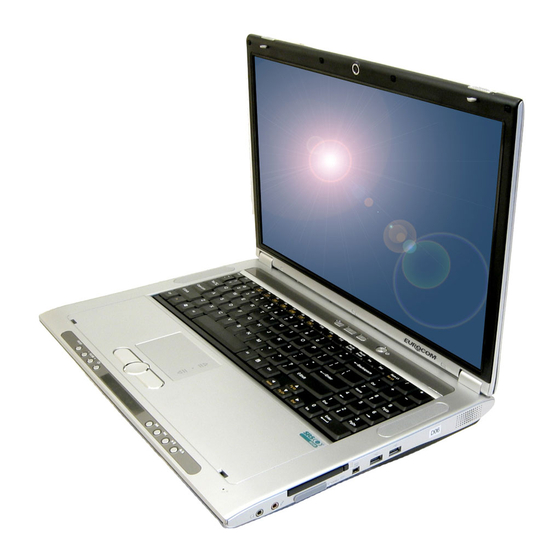
Introduction External Locator - Top View with LCD Panel Open Figure 1 Top View 1. Optional Built-In PC Camera 2. LCD 3. Hot Key Buttons 4. Power Button 5. Keyboard 6. TouchPad and Buttons 7. Audio "DJ" Controls 8. Built-In Microphone 9. -
Page 19: External Locator - Front View
Introduction External Locator - Front View Figure 2 Front View (Audio "DJ") 1. Audio "DJ" Power Button 2. Volume Down 3. Volume Up 4. Repeat 5. LED Display 6. Previous Track 7. Next Track 8. Play/Pause 9. Stop (Press Twice To Eject The CD/ DVD) 10. -
Page 20: External Locator - Rear View
Introduction External Locator - Rear View Figure 3 Rear View 1. Vent/Fan Intake/ Outlet 2. S/PDIF-Out Jack 3. Line-In Jack 4. 2 * USB 2.0 Ports 5. DVI-Out Port 6. TV Antenna Jack (Enabled With TV Tuner Only) 7. RJ-11 Phone Jack 8. -
Page 21: External Locator - Left & Right Side View
Introduction External Locator - Left & Right Side View Figure 4 Left Side View 1. Security Lock Slot 2. Speaker 3. Device Bay (for CD/DVD Device, or 2nd SATA Hard Disk, or 2nd Battery) Figure 5 Right Side View 1. Headphone-Out Jack 2. -
Page 22: External Locator - Bottom View
Introduction External Locator - Bottom View Figure 6 Bottom View 1. Vent/Fan Intake/ Outlet 2. Battery 3. Optical Device Release Latches 4. Video Card / HDD / RAM Bay Cover 5. Infrared & Consumer Infrared Transceiver 6. Sub Woofer Overheating To prevent your com- puter from overheating make... -
Page 23: Mainboard Overview - Top (Key Parts)
Introduction Mainboard Overview - Top (Key Parts) Figure 7 Mainboard Top Key Parts 1. LAN Transformer 2. Super I/O 3. Audio “DJ” 4. LAN 5. Flash BIOS ROM 6. New Card Assembly 7. 1394 and Card Reader 8. Clock Generator Mainboard Overview - Top (Key Parts) 1 - 11... -
Page 24: Mainboard Overview - Bottom (Key Parts)
Introduction Mainboard Overview - Bottom (Key Parts) Figure 8 Mainboard Bottom Key Parts 1. CPU Socket (no CPU installed) 2. 40-Pin VGA Socket 3. 160-Pin VGA Socket 4. Memory Slots DDR2 So-DIMM 5. Mini-PCI Socket (TV Tuner Card) 6. Mini-PCIe Socket (Wireless Lan Module) 7. -
Page 25: Mainboard Overview - Top (Connectors)
Introduction Mainboard Overview - Top (Connectors) Figure 9 Mainboard Top Connectors 1. MDC Connector 2. LED Cable Connector 3. CCD Cable Connector 4. Inverter Board Cable Connector 5. COM Port Cable Connector 6. Speaker-1 Cable Connector 7. Keyboard Cable Connector 8. -
Page 26: Mainboard Overview - Bottom (Connectors)
Introduction Mainboard Overview - Bottom (Connectors) Figure 10 Mainboard Bottom Connectors 1. S/PDIF-Out Jack 2. Line-In Jack 3. USB Port 4. DVI-Out Port 5. TV Antennna Jack 6. RJ-11 Jack 7. RJ-45 Jack 8. 7-Pin S-Video-Out Jack 9. DC-In Jack 10. -
Page 27: Disassembly
Disassembly 2: Disassembly Overview This chapter provides step-by-step instructions for disassembling the M570U/M575U series notebook’s parts and sub- systems. When it comes to reassembly, reverse the procedures (unless otherwise indicated). We suggest you completely review any procedure before you take the computer apart. Procedures such as upgrading/replacing the RAM, CD device and hard disk are included in the User’s Manual but are repeated here for your convenience. -
Page 28: Maintenance Tools
Disassembly NOTE: All disassembly procedures assume that the system is turned OFF, and disconnected from any power supply (the battery is removed too). Maintenance Tools The following tools are recommended when working on the notebook PC: • M3 Philips-head screwdriver •... -
Page 29: Maintenance Precautions
Disassembly Maintenance Precautions The following precautions are a reminder. To avoid personal injury or damage to the computer while performing a re- moval and/or replacement job, take the following precautions: Power Safety Warning 1. Don't drop it. Perform your repairs and/or upgrades on a stable surface. If the computer falls, the case and other Before you undertake components could be damaged. -
Page 30: Disassembly Steps
Disassembly Disassembly Steps The following table lists the disassembly steps, and on which page to find the related information. PLEASE PERFORM THE DISASSEMBLY STEPS IN THE ORDER INDICATED. To remove the Battery: To remove the TV Tuner Card: 1. Remove the battery page 2 - 5 1. -
Page 31: Removing The Battery
Disassembly Removing the Battery Figure 1 Battery Removal 1. Turn the computer off, and turn it over. 2. Slide latch towards the unlock symbol and hold it in place, and lift the battery up and out of the battery bay. a. -
Page 32: Removing The Hard Disk Drive
Disassembly Removing the Hard Disk Drive Figure 2 HDD Assembly The hard disk drive is mounted in a removable case and can be taken out to accommodate other 2.5" serial (SATA II) Removal hard disk drives with a height of 9.5mm (h). Follow your operating system’s installation instructions, and install all nec- essary drivers and utilities (as outlined in Chapter 4 of the User’s Manual) when setting up a new hard disk. - Page 33 Disassembly 5. Lift the hard disk module in the direction of the arrow 6. Remove the hard disk module Figure 3c) Figure 3 7. Remove screws and lift the HDD shielding plate up from the hard disk HDD Assembly 8. Reverse the process to install a new hard disk(s). Removal a.
-
Page 34: Removing The Optical (Cd/Dvd) Device
Disassembly Removing the Optical (CD/DVD) Device Figure 4 Optical Device 1. Turn off the computer, turn it over and remove the battery (page 2 - Removal 2. Slide latch towards the unlock symbol and hold it in place. 3. Slide latch (while still holding latch in place) in the direction indicated by the arrow in order to push the opti- a. -
Page 35: Removing The System Memory (Ram)
Disassembly Removing the System Memory (RAM) Figure 5 The computer has two memory sockets for 200 pin Small Outline Dual In-line Memory Modules (SO-DIMM) supporting RAM Module DDRII (DDR2) Up to 667 MHz. The main memory can be expanded up to 2GB. The SO-DIMM modules supported are Removal 256MB, 512MB and 1024MB DDRII Modules. -
Page 36: Removing The Processor
Disassembly Removing the Processor Figure 6 Processor Removal 1. Turn off the computer, turn it over, and remove the battery (page 2 - 5) and the component bay cover (page 2 - 2. The heat sink will be visible at point on the mainboard a. - Page 37 Disassembly 5. Turn the release latch towards the unlock symbol to release the CPU. Figure 7 6. Carefully (it may be hot) lift the CPU up and out of the socket (Figure 7e). Processor Removal 7. Reverse the process to install a new CPU. (cont’d) 8.
-
Page 38: Removing The Vga Card
Disassembly Removing the VGA Card Figure 8 VGA Card Removal 1. Turn off the computer, turn it over, and remove the battery (page 2 - 5), the component bay cover (page 2 - 6) and the CPU heat sink (page 2 - 10). -
Page 39: Removing The Wireless Lan Module
Disassembly Removing the Wireless LAN Module Figure 9 Wireless LAN 1. Turn off the computer, turn it over, and remove the battery (page 2 - 5) and the component bay cover (page 2 - Module Removal 2. The wireless LAN module will be visible at point on the mainboard. -
Page 40: Removing The Tv Tuner Card
Disassembly Removing the TV Tuner Card Figure 10 TV Tuner Card 1. Turn off the computer, turn it over, and remove the battery (page 2 - 5) and the component bay cover (page 2 - Removal 2. The TV Tuner card will be visible at point on the mainboard. -
Page 41: Removing The Bluetooth Module
Disassembly Removing the Bluetooth Module Figure 11 Bluetooth Module 1. Turn off the computer, turn it over, and remove the battery (page 2 - 5) and the component bay cover (page 2 - Removal 2. The Bluetooth module will be visible at point on the mainboard. -
Page 42: Removing The Keyboard
Disassembly Removing the Keyboard Figure 12 Keyboard Removal 1. Turn off the computer, and remove the battery (page 2 - 2. Press the four keyboard latches at the top of the keyboard to elevate the keyboard from its normal position (you a. -
Page 43: Removing The Modem
Disassembly Removing the Modem Figure 13 Modem Removal 1. Turn off the computer, turn it over and remove the battery (page 2 - 5), hard disk (page 2 - 6), optical device (page 8), RAM (page 2 - 9), CPU (page 2 - 10), VGA card (page 2 -... - Page 44 Disassembly 6. Carefully lift the top case (Figure 14e) up and off the computer. Figure 14 7. Remove screws from the modem and disconnect cable Modem Removal 8. Lift the modem Figure 14g up and off the computer. (cont’d) e. Lift the top case off the computer.
-
Page 45: Part Lists
Part Lists Appendix A:Part Lists This appendix breaks down the M570U/M575U series notebook’s construction into a series of illustrations. The compo- nent part numbers are indicated in the tables opposite the drawings. Note: This section indicates the manufacturer’s part numbers. Your organization may use a different system, so be sure to cross-check any relevant documentation. -
Page 46: Part List Illustration Location
Part Lists Part List Illustration Location The following table indicates where to find the appropriate part list illustration. Table A - 1 Part List Illustration Part M570U/M575U Location page A - 3 page A - 4 Bottom page A - 5 page A - 6 DVD-ROM Drive DVD-RW Drive... -
Page 47: Top
Part Lists Figure A - 1 無鉛 無鉛 無鉛 無鉛 無鉛 無鉛 無鉛 無鉛 漢保 無鉛 無鉛 無鉛 Top A - 3... -
Page 48: Bottom
Part Lists Bottom 無鉛 無鉛 無鉛 無鉛 無鉛 無鉛 無鉛 無鉛 同美 無鉛 Figure A - 2 無鉛 Bottom 無鉛 華力 無鉛 無鉛 無鉛 無鉛 (改善振動/噪音)無鉛 無鉛 (銅釘套管) 無鉛 無鉛 無鉛 無鉛 外 外 昆山 無鉛 外 (淺灰色) 無鉛 無鉛 無鉛... -
Page 49: Lcd
Part Lists Figure A - 3 無鉛 無鉛 無鉛 (墊高 0.5MM) 無鉛 無鉛 無鉛 無鉛 (墊高 0.5MM) 無鉛 無鉛 無鉛 華力 M570A 無鉛 華力 M570A 無鉛 華力 M570A 無鉛 無鉛 惠貿 無鉛 惠貿 無鉛 中性 無鉛 無鉛 華力 無鉛 無鉛 LCD A - 5... -
Page 50: Dvd-Rom Drive
Part Lists DVD-ROM Drive Figure A - 4 DVD-ROM Drive A - 6 DVD-ROM Drive... -
Page 51: Dvd-Rw Drive
Part Lists DVD-RW Drive Figure A - 5 DVD-RW Drive DVD-RW Drive A - 7... -
Page 52: Combo Drive
Part Lists Combo Drive Figure A - 6 Combo Drive A - 8 Combo Drive... -
Page 53: Hdd
Part Lists Figure A - 7 無鉛(變更螺絲孔直徑) HDD A - 9... -
Page 54: 2Nd Hdd
Part Lists 2nd HDD Figure A - 8 2nd HDD A - 10 2nd HDD... -
Page 55: Schematic Diagrams
Schematic Diagrams Appendix B:Schematic Diagrams This appendix has circuit diagrams of the M570U/M575U notebook’s PCB’s. The following table indicates where to find the appropriate schematic diagram. Diagram - Page Diagram - Page Diagram - Page Table B - 1 Schematic SYSYTEM BLOCK DIAGRAM - Page B - 2 ICH7-R 3/4 FWH - Page B - 16 +1.05VS, +2.5VS - Page B - 30... -
Page 56: Sysytem Block Diagram
Schematic Diagrams SYSYTEM BLOCK DIAGRAM M570U BLOCK DIAGRAM 1.+VCORE 1.+1.05VS,+2.5VS IMVP-6 VR CK-410M Yonah CPU 1.+1.8V,+1.5VS,+0.9VS 478uFCPGA VGA Daughter Card 1.CHARGER,DC IN VRAM DDR2 667MHz 667MHz 1.+VDD3,+VDD5 DDR 2 2.+3VH8 SO-DIMM 3.+3V,+5V,+3VS,+5VS 4.+5VCDROM,+3VCDROM Cailstoga 945PM PCI_E Sheet 1 of 40 1466 FCBGA TV OUT SYSYTEM BLOCK... -
Page 57: Clock Generator
Schematic Diagrams Clock Generator CLOCK GENERATOR +3VS HCB1608KF-121T25 C170 C171 C161 C172 C175 10UF 0.1UF 0.1UF 0.1UF Sheet 2 of 40 +3VS HCB1608KF-121T25 Clock Generator C155 C158 +3VS 10UF 0.1UF PLACE CRYSTAL 4.3K_1%/0402 WITHIN 500 MILS OF CK410M +3VS HCB1608KF-121T25 HCB1608KF-121T25 C134 C133... -
Page 58: Yonah 1/2
Schematic Diagrams YONAH 1/2 JSKT1A JSKT1B H_A#[31:3] H_D#[63:0] H_D#[63:0] [5] H_A#3 H_D#0 AA23 H_D#32 H_ADS# A[3]# ADS# D[0]# D[32]# H_A#4 H_D#1 AB24 H_D#33 A[4]# BNR# H_BNR# D[1]# D[33]# H_A#5 H_D#2 H_D#34 A[5]# BPRI# H_BPRI# [5] D[2]# D[34]# H_A#6 H_D#3 H_D#35 A[6]# D[3]# D[35]#... -
Page 59: Yonah 2/2
Schematic Diagrams YONAH 2/2 +VCORE +VCORE JSKT1D JSKT1C VSS[001] VSS[082] AB20 VCC[001] VCC[68] VSS[002] VSS[083] VCC[002] VCC[69] VSS[003] VSS[084] VCC[003] VCC[70] VSS[004] VSS[085] VCC[004] VCC[71] VSS[005] VSS[086] +VCORE AC12 VCC[005] VCC[72] VSS[006] VSS[087] AC13 VCC[006] VCC[73] VSS[007] VSS[088] AC15 VCC[007] VCC[74] VSS[008] VSS[089]... -
Page 60: Calistoga 1/5 Host
Schematic Diagrams Calistoga 1/5 Host U28A H_D#[63:0] H_A#[31:3] [3] H_D#0 H_A#3 H_D#_0 H_A#_3 H_D#1 H_A#4 H_D#_1 H_A#_4 H_D#2 H_A#5 H_D#_2 H_A#_5 H_D#3 H_A#6 H_D#_3 H_A#_6 H_D#4 H_A#7 H_D#_4 H_A#_7 H_D#5 H_A#8 H_D#_5 H_A#_8 H_D#6 H_A#9 H_D#_6 H_A#_9 H_D#7 H_A#10 H_D#_7 H_A#_10 H_D#8 H_A#11... -
Page 61: Calistoga 2/5
Schematic Diagrams Calistoga 2/5 U28B 24.9_1% +1.5VS AY35 U28C RSVD_1 SM_CK_0 M_CLK_DDR0 [10] PEG_COMP RSVD_2 SM_CK_1 M_CLK_DDR1 [10] L_BKLTCTL EXP_A_COMPI RSVD_3 SM_CK_2 M_CLK_DDR2 [11] L_BKLTEN EXP_A_COMPO AW40 M_CLK_DDR3 [11] RSVD_4 SM_CK_3 L_CLKCTLA AG11 PCIE_RXN0 RSVD_5 L_CLKCTLB EXP_A_RXN_0 AF11 AW35 PCIE_RXN1 RSVD_6 SM_CK#_0 M_CLK_DDR#0 [10]... -
Page 62: Calistoga 3/5 Ddr
Schematic Diagrams Calistoga 3/5 DDR U28D [10] M_A_DQ[63:0] M_A_DQ0 AJ35 AU12 U28E SA_DQ0 SA_BS_0 M_A_BS#0 [10] [11] M_B_DQ[63:0] M_A_DQ1 M_B_DQ0 AJ34 AV14 AK39 SA_BS_1 M_A_BS#1 [10] SA_DQ1 SB_DQ0 M_A_DQ2 AM31 BA20 M_B_DQ1 AJ37 AT24 M_A_BS#2 [10] M_B_BS#0 [11] SA_DQ2 SA_BS_2 SB_DQ1 SB_BS_0 M_A_DQ3... -
Page 63: Calistoga 4/5
Schematic Diagrams Calistoga 4/5 U28G 2900mA AA33 +1.05VS VCC_0 W 33 AU41 VCC_1 VCC_SM_0 AT41 U 28F U28I U 28J VCC_2 VCC_SM_1 AM41 AD 27 AC41 AK34 AT23 J 11 VCC_3 VCC_SM_2 VCC_NCTF0 VSS_0 VSS_97 VSS_180 VSS_273 AU40 AC 27 AE27 AA41 AG34... -
Page 64: Calistoga 5/5
Schematic Diagrams Calistoga 5/5 +1.5VS +1.5VS_PCIE +1.05VS HCB1608KF-121T25 1400mA C101 0/0402 C535 C537 C516 330UF/2.5V_V 10UF 10UF U28H 10UF 10UF 10UF 10UF 220UF/4V_V VCCSYNC AC14 VTT_0 +1.5VS_3GPLL AB14 VCC_TXLVDS0 VTT_1 VCC_TXLVDS1 VTT_2 HCB1608KF-121T25 +1.5VS VCC_TXLVDS2 VTT_3 C112 C106 C110 VTT_4 C558 C555 AJ41... -
Page 65: Dimm A
Schematic Diagrams DIMM A +VTT_MEM RESISTORS +0.9VS 16-56034-45A M_A_RAS# RN23 C233 0.1UF_X7R M_CS#0 4P2RX56_04 M_A_A0 RN22 C234 0.1UF_X7R JDIMM1A M_A_BS#1 4P2RX56_04 M_A_A[13:0] M_A_DQ[63:0] [7] M_A_A0 M_A_DQ0 M_A_A1 M_A_DQ1 M_ODT0 RN24 C231 0.1UF_X7R M_A_A2 M_A_DQ2 M_A_WE# 4P2RX56_04 M_A_A3 M_A_DQ3 M_A_A4 M_A_DQ4 M_A_A6 RN17 C235... -
Page 66: Dimm B
Schematic Diagrams DIMM B +VTT_MEM RESISTORS +0.9VS 16-56034-45A M_B_A7 R N36 C 203 0.1UF _X7R JD IMM2A M_B_A2 4P2RX56_04 M_B_A[13:0] M_B_D Q[63:0] [7] M_B_A0 M_B_D Q0 M_B_A1 M_B_D Q1 M_B_A13 R N35 C 200 0.1UF _X7R M_B_A2 M_B_D Q2 M_OD T2 4P2RX56_04 M_B_A3 M_B_D Q3... -
Page 67: Vga Card Connector
Schematic Diagrams VGA Card Connector CON2 DVI_HPD C415 0.1UF D VI_5VS JDVI1 TXM0 TXC M +5VS TXP0 TXC P CON 1 C ASE 1SS355 TXM2 TXM1 D AC1_HSYN C TMDS D ATA 2- TXP1 D AC1_VSY NC C482 TXP2 100K TMDS D ATA 2+ C483 0.1UF/50V/0603... -
Page 68: Ich7-R 1/4 Sata
Schematic Diagrams ICH7-R 1/4 SATA 2006/03/07 SCS751V C351 15PF +VDD3 +RTCVCC C358 R225 9/26 Ver 1.0B U35A 1UF/0603_X5R 32.768K LPC_AD[3:0] [15,26,27] R230 RTC_X1 LPC_AD0 RTXC1 LAD0 RTC_X2 C352 15PF LPC_AD1 RTCX2 LAD1 JCBAT1 1K/0402 SCS751V LPC_AD2 LAD2 R223 20K_1% RTC_RST# LPC_AD3 RTCRST# LAD3... -
Page 69: Ich7-R 2/4 (Pci, Usb
Schematic Diagrams ICH7-R 2/4 (PCI, USB) U35D [20] PCIE_RXN1_WLAN DMI_RXN0 [6] PERn1 DMI0RXN [20] PCIE_RXP1_WLAN PERp1 DMI0RXP DMI_RXP0 [6] C643 0.1UF [20] PCIE_TXN1_WLAN PETn1 DMI0TXN DMI_TXN0 [6] C644 0.1UF [20] PCIE_TXP1_WLAN PETp1 DMI0TXP DMI_TXP0 [6] Y 26 [19] PCIE_RXN2_NEW_CARD PERn2 DMI1RXN DMI_RXN1 [6] Y 25... -
Page 70: Ich7-R 3/4 Fwh
Schematic Diagrams ICH7-R 3/4 FWH RN49 +3VS 8P4RX 10K_04 U35C SM_CLK AF19 CLK_ICH14 R210 C350 *10PF SMBCLK (+3VS) GPIO21/SATA0GP SM_DATA AH18 SMBDATA (+3VS) GPIO19/SATA1GP LINKALERT# AH19 CLK_ICH48 R219 C361 *10PF LINKALERT# (+3VS) GPIO36/SATA2GP SMLINK0 AE19 SMLINK0 (+3VS) GPIO37/SATA3GP SMLINK1 SMLINK1 CLK_ICH14 CLK14 CLK_ICH14 [2]... -
Page 71: Ich7-R 4/4
Schematic Diagrams ICH7-R 4/4 +5VS +5VS U 35E +1.5VS_PC IE_ICH VSS[1] VSS[98] VSS[2] VSS[99] C 249 C 278 C 254 C 276 C 279 C 270 C 251 C 277 C 253 C 250 C 281 C 283 C 295 C 292 C 344 C 286... -
Page 72: Cd-Rom, Bt, Ccd, Usb2.0*2
Schematic Diagrams CD-ROM, BT, CCD, USB2.0*2 USBVCC0 +5VCDROM CD-ROM USB 2.0 TRACE WIDTH > 50mil HCB2012K-500T40 JCD1 R262 150K INT_CD_R INT_CD_L C395 [22,24] INT_CD_R INT_CD_L [22,24] CD_GND R261 270K 0.1UF 2006/03/10 JUSB1 CD_GND [22,24] CDD8 R358 33_0402 CRESETN 100UF/16V CRESETN [23] CDD9 CDD7 [14]... -
Page 73: Ti-7412/7402
Schematic Diagrams TI-7412/7402 R375 R374 +3VS 6.34K_1% 1394_XI C184 [14,20,21] AD[31:0] Crystal Place m ent 24.576MHz Cry stal must be place as close as CAD31/D10 possible to the Chip. Keep traces CAD30/D9 RSVD 1394_XO C186 all on one PCB lay er. CAD29/D1 RSVD CAD28/D8... -
Page 74: Card Reader & New Card
Schematic Diagrams Card Reader & New Card CARD READER C 671 0.1U JC R EAD ER 1 MS_SD 3_3V MS_BS/SD _CMD [18] MS_BS/SD_C MD MS_SD IO/SD_D AT0 Card Reader Power [18] MS_SD IO/SD _D AT0 MS_D ATA1/SD _DAT1 [18] MS_D ATA1/ SD _DAT1 MS_D ATA2/SD _DAT2 [18] MS_D ATA2/ SD _DAT2... -
Page 75: Mini Pci & Mini Card
Schematic Diagrams MINI PCI & MINI Card MINI CARD MINI PCI R530 10K/0402 +3VS LANMINIPCIE1 PIRQ#C R475 *0/0402 PCIE_WAKE# PIRQ#F R476 *0/0402 M1_IRQ [15,19] PCIE_WAKE# WAKE# 3.3V_0 +3VS BT_DAT R534 *0/0402 BT_DATA GND5 BT_CLK R532 *0/0402 +1.5VS BT_CHCLK 1.5V_0 WLAN_CLKREQ# CLKREQ# UIM_PWR CIR_RX... -
Page 76: Realtek Giga Lan
Schematic Diagrams Realtek GIGA LAN LAN_DVDD RLANVDD3 40 m il 100 m il RLANVCC1.3 BK2125HS121 JLAN1 BK2125HS121 JMODEM1 HK2125 R10J-T C781 C782 C783 C784 C785 C786 C787 2006/03/07 C788 C789 RING 10U/6.3V 0.1U 0.1U V_DAC_R HK2125 R10J-T 10U/6.3V 0.1U 0.1U 0.1U 0.1U 10U/6.3V... -
Page 77: Ac97, Fan & Led Board Connector
Schematic Diagrams AC97, FAN & LED Board Connector R413 10K/0402 +VDD5 R409 10K/0402 2N7002 ALC202 ALC655 2N7002 C615 AC97_VDD SPDIF/SURRB-L [24] SPDIF/SURRB-L +3VCDROM R474 C686 *1UF C680 C667 C685 0.1UF 0.1UF Vaux DCVOL C681 1000PF VRDA AVDD VRAD AC97_VDD ALC202 AVDD AFILT2 C691... -
Page 78: Audio Dj
Schematic Diagrams Audio DJ 2006/03/07 +3VCDROM +5VCDROM +3VCDROM VCC5 VCC5 C_ACRST# R163 10K/0402 JADJ1 BBLED_STB F_DD6 R178 10K/0402 BBLED_CLK F_DD7 R168 10K/0402 BlueBirdVL [27] BBLED_DATA C245 C284 SD_DAT2 R135 10K/0402 [27] PLAY_PAUSE C265 C260 C298 C274 0.1UF 0.1UF BB_WP R177 *10K/0402 PLAY_PAUSE [27] STOP_EJECT... -
Page 79: Azalia Codec & Amp
Schematic Diagrams Azalia CODEC & AMP 2006/03/08 10UF/10V +3VS +5VS BK2 12 5HS121 (08 05 ) BK2 12 5HS1 21 (080 5) C710 C736 C716 JINTMIC1 C728 C719 C737 0.1UF 10UF/10V 2006/03/08 10UF/10V 0.1UF 0.1UF C169 CON2_MIC 330PF LFEOUT [17] INTMICO [17] C721 LFEOUT... -
Page 80: Pre Amp & Sub-Woofer
Schematic Diagrams Pre Amp & Sub-Woofer R237 C371 10UF/6.3V [22] AC97_OUT_R C372 10UF/6.3V [24] FRONT-R R238 C374 10UF/6.3V [22] AC97_OUT_L C373 10UF/6.3V [24] FRONT-L R519 R520 6.8K R236 R235 WOWO_VDD C741 C370 R242 2.2K C740 0.1UF 0.1UF 10UF/6.3V 5.1K R243 2.2K C739 0.1UF... -
Page 81: Super I/O, Ir & Cir & Tpm
Schematic Diagrams Super I/O, IR & CIR & TPM 2006/03/08 +3VS C273 C272 C 287 C 319 10UF/10V 0.1U F 0.1U F 0.1UF +3VS C306 C310 0.1U F 1U F U 13 COM PORT LPC _AD0 C 308 [13,15,27] LPC _AD 0 LAD 0 LPC _AD1 JC OM1... - Page 82 Schematic Diagrams H8_BATTEMP_A C622 +3VH8 +3VH8 +3VH8 +VDD5 H8_BATVOLT_A C623 HC B2012K-121T30 KB-SI0 KB-SI1 KB-SI7 +3VH8 H8_BATTEMP_B C624 KB-SI2 KB-SI6 KB-SI3 KB-SI5 H8_BATVOLT_B C625 KB-SI4 LID_RSU M# C661 C230 C242 C627 C628 C629 C630 C213 H8_CURSEN C626 0.1UF 0.1UF 0.1UF 0.1UF 0.
-
Page 83: Vcore
Schematic Diagrams +VCORE +5VS OPEN_10mil PM_PSI# [3,13] H_DPRSTP# +5VS +VDD5 H_VID6 PC36 H_VID5 H_VID4 OPEN_10mil H_VID3 H_VID2 H_VID1 +3VS +VDD3 H_VID0 PR31 +5VS +3VS PR30 PC31 PR36 4.7UF/25V/0805 4.7UF/25V/0805 IRF7821TRPBF 4.7UF/25V/0805 4.7UF/25V/0805 PR135 PR33 PC34 PC56 PC57 PC58 PC55 PC54 RB751V 4.7UF_0805 0.1UF/0603... -
Page 84: Vs, +2.5Vs
Schematic Diagrams +1.05VS, +2.5VS PR12 +VD D5 VIN1 PC154 PC142 PC155 PC141 PR15 10uF_25V/1206 10uF_25V/1206 10uF _25V/1206 10uF_25V/1206 PD25 PR11 PR113 270K RB751V PQ27 RQA 13 0N03 EN /PSV 1.05V PC11 0.1UF/0603 +1.05VS PQ31 2N7002 PC148 PR105 2 2.5UH 8A(5A) PR 13 100K 0.1UF/0603... -
Page 85: V, 0.9V, +1.5Vs
Schematic Diagrams +1.8V, 0.9V, +1.5VS FOR EMI +VD D 5 PC 120 0.1u(X7R)/ 0603 +0.9VS +1. 8V PU 7 1.8_SD # PD 23 VDD QEN OC D DQ PR 95 7. 15K_1% PC 112 C 366 C258 C 143 C 337 R B751V 0.1U /0603 0.01UF... -
Page 86: Vdd3, +Vdd5
Schematic Diagrams +VDD3, +VDD5 FOR EMI +5VS VI N C 357 C732 C687 0.01UF 0.01UF 0.01UF/50V/0603 0.01UF/50V/0603 0.01UF/50V/0603 VI N 0. 01UF/50V/ 0603 0.01UF/50V/0603 VIN1 +VDD5 +3VS PR91 C 181 C365 C177 C377 C727 C569 C620 PC190 10U_0805 0.01UF 0.01UF 0.01UF 0.01UF 0.01UF... -
Page 87: Charger, Dc-In
Schematic Diagrams CHARGER, DC-IN VA++ BAT_A 10UF /25V/1206 10UF /25V/1206 PQ29 AM4835P PD26 JAC1 PF 1 * 7A 10UF/25V/1206 10UF/25V/1206 20m _2512 15uH PR18 25m_2512 AM4835P PF 3 0 .1 UF/5 0 V (0 8 05 ) 0.1 UF /5 0 V (08 0 5) VA++ PR14 1 0UF/2 5V /1 20 6... -
Page 88: Button Board
Schematic Diagrams Button Board B+5V B+5V *680 B+3VH8 BJLED1 BDGND BPWRON_LED *2.7K POWER POWER BPWRBTN# BLID_RSUM# BUTTON BUTTON LED_1206 *LED_1206 BWEB#0 BLID_RSUM# BWEB#1 BWEB#2 M570A M560A B+5V 0.01UF *TLE_4917DS B+3VH8 BCON10 0.1UF 0.1UF SWTICH BDGND BDGND BPWRON_LED BPWRON_LED M560A Sheet 33 of 40 BDGND Button Board DTC114EUA... -
Page 89: Card Reader Board
Schematic Diagrams Card Reader Board FOR M560U CJCREADER2 CMS_SD3_3V CMS_BS/SD_CMD CMS_SDIO/SD_DAT0 CMS_DATA1/SD_DAT1 CMS_DATA2/SD_DAT2 CJREADER1 CMS_DATA3/SD_DAT3 CSD_WP CMS_CD# SD-WP-SW CMS_DATA1/SD_DAT1 CSD_CD# SD-DATA1 CMS_SDIO/SD_DAT0 CMS_CLK/SD_CLK SD-DATA0 CSD_WP SD-GND1 MS-GND1 CMS_BS/SD_CMD MS-BS CMS_CLK/SD_CLK SD-CLK CMS_DATA1/SD_DAT1 MS-DATA1 CMS_SD3_3V CMS_SDIO/SD_DAT0 MS-DATA0 CDGND *CON14 CMS_SD3_3V SD-VCC CMS_DATA2/SD_DAT2 MS-DATA2 SD-GND2... -
Page 90: Usb & 1394 Board - M560U
Schematic Diagrams USB & 1394 Board - M560U UGND 0.1UF UJUSB2 UUSBOVCC1 UUSBN1 DATA_L GND4 GND3 UUSBP1 DATA_H UJEXT1 PWC1206ST161T UUSBOVCC1 UUSBN1 UUSBP1 Note: Close to USB CONN. UUSBOVCC6 UGND UUSBN6 UUSBP6 UGND U1394A0P U1394A0N U1394B0P U1394B0N UGND USPKOUTR UBTL# USPKOUTL 0.1UF ULFEOUT... -
Page 91: Usb & 1394 Board - M570U
Schematic Diagrams USB & 1394 Board - M570U VJEXT1 VUSBOVCC1 0.1UF VUSBN1 VGND VUSBP1 VJUSB1 VUSBOVCC6 VUSBOVCC1 VUSBN6 VUSBP6 VUSBN1 DATA_L GND4 GND3 V1394A0P VUSBP1 DATA_H V1394A0N PWC1206ST161T V1394B0P 2006/03/10 V1394B0N VSPKOUTR VBTL# VSPKOUTL VGND VLFEOUT VINTMICO VGND VMICO VCON20 0.1UF VGND VGND... -
Page 92: Com Port Board
Schematic Diagrams COM Port Board EJCOM1 ELP2 EJCOM2 8P4LXBLA3216A221SG4 EDCD# ERING# ERXD EDTR# ETXD ECTS# EDTR# ETXD EDSR# ERTS# ERTS# ERXD ECTS# EDSR# ERING# EDCD# Sheet 37 of 40 8P4LXBLA3216A221SG4 COM Port Board ECOM1_DB9 ECON9 ELP1 ECP1 ECP2 8P4CX180PF EDGND 8P4CX180PF EDGND EDGND... -
Page 93: Audio Dj Board
Schematic Diagrams Audio “DJ” Board 2006/03/07 AJADJ1 AVOLUM_UP ABBLED_STB ABBLED_CLK ABBLED_DATA APLAY_PAUSE AVCC_LED *100U ASTOP_EJECT APDLED# AC23 AC24 AC25 AC26 A+5VCDROM AVOLUM_DOWN AGR1 AVOLUM_UP 47PF 47PF 47PF 47PF AGR2 ACDPWRBTN# AGR3 0.1UF/0603 A_AH8LED_CLK1 AGR4 A_AH8LED_DATA AGR5 ADGND A_AH8LED_CLK2 AGR6 ABBLED_DATA AGR1 ABBLED_STB ADGND... -
Page 94: Click Board
Schematic Diagrams Click Board M560A M570A M560A SYNAPTICS SYNAPTICS ELANTECH ELANTECH GR10 GR20 GR20 GTP_R_56 GR10 GJTP2 G+5VS G+5VS GR20 GR19 GR19 G+5VS GR19 GJTP1 GTP_DATA GR18 GR16 GR18 GR18 GTP_L_56 GTP_CLK GTP_CLK GR17 GR15 GR17 GR17 GTP_DATA GTP_CLK GR16 GR14 GTP_R_57 GTP_R_56... -
Page 95: Second Sata Hdd Board
Schematic Diagrams Second SATA HDD Board MJSATA1 MSATATXP1 MSATATXN1 M+3VS MSATARXN1 MSATARXP1 MCON1 0.1UF 10UF/0805 M+3VS MSATARXN1 MSATARXP1 MGND MGND MSATATXN1 M+5VS Sheet 40 of 40 MSATATXP1 M+5VS Second SATA HDD Board GND1 GND2 CON20 0.1UF 0.1UF 10UF/0805 *100UF/6.3V/D MGND MGND C16656-12204-L MGND... - Page 96 Schematic Diagrams B - 42...
Need help?
Do you have a question about the M570U and is the answer not in the manual?
Questions and answers