Table of Contents
Advertisement
Quick Links
Advertisement
Table of Contents

Related Manuals for EUROCOM M375E


Summary of Contents for EUROCOM M375E
- Page 1 All manuals and user guides at all-guides.com...
- Page 2 All manuals and user guides at all-guides.com...
- Page 3 All manuals and user guides at all-guides.com Preface Notebook Computer M375E Service Manual...
- Page 4 All manuals and user guides at all-guides.com Preface Notice The company reserves the right to revise this publication or to change its contents without notice. Information contained herein is for reference only and does not constitute a commitment on the part of the manufacturer or any subsequent ven- dor.
- Page 5 This manual is intended for service personnel who have completed sufficient training to undertake the maintenance and inspection of personal computers. It is organized to allow you to look up basic information for servicing and/or upgrading components of the M375E series notebook PC.
- Page 6 All manuals and user guides at all-guides.com Preface IMPORTANT SAFETY INSTRUCTIONS When using your telephone equipment, basic safety precautions should always be followed to reduce the risk of fire, elec- tric shock and injury to persons, including the following: 1. Do not use this product near water, for example near a bath tub, wash bowl, kitchen sink or laundry tub, in a wet basement or near a swimming pool.
- Page 7 All manuals and user guides at all-guides.com Preface Instructions for Care and Operation The notebook computer is quite rugged, but it can be damaged. To prevent this, follow these suggestions: Don’t drop it, or expose it to shock. If the computer falls, the case and the components could be damaged. Do not expose the computer Do not place it on an unstable Do not place anything heavy...
- Page 8 All manuals and user guides at all-guides.com Preface 4. Avoid interference. Keep the computer away from high capacity transformers, electric motors, and other strong mag- netic fields. These can hinder proper performance and damage your data. 5. Take care when using peripheral devices. Use only approved brands of Unplug the power cord before peripherals.
- Page 9 All manuals and user guides at all-guides.com Preface Battery Precautions • Only use batteries designed for this computer. The wrong battery type may explode, leak or damage the computer. • Recharge the batteries using the notebook’s system. Incorrect recharging may make the battery explode. •...
- Page 10 All manuals and user guides at all-guides.com Preface Related Documents You may also need to consult the following manual for additional information: User’s Manual on CD This describes the notebook PC’s features and the procedures for operating the computer and its ROM-based setup pro- gram.
-
Page 11: Table Of Contents
Introduction ..........1-1 LCD (M375E) ................A-5 Card Reader (M375E) ..............A-6 Overview ..................1-1 CD-ROM Drive - QSI-TEAC (M375E) ........A-7 System Specifications ..............1-2 CD-RW Drive - TEAC (M375E) ........... A-8 External Locator - Top View with LCD Panel Open ......1-5 Combo Drive - TEAC (M375E) ............ - Page 12 All manuals and user guides at all-guides.com Preface TI1394 (TSB43AB21) ..............B-24 M10 AGP/PCI/Power ..............B-25 M10 MEM I/F-A ................B-26 M10 MEM I/F-B ................B-27 M10 VGA Connector ..............B-28 Panel CON ..................B-29 VGA DDR DRAM Termination ..........B-30 Audio Out &...
-
Page 13: Introduction
1: Introduction Overview This manual covers the information you need to service or upgrade the M375E series notebook computer. Information about operating the computer (e.g. getting started, and the Setup utility) is in the User’s Manual. Information about driv- ers (e.g. VGA & audio) is also found in User’s Manual. That manual is shipped with the computer. -
Page 14: System Specifications
All manuals and user guides at all-guides.com Introduction System Specifications Feature Specification µ Processor Types Intel® Pentium® M Processor (478-pin) Micro- 0.13) 0.13 Micron Process Technology, µ )FCPGA Package 1MB On-die L2 Cache & 400MHz Front Side Bus - 1.3/ 1.4/ 1.5/ 1.6/ 1.7 GH µ... - Page 15 All manuals and user guides at all-guides.com Introduction Feature Specification Keyboard, Pointing Full Size Winkey Keyboard with Numeric Keypad Built-In TouchPad (Scroll Functionality Included) Device & Buttons PCMCIA One Type II PCMCIA 3.3V/5V Socket Interface & Three USB 2.0/1.1 Ports One New 4-in-1 built-in Card Reader Communication One Mini IEEE1394 Ports...
- Page 16 All manuals and user guides at all-guides.com Introduction Feature Specification Optional CD-RW Drive Module Mini PCI Intel PRO/ Wireless 2100 WLAN Module Combo Drive Module Mini PCI Intel PRO / Wireless 2200BG WLAN Module DVD-ROM Drive Module Bluetooth 1.1 + MDC Module DVD-RW Drive Module USB VGA Camera Module DVD-Dual Drive Module...
-
Page 17: External Locator - Top View With Lcd Panel Open
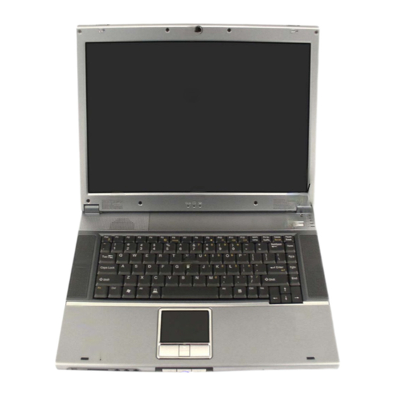
All manuals and user guides at all-guides.com Introduction External Locator - Top View with LCD Panel Open Figure 1 Top View 1. Optional Built-In PC Camera 2. LCD 3. LED Power & Communication Indicators 4. Speakers 5. Close Cover Switch 6. -
Page 18: External Locator - Front & Left Side Views
All manuals and user guides at all-guides.com Introduction External Locator - Front & Left Side Views Figure 2 Front View 1. LCD Latches 2. Mini-IEEE 1394 Port 3. 3-in-1 Card Reader 4 5 6 4. S/P DIF Out Port 5. Microphone-In Jack 6. -
Page 19: External Locator - Right Side & Rear Views
All manuals and user guides at all-guides.com Introduction External Locator - Right Side & Rear Views Figure 4 Right Side View 1. USB 2.0/1.1 Port 2. Serial Port 3. Optical Device 4. DC-In Jack Figure 5 Rear View 1. Security Lock Slot External Locator - Right Side &... -
Page 20: External Locator - Bottom View
All manuals and user guides at all-guides.com Introduction External Locator - Bottom View Figure 6 Bottom View 1. Vent/Fan Intakes 2. Battery 3. CPU Bay Cover 4. RAM Module Cover 5. Hard Disk, WLAN & Bluetooth Module Cover 6. Optical Device Removal Cover Overheating To prevent your com-... -
Page 21: Mainboard Overview - Top (Key Parts)
All manuals and user guides at all-guides.com Introduction Mainboard Overview - Top (Key Parts) Figure 7 Mainboard Top Key Parts 1. PC Card Assembly 2. Northbridge - Intel 855PM 3. Southbridge - 82801DBM 4. H8 5. LPC Super I/O NS PC87383 6. -
Page 22: Mainboard Overview - Bottom (Key Parts)
All manuals and user guides at all-guides.com Introduction Mainboard Overview - Bottom (Key Parts) Figure 8 Mainboard Bottom Key Parts 1. CPU Socket (no CPU installed) 2. Memory Slots (no memory installed) 3. ATI Mobility Radeon 9600 Pro 4. Flash BIOS ROM 5. -
Page 23: Mainboard Overview - Top (Connectors)
All manuals and user guides at all-guides.com Introduction Mainboard Overview - Top (Connectors) Figure 9 Mainboard Top Connectors 1. Inverter Cable Connector (CN2) 2. Speaker Cable Connector (JSPK1) 3. Fan Cable Connector (JFAN1) 4. Keyboard Cable Connector (JKB1) 5. TouchPad Cable Connector (JTP1) 6. -
Page 24: Mainboard Overview - Bottom (Connectors)
All manuals and user guides at all-guides.com Introduction Mainboard Overview - Bottom (Connectors) Figure 10 Mainboard Bottom Connectors 1. Battery Connector (JBATT1) 2. CD-ROM Connector (J3) 3. Fan Cable Connector (JFAN2) 4. Hard Disk Connector (JHDD1) 5. Mini-PCI (Wireless Lan Module) Connector (JMINIPCI1) -
Page 25: Disassembly
2: Disassembly Overview This chapter provides step-by-step instructions for disassembling the M375E series notebook’s parts and subsystems. When it comes to reassembly, reverse the procedures (unless otherwise indicated). We suggest you completely review any procedure before you take the computer apart. -
Page 26: Maintenance Tools
All manuals and user guides at all-guides.com Disassembly NOTE: All disassembly procedures assume that the system is turned OFF, and disconnected from any power supply (the battery is removed too). Maintenance Tools The following tools are recommended when working on the notebook PC: •... -
Page 27: Maintenance Precautions
All manuals and user guides at all-guides.com Disassembly Maintenance Precautions The following precautions are a reminder. To avoid personal injury or damage to the computer while performing a re- moval and/or replacement job, take the following precautions: Power Safety Warning 1. -
Page 28: Disassembly Steps
All manuals and user guides at all-guides.com Disassembly Disassembly Steps The following table lists the disassembly steps, and on which page to find the related information. PLEASE PERFORM THE DISASSEMBLY STEPS IN THE ORDER INDICATED. To remove the Battery: To remove the Processor: 1. -
Page 29: Removing The Battery
All manuals and user guides at all-guides.com Disassembly Removing the Battery 1. Turn the computer off, and turn it over. 2. Locate the battery bay at point (Figure 1a). Figure 1 3. Slide the battery lock in the direction of the arrow (towards the unlock symbol ), and hold it in place (as Battery Removal shown in... -
Page 30: Removing The Hard Disk Drive
All manuals and user guides at all-guides.com Disassembly Removing the Hard Disk Drive The hard disk drive is mounted in a removable case and can be taken out to accommodate other 2.5" IDE hard disk drives Figure 2 with a height of 9.5mm (h). Follow your operating system’s installation instructions, and install all necessary drivers and HDD Assembly utilities (as outlined in Chapter 4 of the User’s Manual) when setting up a new hard disk. - Page 31 All manuals and user guides at all-guides.com Disassembly 4. Slide the hard disk assembly in the direction of the arrow Figure 3 5. Carefully lift the hard disk assembly up out off the computer. HDD Assembly 6. Remove screws in order to separate the cover from the hard disk (Figure 3c).
-
Page 32: Removing The Modem
All manuals and user guides at all-guides.com Disassembly Removing the Modem Figure 4 Modem Removal 1. Turn off the computer, remove the battery (page 2 - 5) and the HDD bay cover (page 2 - 2. Remove screws Figure 4a carefully separate the modem from the connector and disconnect cables a. -
Page 33: Removing The Wireless Lan
All manuals and user guides at all-guides.com Disassembly Removing the Wireless LAN Figure 5 Wireless LAN 1. Turn off the computer, remove the battery (page 2 - 5) and the HDD bay cover (page 2 - Removal 2. Carefully disconnect cable , then gently pull the two release latches ( ) on the sides of the module socket. -
Page 34: Removing The System Memory (Ram)
All manuals and user guides at all-guides.com Disassembly Removing the System Memory (RAM) Figure 6 The computer has two memory sockets for 200 pin Small Outline Dual In-line Memory Modules (SO-DIMM) supporting Removing/ DDR 266/333MHz. The main memory can be expanded up to 2GB. The SO-DIMM modules supported are 128Mb, Installing a RAM 256Mb, and 512Mb. - Page 35 All manuals and user guides at all-guides.com Disassembly 6. Pull the latches to release the second module if necessary. 7. Insert a new module holding it at about a 30° angle and fit the connectors firmly into the memory slot. 8.
-
Page 36: Removing The Optical (Cd/Dvd) Device
All manuals and user guides at all-guides.com Disassembly Removing the Optical (CD/DVD) Device 1. Turn off the computer, and remove the battery (page 2 - Figure 7 2. Remove screw at point (Figure 7a) and carefully lift up the optical device screw cover (Figure 7b). -
Page 37: Removing The Processor
All manuals and user guides at all-guides.com Disassembly Removing the Processor Figure 8 1. Turn off the computer, and remove the battery (page 2 - Processor Removal 2. Remove screws from the CPU cover 3. Carefully lift up the CPU cover off the computer. - Page 38 All manuals and user guides at all-guides.com Disassembly 6. Turn the release latch towards the unlock symbol , to release the CPU (Figure 9a). 7. Carefully (it may be hot) lift the CPU up out of the socket (Figure 9b). 8.
-
Page 39: Removing The Keyboard
All manuals and user guides at all-guides.com Disassembly Removing the Keyboard 1. Turn off the computer, and remove the battery (page 2 - 2. Press the three keyboard latches at the top of the keyboard to elevate the keyboard from its normal position (you Figure 10 may need to use a small screwdriver to do this). - Page 40 All manuals and user guides at all-guides.com Disassembly 2 - 16...
-
Page 41: Part Lists
Part Lists Appendix A:Part Lists This appendix breaks down the M375E series notebook’s construction into a series of illustrations. The component part numbers are indicated in the tables opposite the drawings. Note: This section indicates the manufacturer’s part numbers. Your organization may use a different system, so be sure to cross-check any relevant documentation. -
Page 42: Part List Illustration Location
Part Lists Part List Illustration Location The following table indicates where to find the appropriate part list illustration. Table 1 - 1 Part List Illustration Part M375E Location page A - 3 page A - 4 Bottom page A - 5... -
Page 43: Top (M375E
All manuals and user guides at all-guides.com Part Lists Top (M375E) Figure 1 Top (M375E) Top (M375E) A - 3... -
Page 44: Bottom (M375E
All manuals and user guides at all-guides.com Part Lists Bottom (M375E) Figure 2 Bottom (M375E) 藍灰色 無鉛 A - 4 Bottom (M375E) -
Page 45: Lcd (M375E
All manuals and user guides at all-guides.com Part Lists LCD (M375E) Figure 3 LCD (M375E) LCD (M375E) A - 5... - Page 46 All manuals and user guides at all-guides.com Part Lists CD-ROM Drive - SAMSUNG (M375E) Figure 4 CD-ROM Drive - SAMSUNG (M375E) A - 6 CD-ROM Drive - SAMSUNG (M375E)
-
Page 47: Cd-Rw Drive - Teac (M375E
All manuals and user guides at all-guides.com Part Lists CD-RW Drive - TEAC (M375E) Figure 5 CD-RW Drive - TEAC (M375E) CD-RW Drive - TEAC (M375E) A - 7... - Page 48 All manuals and user guides at all-guides.com Part Lists Combo Drive - SAMSUNG (M375E) Figure 6 Combo Drive - SAMSUNG (M375E) A - 8 Combo Drive - SAMSUNG (M375E)
- Page 49 All manuals and user guides at all-guides.com Part Lists DVD-Dual Drive - PIONEER (M375E) Figure 7 DVD-Dual Drive - PIONEER (M375E) DVD-Dual Drive - PIONEER (M375E) A - 9...
- Page 50 All manuals and user guides at all-guides.com Part Lists DVD-ROM Drive - TOSHIBA (M375E) Figure 8 DVD-ROM Drive - TOSHIBA (M375E) A - 10 DVD-ROM Drive - TOSHIBA (M375E)
-
Page 51: Dvd-Rw Drive - Toshiba (M375E
All manuals and user guides at all-guides.com Part Lists DVD-RW Drive - TOSHIBA (M375E) Figure 9 DVD-RW Drive - TOSHIBA (M375E) DVD-RW Drive - TOSHIBA (M375E) A - 11... - Page 52 All manuals and user guides at all-guides.com Part Lists A - 12...
-
Page 53: Schematic Diagrams
All manuals and user guides at all-guides.com Schematic Diagrams Appendix B:Schematic Diagrams This appendix has circuit diagrams of the M375E notebook’s PCB’s. The following table indicates where to find the ap- propriate schematic diagram. Table 1 Diagram - Page Diagram - Page... - Page 54 All manuals and user guides at all-guides.com Schematic Diagrams System Block Diagram MEMORY TERMINATIONS SHEET 9 DC/DC DDR SDRAM SOCKET +VCCP(1.05V),+1.2VS V_CORE,+VDD3,+VDD5 Banias +12V,+1.25VS,+2.5V CORE ACIN;POWER Processor-M BUTTON POEWR SHEET 33,34,35 TV OUT (VCORE) SHEET 36,31 479 uFCPGA SO-DIMM0 SO-DIMM1 SHEET 28 PG3,4 SHEET 8...
- Page 55 All manuals and user guides at all-guides.com Schematic Diagrams Socket 479 - 1 of 2 11,12,13,15,17,20,22,23,24,31,32,34,35 +3VS +3VS 8,10,11,12,13,15,16,17,18,20,21,25,27,28,29,31,32,33,35,37 +3VH8 +3VH8 11,20,31,32,34,37 +VCCP +VCCP 4,6,7,12,13,33 H_D#[63:0] H_D#[63:0] 6 +VCCP U35B H_REQ#[4:0] U35A H_D#0 H_D#32 D32# PM_THRMTRIP# R285 H_D#1 AA24 H_D#33 H_A20M# 11 A20M# D33#...
- Page 56 All manuals and user guides at all-guides.com Schematic Diagrams Socket 479 - 2 of 2 +1.8VS_PROC +1.8VS +1.5VS R315 0(0805) V_CORE V_CORE V_CORE +VCCP +VCCP 3,6,7,12,13,33 R317 *0(0805) +1.8VS +1.8VS 6,7,11,13,23,25,27,28,32 +1.5VS +1.5VS 5,7,11,13,25,32 +1.8VS FOR BANIAS CPU +2.5V +2.5V 5,7,8,11,34,35 U35C +1.5VS FOR DOTHAN CPU...
- Page 57 All manuals and user guides at all-guides.com Schematic Diagrams 855PM MCH-1 +2.5V +2.5V +2.5V 7,8,11,34,35 +1.5VS +1.5VS 4,7,11,13,25,32 AGP_AD[0..31] +1.25VS UB1E AGP_AD[0..31] UB1B +1.25VS 9,26,27,30,35 M_DATA[63:0] M_DQS[8:0] 9 M_DATA0 M_DQS0 AGP_AD0 Z0503 R324 SDQ0 SDQS0 G_AD0 RSVD AGP_AD1 Z0504 M_DATA1 M_DQS1 10K(0402) SDQ1...
-
Page 58: 855Pm Mch-2
All manuals and user guides at all-guides.com Schematic Diagrams 855PM MCH-2 +VCCP +VCCP 3,4,7,12,13,33 +1.8VS +1.8VS 4,7,11,13,23,25,27,28,32 UB1A I855PM H_A#[31:3] H_D#[63:0] 3 H_A#3 H_D#0 HA3# HD0# H_A#4 H_D#1 HA4# HD1# H_A#5 H_D#2 HA5# HD2# H_A#6 H_D#3 HA6# HD3# H_A#7 H_D#4 HA7# HD4# H_A#8... -
Page 59: 855Pm Mch-3
All manuals and user guides at all-guides.com Schematic Diagrams 855PM MCH-3 +VCCP UB1C +VCCP 3,4,6,12,13,33 +1.2VS +1.5VS +1.2VS VSS0 VSS84 +1.2VS 11,25,33 +1.5VS 4,5,11,13,25,32 AB11 DEL C554(150U) +2.5V +2.5V 5,8,11,34,35 VSS1 VSS85 AD12 +1.8VS +1.5VS +1.8VS 4,6,11,13,23,25,27,28,32 VSS2 VSS86 AF11 L100 *L_0805(159) VSS3... -
Page 60: Ddram
All manuals and user guides at all-guides.com Schematic Diagrams DDRAM +2.5V +2.5V +3VS +3VS 3,10,11,12,13,15,16,17,18,20,21,25,27,28,29,31,32,33,35,37 +2.5V +2.5V 5,7,11,34,35 13,14,15,18,20,23,31,33,34,35 M_DATA_R_[63:0] M_DATA_R_[63:0] 9 DDR SO-DIMM_R DDR SO-DIMM M_AA_FR_0 M_DATA_R_63 M_AA0 M_AA_FR_0 M_AA0 M_AA_FR_1 M_DATA_R_62 M_AA1 M_AA_FR_1 M_AA1 M_AA_FR_2 M_DATA_R_61 M_AA2 M_AA_FR_2 M_AA2 M_AA_FR_3 M_DATA_R_60... -
Page 61: Ddr Termination
All manuals and user guides at all-guides.com Schematic Diagrams DDR Termination +1.25VS +1.25VS 5,26,27,30,35 +1.25VS +1.25VS RP19 10P8RX56 10P8RX56 M_DATA_R_50 M_CKE3 Z0901 M_DATA_R_51 M_AA3 M_DATA_R_48 M_AA3 M_AA5 M_DATA_R_49 +1.25VS M_AA5 M_AA1 M_DATA_R_52 M_AA1 M_AA12 RP20 8P4RX22 M_AA_FR_12 M_AA7 M_DATA_R_53 M_AA12 M_AA_FR_12 8 M_AA7 M_DQS_R6... -
Page 62: Clock Generator
All manuals and user guides at all-guides.com Schematic Diagrams Clock Generator +3VS +3VS 3,8,11,12,13,15,16,17,18,20,21,25,27,28,29,31,32,33,35,37 FREQUENCY SETUP TABLE VDDCPU +3VS (FS2) (FS1) (FS0) 3V66 66MHz OUT (MHz) (MHz) (MHz) (MHz) L_0805(159) C578 C580 66.66 66.66 66.66 33.33 10U(0805)/6.3V .1u(0402) 66.66 66.66 33.33 66.66 66.66... -
Page 63: Ich4-1 (1
All manuals and user guides at all-guides.com Schematic Diagrams ICH4-1 (1 of 3) R214 10K(0402) +1.2VS 取代原先 之線路 +1.2VS 7,25,33 +1.5VS +1.5VS 4,5,7,13,25,32 +3VH8 PCIRST# +3VH8 3,20,31,32,34,37 15,17,20,22,24,32 PRST# +3VS +3VS 3,8,10,12,13,15,16,17,18,20,21,25,27,28,29,31,32,33,35,37 +5VS +5VS 13,15,16,18,20,21,28,31,32,35 +2.5V BSS138 +2.5V 5,7,8,34,35 +1.8VS PRSTEN12,32 +1.8VS 4,6,7,13,23,25,27,28,32... -
Page 64: Ich4-2 (2
All manuals and user guides at all-guides.com Schematic Diagrams ICH4-2 (2 of 3) +3VS +3VS +3VS 3,8,10,11,13,15,16,17,18,20,21,25,27,28,29,31,32,33,35,37 +VCCRTC +VCCRTC 11,13 +VDD5 PM_RI# R480 10K(0402) AGP_BUSY# R482 10K(0402) +VDD5 20,34,36 +VCCP RP122 +VCCP 3,4,6,7,13,33 R216 8P4RX10K 3,11,13,15,17,20,22,23,24,31,32,34,35 10K(0402) C697 TC7SZ08 UB2B AGP_BUSY# .1u(0402) AGP_BUSY#... -
Page 65: Ich4-3 (3
All manuals and user guides at all-guides.com Schematic Diagrams ICH4-3 (3 of 3) 3,11,12,15,17,20,22,23,24,31,32,34,35 +3VS +3VS 3,8,10,11,12,15,16,17,18,20,21,25,27,28,29,31,32,33,35,37 +1.5V +1.5V +1.5VS +1.5VS 4,5,7,11,25,32 +VCCP +VCCP 3,4,6,7,12,33 +VCCRTC +1.5V +VCCRTC 11,12 68MA UB2C 8,14,15,18,20,23,31,33,34,35 +5VS VCCSUS1.5_0 VCC3.3_0 +5VS 11,15,16,18,20,21,28,31,32,35 +1.8VS VCCSUS1.5_1 VCC3.3_1 +1.8VS 4,6,7,11,23,25,27,28,32 +3VS... - Page 66 All manuals and user guides at all-guides.com Schematic Diagrams USB 2.0 8,13,15,18,20,23,31,33,34,35 USB Power trace >= 60mil USBVCC2 (1A) 60MILS (1A) R450 470K USB_OC2# USBVCC2 C307 C694 R447 560K C303 .1u(0402) .1u(0402) 100U/16V Sheet 13 of 36 JUSB1 CLOSE WITH HOST USB 2.0 PLW3216S_161T GND1...
-
Page 67: Mdc, Bt, Ccd, Mini Pci (Wireless Lan
All manuals and user guides at all-guides.com Schematic Diagrams MDC, BT, CCD, Mini PCI Z1521 BT_DETECH +5VS +5VS 11,13,16,18,20,21,28,31,32,35 MODEM_SPK 21 +3VS Z1522 +3VS 3,8,10,11,12,13,16,17,18,20,21,25,27,28,29,31,32,33,35,37 BT_EN1 11,31,32 Z1523 3,11,12,13,17,20,22,23,24,31,32,34,35 Z1524 Z1528 L_0603(164) L_0603(164) 8,13,14,18,20,23,31,33,34,35 CCDVCC Z1525 Z1505 USB_PP4 CCDVCC USB_PP4 +3VS Z1526 Z1506... -
Page 68: Hdd, Cdrom
All manuals and user guides at all-guides.com Schematic Diagrams HDD, CDROM +5VS +5VS 11,13,15,18,20,21,28,31,32,35 +3VS +3VS 3,8,10,11,12,13,15,17,18,20,21,25,27,28,29,31,32,33,35,37 IDE_SDD[0:15] IDE_SDD[0:15] 12 IDE_PDD[0:15] IDE_PDD[0:15] 12 TO CD ROM +5VS JHDD1 Z1601 PCIRST# R259 33(0402) PCIRST# 11,15,17,23,32 IDE_PDD8 IDE_PDD7 IDE_PDD9 IDE_PDD6 AUDIO IDE_PDD10 IDE_PDD5 CODEC IDE_PDD11... -
Page 69: Lan Rtl8110S
All manuals and user guides at all-guides.com Schematic Diagrams LAN RTL8110S (B)-32 +VDD3 +3V Power trace >= 60mil +VDD3 Power trace >= 60mil +VDD3 34,36 +3VS +3VS 3,8,10,11,12,13,15,16,18,20,21,25,27,28,29,31,32,33,35,37 3,11,12,13,15,20,22,23,24,31,32,34,35 LANVDD33 F01J2E Z1741 L_1206 VDD33 +VDD3 F01J2E C696 9/12 C684 C704 C710 .1u(0402) 10U(0805)/6.3V... -
Page 70: Lpc S I/O, Flash Rom
All manuals and user guides at all-guides.com Schematic Diagrams LPC S I/O, Flash ROM +3VS +3VS 3,8,10,11,12,13,15,16,17,20,21,25,27,28,29,31,32,33,35,37 +5VS +5VS 11,13,15,16,20,21,28,31,32,35 FIRVCC +5VH8 +3VS +5VH8 20,21,31,32,33,34,35 8,13,14,15,20,23,31,33,34,35 C423 4.7U(0805) +3VS FIRGND L_0805(159) C334 C312 C321 C311 .1u(0402) .1u(0402) .1u(0402) .1u(0402) 0603 0603 0603 0603... -
Page 71: Power On Checklist
All manuals and user guides at all-guides.com Schematic Diagrams Power On Checklist SUSA# SUSC# SUSC# +1.25VS SUSB# SLP_S1# +2.5V SUSA# DDON SLP_S3# +VDD3 DD_ON# +VDD5 PWR_SW# PWR_BTN# SLP_S3# PWRS +12V SUSB# V_CORE ICHPWROK VR_ON +VCCP DELAY_PG_VGATE PCIRST# H_CPURST# I855PM +1.2VS MAX6306 ICH4-M PCIRST#... -
Page 72: Hitachi H8S
All manuals and user guides at all-guides.com Schematic Diagrams Hitachi H8S +3VS 8,13,14,15,18,23,31,33,34,35 +5VS +5VS 11,13,15,16,18,21,28,31,32,35 +3VS +3VH8 +3VS 3,8,10,11,12,13,15,16,17,18,21,25,27,28,29,31,32,33,35,37 +3VH8 RB751V +3VH8 3,11,31,32,34,37 +VDD5 +VDD5 12,34,36 +5VS +3VH8 +3VS R148 3,11,12,13,15,17,22,23,24,31,32,34,35 +3VH8_1 1K(0402) RP93 8,13,14,15,18,23,31,33,34,35 +5VH8 Z2010 R191 *0(0402) +3VS 10P8RX10K +5VH8... -
Page 73: Audio Codec Alc202
All manuals and user guides at all-guides.com Schematic Diagrams Audio Codec ALC202 +5VS +5VS 11,13,15,16,18,20,28,31,32,35 INSTALL R536 IF EXT 14.3MHZ CLK +3VS +3VS 3,8,10,11,12,13,15,16,17,18,20,25,27,28,29,31,32,33,35,37 +3VH8 *0(0402) +3VH8 3,11,20,31,32,34,37 Z2122 R241 AUDVDD AUDVDD +5VH8 HP-SENSE +5VH8 18,20,31,32,33,34,35 +12V +12V 23,32,34,35 +3VS *RB751V Z2123 9/17... -
Page 74: Pcmcia (Pci1620
All manuals and user guides at all-guides.com Schematic Diagrams PCMCIA (PCI1620) RP125 10P8RX43K SM_LVD SM_D0 SM_CLE RB751V SM_ALE MC_CD# SM_D2 SM_D1 VCCCB SM_D6 RB751V R263 SM_D7 +12V SQRYDRV R247 8.2K(0402) +12V 21,23,32,34,35 *8.2K SM_D4 R271 SQRY3 SM_D3/MS_BS R270 3,11,12,13,15,17,20,23,24,31,32,34,35 RB751V SM_D5 R272 RP127... -
Page 75: Pcmcia Socket
All manuals and user guides at all-guides.com Schematic Diagrams PCMCIA Socket 3,11,12,13,15,17,20,22,24,31,32,34,35 8,13,14,15,18,20,31,33,34,35 +12V +12V 21,32,34,35 +1.8VS +1.8VS 4,6,7,11,13,25,27,28,32 RP114 CARST# VCCCA CAD11 CAD10 CCBE#0 *8P4RX43K VPPCB RP116 CVS1 CVS2 C768 C733 C353 CAD0 CCD2# D3 - CAD0 1000PF(0402) .1u(0402) 22U/16V(1210) CAD1 CCD1#... -
Page 76: Ti1394 (Tsb43Ab21
All manuals and user guides at all-guides.com Schematic Diagrams TI1394 (TSB43AB21) 3,11,12,13,15,17,20,22,23,31,32,34,35 +3V1394 +3V1394 L_0603(164) R493 C366 C742 C741 C743 4.7K(0402) Z2401 .1u(0402) .1u(0402) .1u(0402) .1u(0402) C734 C351 .1u(0402) 4.7U(0805) 8P4RX4.7K Z2402 +3V1394 Z2403 Z2404 +3V1394 Z2405 C745 C750 C744 C349 C748 C747... -
Page 77: M10 Agp/Pci/Power
All manuals and user guides at all-guides.com Schematic Diagrams M10 AGP/PCI/Power VGA_CORE +3VS UB4F UB4A DIODE SUPPLIES POWER VDDC GPIO0 AGP_AD0 L_0805(159) TO VDDC RAIL Part 6 of 7 GPIO0 VDDC RP73 GPIO1 Part 1 of 7 AGP_AD1 WHEN VDDC IS OFF AND +3.3V IS ON C172 GPIO1 VDDC... -
Page 78: M10 Mem I/F-A
All manuals and user guides at all-guides.com Schematic Diagrams M10 MEM I/F-A UB4B +2.5VS +2.5VS +2.5VS MEMA_MD0 MEMA_MA0 MEMA_MD0 DQA0 MAA0 MEMA_MD1 Part 2 of 7 MEMA_MA1 MEMA_MD1 DQA1 MAA1 MEMA_MD2 MEMA_MA2 MEMA_MD2 DQA2 MAA2 MEMA_MD3 MEMA_MA3 C582 C170 C244 C255 C166 C649... -
Page 79: M10 Mem I/F-B
All manuals and user guides at all-guides.com Schematic Diagrams M10 MEM I/F-B +2.5VS +2.5VS +2.5VS UB4C MEMB_MD0 MEMB_MA0 MEMB_MD0 DQB0 MAB0 MEMB_MD1 Part 3 of 7 MEMB_MA1 C654 MEMB_MD1 C266 C275 C647 C283 C690 DQB1 MAB1 MEMB_MD2 MEMB_MA2 C285 C271 C281 C279 C602... -
Page 80: M10 Vga Connector
All manuals and user guides at all-guides.com Schematic Diagrams M10 VGA Connector +3VS +3VS +3VS +3VS 3,8,10,11,12,13,15,16,17,18,20,21,25,27,29,31,32,33,35,37 +5VS +5VS 11,13,15,16,18,20,21,31,32,35 +1.8VS BAV99 BAV99 +1.8VS 4,6,7,11,13,23,25,27,32 BAV99 S_IOY S_IOC SOT-23 L_0603(101) DAC2_Y/G S_IOY DAC2_Y/G L_0603(101) DAC2_C/R S_IOC DAC2_C/R R378 C136 R358 C123 C135 C122... -
Page 81: Panel Con
All manuals and user guides at all-guides.com Schematic Diagrams Panel CON +3VS +3VS 3,8,10,11,12,13,15,16,17,18,20,21,25,27,28,31,32,33,35,37 +3VS Power trace >= 80mil +3VS CLOSED TO JLCD1 80 MILS LCDVCC L_1206 80 MILS Z2903 ENAVDD Sheet 28 of 36 Z2901 C557 C553 PANEL CONNECTOR C559 R364 Panel CON... -
Page 82: Vga Ddr Dram Termination
All manuals and user guides at all-guides.com Schematic Diagrams VGA DDR DRAM Termination +2.5VS +1.25VS 120 MILS +1.25VS +2.5VS +1.25VS RP89 8P4RX56(0402) +1.25VS 5,9,26,27,35 +2.5VS C634 .1u(0402) +2.5VS 25,26,27,35 MEMB_MD5 120 MILS MEMB_MD6 RP43 8P4RX56(0402) MEMB_QS0 C631 .1u(0402) C632 MEMA_MD0 MEMB_DQM#0 .1u(0402) MEMA_MD1... -
Page 83: Audio Out & Off Board
All manuals and user guides at all-guides.com Schematic Diagrams Audio Out & Off Board +3VH8 3,11,12,13,15,17,20,22,23,24,32,34,35 +3VS +3VS 3,8,10,11,12,13,15,16,17,18,20,21,25,27,28,29,32,33,35,37 +5VS +5VS 11,13,15,16,18,20,21,28,32,35 8,13,14,15,18,20,23,33,34,35 32,33,34,35,36 +5VH8 +5VH8 18,20,21,32,33,34,35 +3VH8 C145 +3VH8 3,11,20,32,34,37 AUDVDD 10K(0402) 10K(0402) .1u(0402) AUDVDD WEB0# WEB0# LEDDATA Z3104 WEB1# LEDDATA WEB1#... -
Page 84: Btvcc, +1.5V, +1.8Vs
All manuals and user guides at all-guides.com Schematic Diagrams BTVCC, +1.5V, +1.8VS 31,33,34,35,36 +1.8VS +1.8VS 4,6,7,11,13,23,25,27,28 +5VH8 +5VH8 18,20,21,31,33,34,35 +3VH8 +3VH8 +3VH8 3,11,20,31,34,37 +5VS +5VS 11,13,15,16,18,20,21,28,31,35 CCDVCC +3VS CCDVCC +12V +12V 21,23,34,35 +1.5V +1.5V +1.5VS +1.5VS 4,5,7,11,13,25 +2.5V +2.5V 5,7,8,11,34,35 C224 3,11,12,13,15,17,20,22,23,24,31,34,35 +3VS... -
Page 85: V_Core
All manuals and user guides at all-guides.com Schematic Diagrams V_CORE CPU_5V CPU_VCORE 31,32,34,35,36 V_CORE MCH_PG V_CORE V_CORE T387 +VCCP +VCCP 3,4,6,7,12,13 +1.2VS +1.2VS 7,11,25 +3VS PD34 FS1J3 +3VS 3,8,10,11,12,13,15,16,17,18,20,21,25,27,28,29,31,32,35,37 8,13,14,15,18,20,23,31,34,35 +5VH8 CPWR OPEN PR143 PC120 PC18 PC121 PC119 PC129 PC118 PC117 +5VH8 18,20,21,31,32,34,35... -
Page 86: Vdd3, +Vdd5, +12V, +3V, +5V
All manuals and user guides at all-guides.com Schematic Diagrams +VDD3, +VDD5, +12V, +3V, +5V 11,36 31,32,33,35,36 +12V +VDD3 +VDD3 17,36 PQ62 2SC4672 100mA 8,13,14,15,18,20,23,31,33,35 Z3434 12VIN 3,11,12,13,15,17,20,22,23,24,31,32,35 +VDD5 +VDD5 12,20,36 +12V PR136 +12V 21,23,32,35 +2.5V +2.5V 5,7,8,11,35 +5VH8 PR27 Z3429 +5VH8 18,20,21,31,32,33,35 +3VH8... -
Page 87: Vs, +1.25Vs, +5Vs, +3Vs
All manuals and user guides at all-guides.com Schematic Diagrams +2.5VS, +1.25VS, +5VS, +3VS DEL PR87(0 ohm) PD38 RB751V 31,32,33,34,36 +12V +12V 21,23,32,34 VIN1 8,13,14,15,18,20,23,31,33,34 +5VS +5VS 11,13,15,16,18,20,21,28,31,32 3,11,12,13,15,17,20,22,23,24,31,32,34 +3VS +3VS 3,8,10,11,12,13,15,16,17,18,20,21,25,27,28,29,31,32,33,37 +2.5V Z3527 PC112 PC99 +2.5V 5,7,8,11,34 +2.5VS PC98 PC13 +2.5VS 25,26,27,30 +1.25VS... -
Page 88: Charger
All manuals and user guides at all-guides.com Schematic Diagrams Charger 31,32,33,34,35 +VDD3 +VDD3 17,34 11,34 +VDD5 +VDD5 12,20,34 C790 C791 C792 C793 0.1U 0.1U 0.1U 0.1U PMOS PMOS PC12 2.5A AO4407 2.5A PD25 .1u(0402) CDRH-1205-470 PR84 Z3605 Z3606 Z3607 100m(2512) PC83 PC96 PC86... -
Page 89: Smsc Lpc47N217 Lpc I/F
All manuals and user guides at all-guides.com Schematic Diagrams SMSC LPC47N217 LPC I/F +3VS +3VS 3,8,10,11,12,13,15,16,17,18,20,21,25,27,28,29,31,32,33,35 +3VH8 +3VH8 3,11,20,31,32,34 Sheet 36 of 36 SMSC LPC47N217 LPC I/F RP118 *8P4RX10K CLKRUN# +3VS INT_SERIRQ +3VS LPC_FRAME# +3VH8 LPC_AD0 12,18,20 LPC_AD0 LAD0 LPC_AD1 12,18,20 LPC_AD1 LAD1... - Page 90 All manuals and user guides at all-guides.com Schematic Diagrams B - 38...
Need help?
Do you have a question about the M375E and is the answer not in the manual?
Questions and answers