Table of Contents
Advertisement
Advertisement
Table of Contents

Related Manuals for Epson TM L90


Summary of Contents for Epson TM L90
- Page 1 TM-L90/TM-L90 Peeler Technical Reference Guide English EPSON 410019401...
-
Page 3: Revision Table
Its high scalability enables users to build versatile POS systems. The system is compatible with all types of EPSON POS printers and displays. Moreover, its flexibility makes it easy to upgrade in the future. The functionality and the user-friendliness are valued around the world. -
Page 4: For Safety
For Safety Key to Symbols The symbols in this manual are identified by their level of importance, as defined below. Read the following carefully before handling the product. WARNING: You must follow warnings carefully to avoid serious bodily injury. CAUTION: Provides information that must be observed to prevent damage to the equipment or loss of data. -
Page 5: Warnings
Warnings WARNING: ❏ Shut down your equipment immediately if it produces smoke, a strange odor, or unusual noise. Continued use may lead to fire or electric shock. Immediately unplug the equipment. ❏ Only disassemble this product as described in this manual. Do not make modifications to the unit. -
Page 6: Cautions
❏ Be sure to replace the batteries correctly. Improper replacement may cause a battery burst. Only use batteries provided by EPSON. Follow the requirements of your regional to properly dispose of used batteries. Modular Connector Use the modular connectors specifically designed for the cash drawer for this product. -
Page 7: Product Overview
Aim of the Manual This manual was created to provide all information necessary for system planning, design, installations and application of the printer for designers and developers of POS systems. Manual Content The manual is made up of the following sections:... - Page 8 Rev. B...
-
Page 9: Table Of Contents
Contents Revision Table ................1-i For Safety . - Page 10 4.1.2.1 EPSON OPOS ADK (OPOS Control) Overview ........
- Page 11 Chapter 5 ESC/POS Command-Related Information 5.1 TM Printer Operation Performed When Power Supply Switch is Disabled ..... . . 5-1 5.1.1 Power Supply Switch-Related User Operation List .
- Page 12 B.1.1.5 In case that paper other than the specified original paper is used ....B-4 B.1.1.6 Requirements for Black Mark Position for Receipt Paper ......B-4 B.1.2 Die-Cut Label Roll Paper .
- Page 13 F.3 When a paper jam occurs (TM-L90 peeler specification) ........F-9 F.4 The printer became inoperative after you change the interface reset signal in the memory switch setting mode .
-
Page 15: Chapter 1 Product Overview
❏ Roll paper spacer ❏ Screw for installation of the roll paper spacer ❏ Hexagonal lock screws (2 pieces) (only for the serial interface) TM-L90 peeler specification ❏ Printer (main unit) ❏ Label roll paper ❏ User's manual ❏ Power switch cover ❏... - Page 16 ❏ Velcro for anchoring the printer (part number: DF-10) ❏ Wall fixture (part number: WH-10) ❏ External power unit Epson PS-180 (*1) (PS-180 is an energy saving item) ❏ Various interface boards (UB series excluding UB-U05) (*1) The power unit is not included. Please purchase it separately.
-
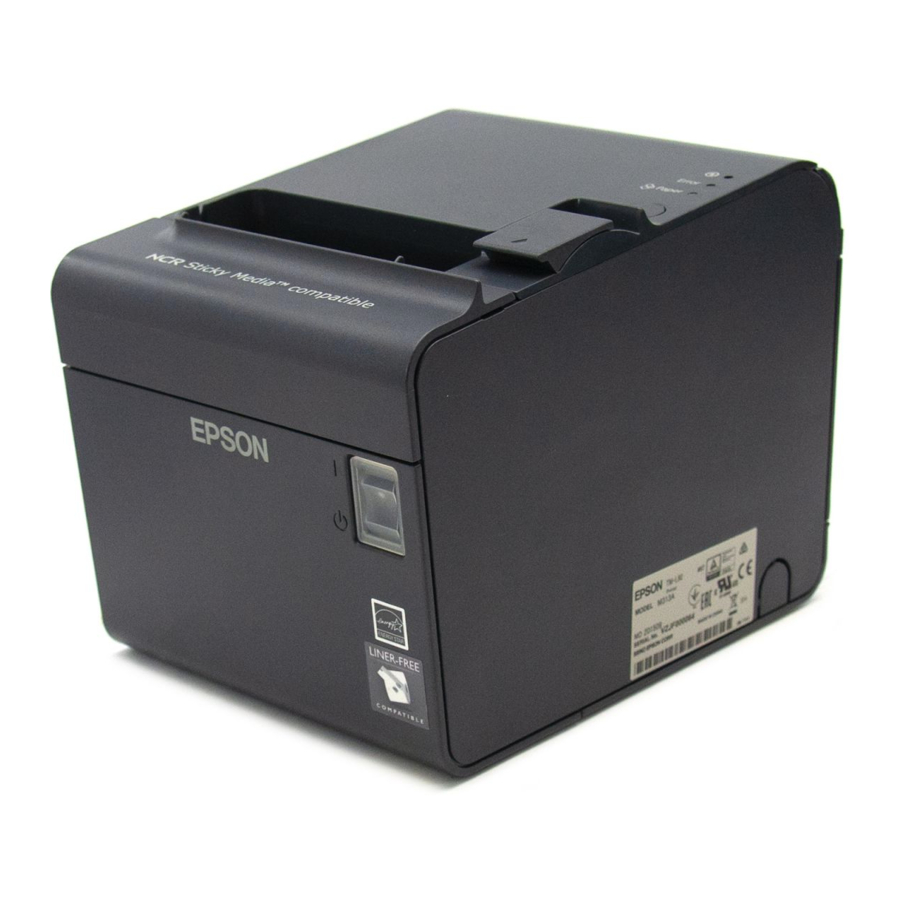
Page 17: Name And Description Of Each Part
* Refer to page 2-19 for the location of the DIP switches. * Another FEED button is located under the roll paper cover. Refer to page 2-23 for the location. Rev. B TM-L90/TM-L90 with Peeler Technical Reference Guide Printer Part Names cutter cover manual cutter roll paper cover... -
Page 18: Part Names (Tm-L90 Peeler Specification)
1.2.2 Part names (TM-L90 peeler specification) power switch peeler cover open lever roll paper cover open lever FEED Button control panel * Refer to page 2-19 for the DIP switch positions. * There is also a FEED button under the roll paper cover. Refer to page 2-23 for the position. 1-4 Product Overview Part Names of TM-L90 Peeler Specification cutter cover... -
Page 19: Control Panel
1.2.3 Control Panel FEED button (with TM-L90) Pressing the FEED button feeds the roll paper. The printer paper feed depends on the line feed amount set. However, in the following cases, FEED cannot be used for paper feed. • When the roll paper cover is open •... - Page 20 2. Close the roll paper cover. 3. Press FEED. • If the roll paper is inserted after the roll paper cover is opened and closed, the printer waits for FEED to be pressed, and then the PAPER OUT LED flashes. In this case, press FEED.
-
Page 21: Power Switch
“Starting the Memory Switch Setting mode” on page 2-23 and“Error code” on page F-3 for details.) ❏ Flashes when a self test is in progress or when the printer waits for the macro execution switch to go on. PAPER OUT LED (with the TM-L90 peeler specification) ❏... -
Page 22: Power Switch Cover
TM executes a forced power off. Note: When the DIP switches are set to ON (power switch disabled), use direct control of the printer with ESC/ POS commands. (For details, refer to “TM Printer Operation Performed When Power Supply Switch is Disabled”... - Page 23 TM-L90/TM-L90 with Peeler Technical Reference Guide mode switch To use the peeling issuing mode, move the mode switch to the right. To use the continuous issuing mode, move the mode switch to the left. Rev. B Product Overview 1-9...
-
Page 24: Connectors
1.2.7 Connectors Remove the bottom of the cover as shown in the illustration below. All cables are connected to the connector panel located on the lower rear side of the printer. power Note: The model pictured is a serial interface model. For other information on interfaces and connectors, refer to “Connecting the Cable”... -
Page 25: Chapter 2 Setup
Chapter 2 Setup 2.1 Setup Flow Before using the printer, you need to set various settings to increase the printer's functionality. Configure the printer appropriately depending on the environment. Determine how to install the printer (install it vertically or horizontally) Rev. -
Page 26: Installation Procedures
Avoid resting the printer on the power supply or other cables or other objects. • Consider vibration during paper cutting and drawer usage. Take measures to prevent the printer from moving. • To prevent malfunction of the label peeling sensor, do not locate the printer in direct sunlight. 2-2 Setup Rev. B... -
Page 27: Instructions For Installation
WH-10 for instructions. It is recommended to take some measures so that the printer will be stable when paper is being loaded or a drawer is being used. The DF-10 (velcro fastening) for fixing the printer is provided as an option. - Page 28 WH-10 for instructions. When you use TM-L90 horizontally, peel off the backing sheet of the paper exit guide and attach it as shown below to prevent cut paper from falling inside the printer after paper is cut by the autocutter.
- Page 29 TM-L90/TM-L90 with Peeler Technical Reference Guide CAUTION: When using the paper exit guide, do not use roll paper with a core that is smaller than the specification (inside diameter: 25.4 mm, outside diameter: 31.4 mm). Using a smaller one may cause a paper jam at the attached paper exit guide. paper exit guide Rev.
-
Page 30: Adjusting Roll Paper Near-End Detection Position
2.3 Adjusting Roll Paper Near-End Detection Position 2.3.1 With TM-L90 Below are three situations when roll paper N.E. detector adjustment is required. ❏ When changing the way of installation. (Vertically ❏ To adjust the location of detection to suit the diameter of the roll paper core used. ❏... - Page 31 In either case (vertical or horizontal), adjust the detector so that its tab comes out from the hole near the bottom of the printer. (Refer to “Adjusting Roll Paper Near-End Detection Position” on page 2-6, “Adjustment Positions of N.E. Detector” on page 2-8 Note: When changing the position of the N.E.
- Page 32 N.E. detector holder shown in the illustration “N.E. Detector Holder” on page 2-8 and adjust the position. Note: Note that the direction to move the roll paper N.E. detector varies depending on the method of printer installation (vertical/horizontal). Adjustment Position Number Specified Thermal Paper Dimension...
- Page 33 6. Tighten the detector adjustment screw using a coin or similar tool. 7. Move the N.E. detect lever by hand (finger) to confirm that it moves freely. Check that the N.E. detect lever is operating properly. 8. Load the roll paper. 9.
-
Page 34: With The Tm-L90 Peeler Specification
2.3.2 With the TM-L90 peeler specification In the following 2 cases, it is necessary to adjust the position of the roll paper near end sensor. ❏ When adjusting the detection position according to the thickness of the roll paper core ❏... - Page 35 4. Using a coin or similar object, loosen the sensor adjustment screw. sensor adjustment screw 5. Adjust the roll paper near end sensor so that the claw of the roll paper near end sensor projects from the hole near the bottom of the device. (Refer to “Part names and the locations of N.E.
- Page 36 Note: Move the N.E. detector in the direction shown by arrow. Adjustment scale Note: Adjust the sensor while checking the position of the parts circled in the following figure. when the sensor holder position is #1 2-12 Setup Near end sensor holder Outside diameter of specified thermal paper Approximately 36 mm {1.42"} Approximately 41 mm {1.61"}...
- Page 37 7. Using a coin or similar object, tighten the sensor adjustment screw. 8. Push the near end sensor with your finger and check that it moves smoothly. push the near end sensor with your finger and check that it moves smoothly 9.
-
Page 38: Connecting Power Supply Unit (Ps-180)
2.4 Connecting Power Supply Unit (PS-180) Be sure to use the EPSON PS-180 or the equivalent product as the power supply unit. WARNING: Always use the EPSON PS-180 or equivalent product as the power supply unit. Using a nonstandard power supply can result in shocks and even fire. -
Page 39: Caution About Power Supply Unit And Supply Voltage
DC24V). Note: When removing the DC cable connector from the EPSON PS-180, first confirm that the power supply cable has been disconnected from the power supply unit; then grasp the arrow marked section of the connector and pull straight out. -
Page 40: Autocutter Settings (Tm-L90 Only)
You can't configure the autocutter setting (Partial cut/Full cut) through a software command. You can't change from partial cut setting to full cut setting after using the printer with partial cut setting. Since the partial cut doesn't use the tip of the blade, it might have deteriorated. Contact the nearest EPSON service center if you'd like to do the above change. - Page 41 4. Remove the single screw retaining the cutter unit and loosen the screw indicated by the circle in the illustration below. Remove this screw 5. Lift the top of the cutter unit upward and remove it. Rev. B TM-L90/TM-L90 with Peeler Technical Reference Guide Lift upwards Loosen this screw Cutter unit...
- Page 42 6. Moving the cutter unit in a lateral direction, shift to the dowel position of the desired cut method. dowels Partial cut 7. Secure the cutter unit again using the removed screw and the loosened screw. 8. Install the cutter cover. 9.
-
Page 43: Setting Roll Paper Width
Note: If a printer has already been used, the paper width cannot be changed from narrow to wide. This is because the part of the head that made direct contact with the platen may have been damaged when narrow roll paper was used. - Page 44 3. As shown below, insert the roll paper spacer so that the front edge goes through the notch in the printer, and fit the protrusion of the roll paper spacer on the shaft. front edge shaft 4. Push the roll paper spacer until it clicks.
-
Page 45: Dip Switch Settings
The DIP switches are inside the roll paper cover. Before setting DIP switches, remove the DIP switch cover. Note: Set the DIP switches after turning off the printer. The settings will not be enabled if they are set with the power on. Rev. B... - Page 46 DIP switches 2 to 8 are for serial communication. Not used in parallel communication. Note: When using an OPOS or Advanced Printer Driver, do not change the DIP switch 1-1 from the OFF position (power supply switch enabled). The printer may not operate normally if the DIP switches are set to ON.
-
Page 47: Setting Memory Switches
DIP switches 2 to 8 are for serial communication. Not used in parallel communication. Note: When using an OPOS or Advanced Printer Driver, do not change DIP switch 1-1 from the OFF position (power supply switch enabled). The printer may not operate normally if the DIP switches are set to ON. -
Page 48: Items That Can Be Set In The Memory Switch Setting Mode
2.8.1 Items that can be set in the memory switch setting mode The items that can be set in the memory switch setting mode are as follows. ❏ Autocutter settings (TM-L90 only) ❏ Paper selection / print density ❏ Serial communication conditions •... -
Page 49: Starting The Memory Switch Setting Mode
4. While the POWER, ERROR, and PAPER OUT LEDs are on, press FEED inside the printer twice. 5. Close the cover. The printer will print out a guidance for the memory switch setting mode and then enter the memory switch setting mode.With the peeling issuing mode, after closing the roll paper cover, the PAPER OUT LED flashes. -
Page 50: Ending Memory Switch Setting Mode
2.8.3 Ending Memory Switch Setting mode Once the setting is completed, the contents of the setting are stored; then the printer executes the initialization. When initialization is finished, the printer returns to normal operating mode. Note: We recommend that you to perform the memory switch setting after finishing the paper layout setting since the roll paper cover needs to be opened and closed for the memory switch setting. -
Page 51: Operating Procedure Of Memory Switch Settings
The procedures used for this process are described below. Entering Memory Switch Settings Mode 1.Open the roll paper cover, and turn on the power while pressing FEED inside the printer. You need to keep pressing the FEED button until the POWER, ERROR, and PAPER OUT LED come on. - Page 52 Selecting individual settings ❏ Setting autocutter (TM-L90 only) First, select the setting for the paper to use by the number of times FEED is pressed. Press the FEED button the number of times required to select the desired autocutter setting. Press FEED button 0 times: 1 time:...
- Page 53 ❏ Communication Condition To select Transmission Conditions, first choose "Serial Interface Settings", then select "Data Length, Handshake, or Parity." Note: The serial communication conditions in the memory switch setting mode take effect only when selecting "Set using memory switches" for the DIP switch 2. •...
- Page 54 • Data Length, Handshake or Parity Press the FEED button the number of times required to select the desired "Data length, Handshake or Parity" as the communication conditions. Press FEED button 0 times: 1 time: 2 times: 3 times: 4 times: 5 times: 6 times: 7 times:...
- Page 55 When using label roll paper that can't be selected in the memory switch setting mode within the range from 38 mm to 80 mm, configure the paper width using any one of 3 control systems: OPOS, Advanced Printer Driver, or ESC/POS. The brief introduction of the control systems is in “Introduction of Control Methods” on page 4-1.
-
Page 56: Other Settings
Send the error recovery command. (Since the printer paper layout is not changed, a paper layout error recurs unless correct paper is loaded.) No change... - Page 57 3 times: 4 times: 5 or more times: Note: A paper layout error occurs when the paper layout set to the printer differs from that of the loaded paper. ❏ FEED button operational settings (TM-L90 peeler specification continuous issuing mode only) With the TM-L90 peeler specification, this sets the operation when FEED is pressed.
- Page 58 Besides the items that can be set in the memory switch setting mode, you can set a variety of items using the utility software for TM series printers provided by Epson. The utilities are explained in “Various Utilities” on page 4-7. For details, refer to the relevant materials.
-
Page 59: Memory Switch Functions
2.9 Memory Switch Functions This printer has the following software switches, called memory switches, in the non-volatile memory. • Msw 1, Msw 2, Msw 8 • Customized values • Serial communication conditions These settings can be made by the memory switch setup utility (see page 4-7) or ESC/POS commands. - Page 60 When [Msw 8-2] is OFF, the paper layout is automatically measured and saved into the non-volatile memory of the printer after recovery from the error. If [Msw8-2] is ON, the printer paper layout is not changed after error recovery. If the correct paper is not inserted, the paper layout error will occur again.
- Page 61 The maximum print speed is available for only the one-part energizing mode. However, if the print duty is too high in the one-part energizing mode, the printer will automatically reduce the printing speed. The four-part energizing mode reduces power consumption.
-
Page 62: Tm-L90 Peeler Specification Memory Switch Settings
2.9.2 TM-L90 peeler specification memory switch settings Among the settings shown below, some can be set with the memory switch setting mode. Refer to page 2-27. MSW1 Function Send power on notification Select receive buffer capacity Conditions for Busy status Data processing when reception error occurs Automatic line feed Reserved... - Page 63 Refer to “Setting Paper Layout” on page 2-45 for the paper layout. When [Msw 8-6] is set to "Feeding paper to the print starting position at power on is disabled", the printer does not execute the operation of feeding paper to the print starting position at power on (the printer executes the operation when its cover is opened and closed).
- Page 64 The maximum print speed is available for only the one-part energizing mode. However, if the print duty is too high in the one-part energizing mode, the printer will automatically reduce the printing speed. The four-part energizing mode reduces power consumption.
-
Page 65: Paper Loading Method
Do not touch the manual cutter with your hands when installing or replacing roll paper. Touching the manual cutter may result in injury. For the TM-L90, when the printer is placed horizontally, the raised roll paper cover may close suddenly depending on the inclining angle of the printer. Take care not to get your finger caught in it. -
Page 66: With The Tm-L90 Peeler Specification
3. If there is a roll paper with little paper remaining inside the TM-L90 peeler, take it out. 4. Check that the printer is on. If it is not on, turn it on. 5. Put a new roll paper in the TM-L90 peeler. Make sure that the roll paper is oriented as shown in the following figure. - Page 67 7. As shown in the following figure, pull the end of the paper to the bottom of the square hole above the manual cutter (label peeling sensor), and close the roll paper cover. Note: Matching the leading edge of the roll paper with the printed marks on the printer ensures that the fewest possible labels are ejected automatically. WARNING: Do not close the roll paper cover with your finger still inside the roll paper cover.
- Page 68 2. Press the roll paper cover open lever, and open the roll paper cover. 3. If there is roll paper with little paper remaining inside the printer, take it out. 4. Put new roll paper in the printer as shown in the following figure.
-
Page 69: Setting Paper Layout
(label peeling sensor). Note: Matching the leading edge of the roll paper with the printed marks on the printer ensures that the fewest possible labels are ejected automatically. 7. Pressing down the end of the paper, close the roll paper cover. The printer automatically feeds the paper to the start position. - Page 70 If you use the printer without making a layout setting and a paper out (no paper left) or an error occurs as a result (refer to page F-3), opening and closing the cover automatically sets a new layout. Note: The above automatic layout setting by opening and closing the cover is available with firmware version 1.05 or later.
- Page 71 7. 6.For peeling issuing, set the end of the roll paper in the peeler, and for continuous issuing, set it in the ejection path, and close the roll paper cover. The printer feeds several labels and remembers the label paper size. This completes the task.
- Page 72 5. For peeling issuing, set the end of the roll paper in the peeler, and for continuous issuing, set it in the ejection path, and close the roll paper cover. The printer feeds several labels and remembers the label paper size. This completes the task.
- Page 73 TM-L90/TM-L90 with Peeler Technical Reference Guide Note: L1 and L2 are measured by the printer. See the following sketch for the lengths L1 to L7. Parameters Calculated for Automatic Layout Setting Rev. B Setup 2-49...
-
Page 74: Clearing Paper Layout Setting
This function may be unavailable depending on when you purchased your printer. You cannot use this function if the firmware version of the printer printed in a self test (“Self Test Mode” on page 2-53) is 1.04 or earlier. For more information, please contact your sales representative. -
Page 75: Tm Setup Items (Summary)
7. Close the roll paper cover. The paper information in the NV memory in the printer is cleared, and to indicate that the layout information is cleared, the printer automatically feeds paper. 2.11 TM Setup Items (Summary) Items of TM setup are shown below; refer to the table below for information about setting items and adequate switches. - Page 76 Select receive Select capacity of receive buffer capacity(*) buffer: large or small. Conditions for Select condition for Busy. Busy Status (*) Data processing Select print “?” or ignored. when reception error occurs #6 pin signal Serial interface reset select for reset #25 pin signal Serial interface reset select for reset...
-
Page 77: Operating Mode (Panel Switch Operation)
"If you want to continue SELF-TEST printing, please press FEED button." The printer is now in the self test wait mode. 3. To start a test print, press the FEED button when the printer is in the self test wait mode. 4. Check that the following has been printed. - Page 78 1. With the roll paper cover open, turn on the power while pressing FEED. Keep pressing it until the ERROR LED comes on. The printer status is printed on the paper. 2. When the printer status has finished printing, the following content is printed. Check that the PAPER OUT LED flashes. •...
-
Page 79: Chapter 3 Connecting To The Host Computer And Options
The figure above shows the connector panel for RS-232 interface model printer. The shape of the interface connector varies according to the type of interface used. Be sure to turn off the power supply for both the printer and the host computer unit before connecting the various cables. -
Page 80: Connecting To The Host Computer
3.2 Connecting to the Host Computer 3.2.1 With the RS-232C interface When the TM printer is connected to a host PC with a serial interface, the following connection forms are possible: • Stand alone • Pass-through Connections of available serial cross cables are as follows: The types of cable (Type A or B) varies depending on the combination of the operation method and the handshake for the TM printer. - Page 81 Other DM-D: not available DTR/DSR Pass-through Connections TM printer is connected to DM-D via serial port and DM-D is connected to the host PC via serial port. The following table shows the application control and cable connection types. Rev. B...
- Page 82 The printer comes with hexagon lock bolts with bolt-head threads designed to inch specifications. Users with interface cables that use metric thread screws can replace the inch thread lock bolts with the metric lock bolts that come with the printer using a hexagonal (5 mm) screwdriver. Identified by encircling line mark...
-
Page 83: With The Parallel (Ieee1284) Interface
*1 Only the printer with the USB hub function allows another TM printer to be connected using a USB cable. *2 EPSON does not supply the port driver or similar program necessary to control the USB interface printer with the ESC/POS commands. Control it with the driver (APD, OPOS). - Page 84 100 mA or more consumption current cannot be connected directly to the printer. Note: To use USB model TM printer, you need to install the USB device driver on host computer after connecting TM printer to the host computer. For information on how to obtain the required device drivers and their installation procedures, contact EPSON or your dealer.
-
Page 85: With The Ethernet Interface 'Ieee802.3' (Tm-L90 Only)
3.2.4 With the Ethernet interface 'IEEE802.3' (TM-L90 only) TM printer with the ethernet interface is connected to a network with the ethernet cable via a Hub. <Example>... - Page 86 Never attempt to connect the customer display cable, drawer kick out cable or the standard telephone line cable to the 10 Base-T Ethernet connector. 1. Confirm that the power supplies for both the printer and the host computer have been turned off.
-
Page 87: Connecting To The Drawer
3.3 Connecting to the Drawer CAUTION: Be sure to connect a drawer that meets printer specifications. Connecting a drawer of the wrong specifications may result in damage to both the drawer and the printer. Never connect the telephone line to the drawer kick out connector (labeled "DK"). - Page 88 3-10 Connecting to the Host Computer and Options Rev. B...
-
Page 89: Chapter 4 Application Development Information
TM printer in the Windows standard printer driver operation environment. Note: Status API is the printer control API supplied originally by EPSON. This can be used to get the printer status and send ESC/POS commands. Rev. B... -
Page 90: Epson Advanced Printer Driver Contents
4.1.1.2 EPSON Advanced Printer Driver Contents The installer automatically judges the target PC environment and automatically installs the DLL and software components necessary for operation. You can select the drivers, sample programs, and manuals to be installed. Drivers You can select the driver according to the purpose of use. (Drivers can be installed simultaneously.) -
Page 91: Epson Advanced Printer Driver Support Environment
4.1.1.3 EPSON Advanced Printer Driver Support Environment Supported interfaces • Serial, Parallel, USB, EtherNet Supported OSs (with confirmation of system operation) ❏ WITH TM-L90 • Windows 95 Standard, OSR 2.5 • Windows 98 Second Edition • Windows NT Ver. 4.0 SP5, SP6 •... -
Page 92: Driver Information And Download Destination
OPOS Control proposed by the OLE for Retail POS (hereafter OPOS) Technology Association to supply the OPOS-compliant printer driver (OCX). Use this control method to develop an OPOS-compliant application. EPSON OPOS ADK has the following features. ❏ EPSON OPOS ADK totally supports the development environment required for OPOS... -
Page 93: Epson Opos Adk (Opos Control) Overview
4.1.2.2 EPSON OPOS ADK Contents The installer of EPSON OPOS ADK Ver. 2.10 or later has the silent installation function, which can install the OPOS environment without a user interface, to facilitate installation. With the installer, the following OPOS-compliant OPOS Control for EPSON devices, manuals, various utilities and sample programs can be installed. -
Page 94: Epson Opos Adk Support Environment
(Paper size, single color/two colors selection (two-color printer only), print waiting time setting, etc.) • TM Flash logo utility A bitmap file can be registered to the printer or customer display, for example. • USB device driver Driver necessary to connect the USB interface printer. -
Page 95: Driver Information And Download Destination
ESC/POS commands from an application to the printer. For detailed information on the ESC/ POS commands, please contact EPSON. Note: The printer of Ethernet specifications requires the IP setup utility separately. Please contact EPSON or your dealer to obtain the utility. 4.1.4 Various Utilities We provide the utilities as described below. -
Page 96: Sensors
If the sensor detects the roll paper end, the printer will stop printing even in the process of printing. It is recommended that you mainly use the roll paper near-end sensor and use the roll paper end sensor secondarily. -
Page 97: Offline
Whether the cover is open or not does not affect the status reported by the roll paper end sensor. Note: When OPOS or Advanced Printer Driver is used, do not change the default setting of the memory switch. 4.2.2.2 Offline This printer is not equipped with an online/offline switch. -
Page 98: Receive Buffer
Note: If the printer is used in a location with direct sunlight, even when a label is removed, it may be determined as being present due to misdetection, and the printer continues waiting for label removal status. In this case, press FEED once to return the paper to the next label printing start position. -
Page 99: Setting Of Paper Width
It is recommended to set print density according to paper type for adequate print quality and ensuring reliability. If the set density exceeds what is needed, it may lead to printer head dirt and blank dot printing. Adjust the print density as needed using the memory switch setting mode or memory switch setting utility. -
Page 100: Barcode Printing
CODABAR (NW-7) CODE 93 CODE 128 Refer to each document of OPOS, Printer Driver or ESC/POS commands for the setting/ printing procedures of each barcode. 4.7 CODE 128 Barcode The CODE 128 barcode allows a single barcode character to represent one character of a full- ASCII 128-character set or two-digit number from among the combinations of 103 different bar code characters and three different code sets. -
Page 101: Application Development Information
Printable characters for code set A Transmission data Hexadecimal Decimal characters code code " & Rev. B TM-L90/TM-L90 with Peeler Technical Reference Guide Transmission data Hexadecimal Decimal characters code code < > Application Development Information 4-13 Transmission data Hexadecimal Decimal characters code code... - Page 102 Printable characters for code set B Transmission data Hexadecimal Decimal characters code code " & < > 4-14 Application Development Information Transmission data Hexadecimal Decimal characters code code Transmission data Hexadecimal Decimal characters code code 7B,7B 123,123 — FNC1 7B,31 123,49 FNC2 7B,32...
- Page 103 Printable characters for code set C Transmission data Hexadecimal Decimal characters code code Rev. B TM-L90/TM-L90 with Peeler Technical Reference Guide Transmission data Hexadecimal Decimal characters code code Application Development Information 4-15 Transmission data Hexadecimal Decimal characters code code FNC1 7B,31 123,49 CODEA...
-
Page 104: Precautions For Two-Dimensional Code Printing
The reliability of two-color printing differs from that of single-color printing. Refer to “Reliability” on page 6-5 for details. 4.10 NV Memory NV memory is embedded in the printer. Please use NV memory with attention to the following: ❏ The following restrictions apply when performing nonvolatile memory operations (including data store and delete). -
Page 105: Faq List
❏ The printer will sometimes enter the Busy state when data is being written to nonvolatile memory. It is important not to send data from the host computer while the printer is in the Busy state as it will be incapable of processing any received data. - Page 106 Follow the serial communication conditions (page 2-29). There are two ways to set it. Refer to “Items that can be set in the memory switch setting mode” on page 2-24 or “TM Printer Memory Switch Setup Utility” on page 4-7.
- Page 107 “USB full speed mode.” Note: USB2.0 defines three speeds: High speed (480 Mbps), Full speed (12 Mbps) and Low speed (1.5 Mbps). This printer supports only Full speed (12 Mbps) and Low speed (1.5 Mbps).lkLK Rev. B TM-L90/TM-L90 with Peeler Technical Reference Guide ) in Visual Basic.
- Page 108 4-20 Application Development Information Rev. B...
-
Page 109: Chapter 5 Esc/Pos Command-Related Information
POWER LED flashes if a software power off process is executed. * Power off process: The TM printer stores the latest TM printer condition before power down. Refer to the ESC/POS Application Programming Guide for details. -
Page 110: When The Power Supply Switch Is Enabled
5.1.2.2 When the Power Supply Switch is Disabled When the power off command is sent from the application, the POWER LED of the TM printer flashes, and the printer waits for the system power to be turned off. (“Error (ERROR) LED” on page F-2.) -
Page 111: Customizing Printer
❏ The printer will sometimes enter the Busy state when data is being written to nonvolatile memory. It is important not to send data from the host computer while the printer is in the Busy state as it will be incapable of processing any received data. -
Page 112: Printer Status
Use the following procedure to output a hexadecimal dump. 1. With the roll paper cover open, press and hold down the FEED button to turn on the printer. 2. Close the roll paper cover. -
Page 113: Chapter 6 Product Specifications
Chapter 6 Product Specifications 6.1 Product Specifications 6.1.1 TM-L90 Thermal line, 8 dots/mm × 8 dots/mm (203 dpi × 203 dpi) Print method Print width 80 mm (factory setting) or 38 to 70 mm can be set using a roll paper spacer Cutting method Separated-blade scissor Cut type... - Page 114 Note: Install the paper exit guide packed in the box with the printer when the autocutter is used with a full cut, positioning the printer horizontally. If the printer is installed horizontally without the paper exit guide and the autocutter full cut is used, a cut sheet may drop in the paper path and it may cause a double-cut, paper jam, or autocutter error.
-
Page 115: Tm-L90 Peeler Specification
6.1.2 TM-L90 peeler specification Thermal line, 8 dots/mm × 8 dots/mm (203 dpi × 203 dpi) Print method Print width 80 mm (factory setting) or 38 to 70 mm can be set using a roll paper spacer Manual cutter With continuous issuing, it is possible to cut the paper by hand specification 100 µm or less Possible thickness... -
Page 116: Print Specifications
Print Speed Carriage return width Note: The print speed listed above is the value when the printer prints with the default print density level at 24 ° V and 25 C. The print speed may be changed automatically with the condition of the supply voltage or the head temperature. -
Page 117: Reliability
70 km {43.5 miles} of running length.) 10,000,000 lines printed (3.75 mm {0.15"} for one line) (The value above is calculated based on the printer using 15-line feeding and 10-line printing repeatedly with a 145 µm paper thickness. - Page 118 Vibration resistance Impact resistance Acoustic noise (operating) The values in the above table are based on use of EPSON specified paper. 6-6 Product Specifications When packed: Frequency: 5 to 55 Hz Acceleration: Approximately 19.6 m/s Sweep: 10 minutes (half cycle)
-
Page 119: Tm-L90 Peeler Specification
Acoustic noise (operating) The values in the above table are based on use of EPSON specified paper. Depending on the paper, paper dust and adhesive may stick to the platen, head, and peeler unit. Rev. B TM-L90/TM-L90 with Peeler Technical Reference Guide Issues 1,000,000 labels (With feed direction label length of 25.4 {1 inch} to 63.5 mm {2.5... -
Page 120: Character Specifications
6.4 Character Specifications Character Specifications Item Character type Alphanumeric International Extended graphics JIS (JISX0208-1990) Special font Character configuration Character dimensions Character Configurations and Dimensions ✕ Font A 12 ✕ Font B 10 ✕ Font C 8 ✕ Kanji 24 ✕ Kanji 20 ✕... -
Page 121: Paper Feed Specifications
Font C Bit image ❏ When the printer is placed in the wait state for data from the host during printing, it temporarily stops printing and paper feed. When data is entered and printing restarts, paper feed may be disturbed between 1 to 3 dot lines at a print start. This especially affects the printing of a bit image. -
Page 122: Printing Area
6.7 Printing Area 6.7.1 Thermal Paper Note: The printable area may be out of alignment by 2 mm {0.08"} maximum (left or right), due to the paper position or tolerance of parts. Therefore, the print area must be set in the range of more than 2 mm from the edges of the paper. -
Page 123: Label
6.7.2 Label Allow 2.8 mm or more from the left and right edges, and 1.5 mm or more from the top and bottom edges for the printable area. 2.8 or more Note: If the margins are not set, the printing may be off the label due to paper misalignment or the part tolerance. -
Page 124: Printing Position In Relation To Cutter Position (Tm-L90)
6.8 Printing Position in Relation to Cutter Position (TM-L90) The TM-L90 printing position and cutter positions are shown in the following figure. Manual-cutter position Auto-cutter blade position Center of the print dotline Printing Position in Relation to Cutter Position Note: The values in the figure are central values. -
Page 125: Printing Position, Peeling Position, Manual Cutter Position (Tm-L90 Peeler Specification)
6.9 Printing Position, Peeling Position, Manual Cutter Position (TM-L90 Peeler Specification) The TM-L90 peeler specification printing position, peeling position and manual cutter positions are shown in the following figure. peeling label sensor Printing Position in Relation to Cutter Position Note: The values in the figure above are design center values, and since the paper may be warped or irregular, allow a sufficient margin when setting the cutting position of the manual cutter. -
Page 126: Overview Of External Dimensions
6.10 Overview of External Dimensions ❏ Height: 203 mm ❏ Width: 140 mm ❏ Depth: 148 mm ❏ Weight: Approximately 1.9 kg (without roll paper) External view (TM-L90) 6-14 Product Specifications External Appearance (TM-L90) [Units: mm] Rev. B... - Page 127 External view (TM-L90 Peeler Specification) [Units: mm] External Appearance (TM-L90 Peeler Specification) Note: As the printer is partly made of coated steel-faced plate, the edges of it may rust. However, it doesn't affect performance of the printer. Rev. B Product Specifications 6-15...
-
Page 128: Operating Specifications
6.10.1 Operating specifications Item Temperature When printing During storage Humidity When printing During storage 6-16 Product Specifications Specifications 5 to 45 °C {41 to 113 °F} -10 to 50 °C {14 to 122 °F} (except for paper) 10 to 90% RH 10 to 90% RH (except for paper) Rev. -
Page 129: Appendix A Interface And Connectors
Select one of the following using DIP switch 6 or the memory switches (switch operation/command (operation). ❏Even ❏Odd 1 or more bits However, the stop bit of the transfer data from the printer is fixed at 1 bit. Dsub-25pin (female) connector Interface And Connectors A-1... -
Page 130: Functions Of Each Connector Pin
SPACE indicates that the printer is ready to receive data. The signal is always SPACE except in the following cases: • During the period from when the power is turned on to when the printer is ready to receive data. -
Page 131: Xon/Xoff
When the printer goes from online to offline mode and the receive buffer is full, XOFF is not transferred. When memory switch Msw 1-3 is off, XON is not transferred as long as the printer is offline even if a receive buffer full state has been cleared. -
Page 132: Ieee1284 Parallel Interface
* n before the signal name indicates active LOW. ❏ Reverse Mode The status data transmission from the printer to the host proceeds in the Nibble or Byte mode. This mode allows data transmission from the asynchronous printer under the control of the host. -
Page 133: Interface Signals
A.2.2 Interface Signals Connector Pin Assignment Source Host Host/Ptr Host/Ptr Host/Ptr Host/Ptr Host/Ptr Host/Ptr Host/Ptr Host/Ptr Printer Printer Printer Printer Host Printer Host Printer Printer Printer Host *NC : None Connect ND : Not Defined Rev. B TM-L90/TM-L90 with Peeler Technical Reference Guide... - Page 134 Note: A signal name prefixed by "n" indicates an "L" active signal. Bidirectional communications cannot take place unless all signal names for both sides correspond to each other. Connect all signal lines using twisted pair cables. Connect the return side to the signal ground level. Make sure that the signals satisfy electrical characteristics.
-
Page 135: Appendix B Consumable Specifications
For information on TM-L90 paper, see below. For information on TM-L90 peeler specification paper, refer to "TM-L90 with Peeler Roll Paper" on page B-13 B.1 TM-L90 Roll Paper This printer can use receipt roll paper and label roll paper with the following roll paper specifications: Paper type... -
Page 136: Specified Receipt Roll Paper
B.1.1.1 Specified Receipt Roll Paper Epson provides the following: Roll paper Printing type no. method NTP080-80 Thermal NTP060-80 Thermal NTP080-ATG Thermal NTP080-RB Thermal (two-color) Note: The TM-L90 can use thermal roll paper with width of 38 ~ 70 mm or roll paper with width of 80 mm. -
Page 137: Print Density Adjustment
B.1.1.3 Print Density Adjustment For best print quality and reliability, select the proper print density for the paper type used as described in the table below. If printing is performed with a density that exceeds the density described in the table below, the reliability ("TM-L90" on page 6-5) is not guaranteed. Print density can be set with a software command. -
Page 138: In Case That Paper Other Than The Specified Original Paper Is Used
B.1.1.5 In case that paper other than the specified original paper is used If the paper other than the specified original paper is used, confirm whether the paper meets the requirements for the thickness, the peeling strength, and the transparency rates. B.1.1.6 Requirements for Black Mark Position for Receipt Paper When manufacturing receipt paper with black marks, be sure to make paper that meets the following requirements. -
Page 139: Die-Cut Label Roll Paper
B.1.2 Die-Cut Label Roll Paper B.1.2.1 Die-Cut Label Paper Die-cut label paper is shown below. Example of transparency label roll paper B.1.2.2 Specified Die-Cut Label Roll Paper Specifications Epson provides the following: Roll paper Printing type no. method NTL080-901 Thermal... -
Page 140: Specified Original Paper
Note: The TM-L90 can use thermal roll paper with width of 38 ~ 70 mm or roll paper with width of 80 mm. For two-color thermal roll paper, "Notes on Two-Color Paper Handling" on page B-23. If solid printing or outline character printing on a label is executed, the print quality may be decreased. B.1.2.3 Specified Original Paper Use the following original paper types for die-cut label roll paper: The type number with (*) indicates that it is used for specified die-cut label roll paper. -
Page 141: In Case That Paper Other Than The Specified Original Paper Is Used
Requirements for the thickness of the die-cut label paper, peeling strength against backing paper, and the adhesive agent that can be used with the printer are shown in the figure below: Die-Cut Label Paper Thickness, Peeling Strength, and Adhesive Agent Peeling strength of the label against backing paper, measured by FINAT FTM-1 (Europe), ASTM D3330/D3330M-02 (U.S.A.). -
Page 142: Requirements For Die-Cut Label Size
B.1.2.8 Requirements for Die-Cut Label Size When manufacturing die-cut label paper, be sure that the paper meets the following requirements. Note: ❏ Be sure to set the cutting position (L4) between labels. ❏ Be sure that the distance from the cutting position to the print starting position (=L3-L4) is 3.6 mm {0.14"} or more. -
Page 143: Requirements For Transparency Rate Of Die-Cut Label Paper
B.1.2.9 Requirements for Transparency Rate of Die-Cut Label Paper If transparency (without black marks) label is used, use a label that meets the following requirements so that the printer can recognize the label position: Note: ❏ Transparency rates are measured by the Macbeth TD-904 (with a filter for infrared) photometer. The... -
Page 144: Requirements For Black Mark Position Ii
B.1.2.12 Requirements for Black Mark Position II The black mark positions on the paper to be manufactured must meet the requirements in the figure below (the reflective rate is measured using the back of the paper, the non-printing side): ❏ Black mark length in vertical: 4 ~ 7.5 mm {0.157~ 0.295"} ❏... -
Page 145: Continuous Label Roll Paper
Compared with die-cut label, it is economic because of no die-cut cut-off edges. Note: Cut-off edges make it easier to remove a label from backing paper. B.1.3.2 Specified Continuous Label Roll Paper Epson provides the following: Roll paper Printing type no. -
Page 146: Print Density Adjustment
B.1.3.3 Print Density Adjustment For best print quality and reliability, select the proper print density for the paper type used as described in the table below. If printing is performed with a density that exceeds the density described in the table below, the reliability ("TM-L90" on page 6-5) is not guaranteed. Print density can be set with a software command. -
Page 147: Tm-L90 With Peeler Roll Paper
B.2 TM-L90 with Peeler Roll Paper This printer can use receipt roll paper and label roll paper with the following roll paper specifications: Paper type Form Paper width Take-up roll paper width Roll paper spool diameter (inside) Roll direction Roll end position Outside diameter (*) Using roll paper with an inside diameter of 25.4 mm {1"} or less may decrease the detection accuracy of the roll... -
Page 148: Print Density Adjustment
❏ Two-color thermal roll paper type no.: (*) PD750R (paper thickness: 75 µm) Note: If specified original roll paper is not used, the thermal head may be damaged due to friction depending on paper. B.2.1.2 Print Density Adjustment For best print quality and reliability, select the proper print density for the paper type used as described in the table below. -
Page 149: Requirements For Black Mark Position For Receipt Paper
B.2.1.4 Requirements for Black Mark Position for Receipt Paper When manufacturing receipt paper with black marks, be sure to make paper that meets the following requirements. The reflecting rates of black mark portions (1) and non black mark portions (2) must meet the combinations shown in the table below: ❏... -
Page 150: Die-Cut Label Roll Paper
B.2.2 Die-Cut Label Roll Paper B.2.2.1 Die-Cut Label Paper Die-cut label paper is shown below. Example of transparency label roll paper Note: The TM-L90 can use thermal roll paper with width of 38 ~ 70 mm or roll paper with width of 80 mm. For two-color thermal roll paper, "Notes on Two-Color Paper Handling"... -
Page 151: Print Density Adjustment
Requirements for the thickness of the die-cut label paper, peeling strength against backing paper, and the adhesive agent that can be used with the printer are shown in the figure below: Die-Cut Label Paper Thickness, Peeling Strength, and Adhesive Agent Peeling strength of the label against backing paper, measured by FINAT FTM-1 (Europe), ASTM D3330/D3330M-02 (U.S.A.). -
Page 152: Requirements For Die-Cut Label Size
B.2.2.7 Requirements for Die-Cut Label Size When manufacturing die-cut label paper (with or without black marks), be sure that the paper meets the following requirements. Note: ❏ Be sure to set the cutting position (L4) between labels. ❏ Be sure that the distance from the cutting position to the print starting position (=L3-L4) is 3.6 mm {0.14"} or more. -
Page 153: Requirements For Transparency Rate Of Die-Cut Label Paper
B.2.2.8 Requirements for Transparency Rate of Die-Cut Label Paper If transparency (without black marks) label is used, use a label that meets the following requirements so that the printer can recognize the label position: Note: ❏ Transparency rates are measured by the Macbeth TD-904 (with a filter for infrared) photometer. The... -
Page 154: Requirements For Black Mark Position I
B.2.2.10 Requirements for Black Mark Position I The black mark positions on the paper to be manufactured must meet the requirements in the figure below. The reflective rates of the black mark portions 1 and label portions 2 must meet the combinations shown in the table below (the reflective rate is measured using the back of the paper, the non-printing side): Reflecting rate for black mark portion 1... -
Page 155: Requirements For Black Mark Position Ii
B.2.2.11 Requirements for Black Mark Position II The black mark positions on the paper to be manufactured must meet the requirements in the figure below (the reflective rate is measured using the back of the paper, the non-printing side): ❏ Black mark length in vertical: 4 ~ 7.5 mm {0.157~ 0.295"} ❏... -
Page 156: Notes On Paper Handling
❏ Extended exposure to direct light (as with placement of the printer near windows) may cause discoloration or faded printing. ❏ When the printer is not used for one week or more, it is recommended not to leave the thermal paper between the platen and the print head. -
Page 157: Notes On Two-Color Paper Handling
B.3.3 Notes on Two-Color Paper Handling ❏ Two-color printing can be performed by selecting two-color paper with the memory switch (customized value) and using two-color paper as the print paper. ❏ In two-color printing, the hue might not be clear, depending on printing patterns. ❏... - Page 158 Rev. B B-24 Consumable Specifications...
-
Page 159: Appendix C Character Code Table
TM-L90/TM-L90 with Peeler Technical Reference Guide Appendix C Character Code Table C.1 Page 0 (PC437 : USA, Standard Europe) (International character set : when America is selected) Rev. B Character Code Table C-1... -
Page 160: Katakana
C.2 Page 1 (Katakana) Rev. B C-2 Character Code Table... -
Page 161: Pc850: Multilingual
TM-L90/TM-L90 with Peeler Technical Reference Guide C.3 Page 2 (PC850: Multilingual) Rev. B Character Code Table C-3... -
Page 162: Pc860: Portuguese
C.4 Page 3 (PC860: Portuguese) Rev. B C-4 Character Code Table... -
Page 163: Pc863: Canadian-French
TM-L90/TM-L90 with Peeler Technical Reference Guide C.5 Page 4 (PC863: Canadian-French) Rev. B Character Code Table C-5... -
Page 164: Pc865: Nordic
C.6 Page 5 (PC865: Nordic) Rev. B C-6 Character Code Table... -
Page 165: Wpc1252
TM-L90/TM-L90 with Peeler Technical Reference Guide C.7 Page 16 (WPC1252) Rev. B Character Code Table C-7... -
Page 166: Pc866: Cyrillic #2
C.8 Page 17 (PC866: Cyrillic #2) Rev. B C-8 Character Code Table... -
Page 167: Pc852: Latin2
TM-L90/TM-L90 with Peeler Technical Reference Guide C.9 Page 18 (PC852: Latin2) Rev. B Character Code Table C-9... -
Page 168: Pc858: Euro
C.10 Page 19 (PC858: Euro) Rev. B C-10 Character Code Table... -
Page 169: Blank Page
TM-L90/TM-L90 with Peeler Technical Reference Guide C.11 Page 255 (Blank page) UD:undefined Rev. B Character Code Table C-11... -
Page 170: International Character Set
C.12 International Character Set Country America France Germany Denmark I Sweden Italy Spain I Japan Norway Denmark II Spain II Latin America Korea C-12 Character Code Table Rev. B... -
Page 171: D.1 Ps-180
Appendix D Option Specifications This appendix describes the optional power supply (PS-180). D.1 PS-180 D.1.1 Electrical Characteristics ❏ Input conditions Input voltage (rating): Frequency (rating): Power consumption (rating): AC switch ❏ Output conditions Output voltage (rating): Output current (rating): Output electric power (rating): Output peak current: D.1.2 Case Specifications ❏... -
Page 172: Material
D.1.2.1 Material No specific brominated flame retardants such as PBBE, PBB are used in this product. D.1.3 AC Cable Selection ❏ Select an AC cable that satisfies the following conditions. • Safety Standard product • Plug with P.E terminal ❏ Ground connection: D-2 Option Specifications Ground certainly for safety. -
Page 173: Appendix E Maintenance
If label paper adhesive has stuck to the autocutter, it may dull the cutting edge. In such a case, clean the cutter blade using the following procedure. 1. Turn off the power. 2. Disconnect the printer from the power connector. 3. Open the roll paper cover. Note: If the roll paper cover will not open, take action in accordance with the troubleshooting of the autocutter (page F-8). - Page 174 Adhesive being removed with flat-blade screwdriver WARNING: Do not touch the area beyond the cutter blade edge. To do so may lead to injury to your fingers. Note: Remove the accumulated adhesive behind the edge of the cutter blade. It is not necessary to polish it to a mirror finish.
-
Page 175: Print Head Cleaning
(after printing) before cleaning it. Also, be sure to turn off the printer power before cleaning the print head. Paper dust on the heating elements may lower the print quality. In this case, clean the print head as follows. - Page 176 EPSON recommends cleaning of the thermal head periodically (generally every three months) to maintain receipt print quality. Keep pieces of metal away from contact with the head thermal elements and driver IC as they are extremely susceptible to damage.
-
Page 177: Cleaning The Peeler (Tm-L90 Peeler Specification Only
E.3 Cleaning the peeler (TM-L90 peeler specification only) If label adhesive accumulates on the rollers of the peeler, remove it with the following procedure. 1. Press the peeler cover open lever, and open the peeler cover. 2. Using a waste label or the like, remove the adhesive by dabbing the label on the roller. If it is left as it is, the adhesive may stick to an issued label. - Page 178 Rev. B E-6 Maintenance...
-
Page 179: Appendix F Troubleshooting
Appendix F Troubleshooting F.1 Panel LED and Error Status F.1.1 Power (POWER) LED Power (POWER) LED Item LED color On states Flashing with short intervals *1 Flashing with long intervals *1 *1: Power (POWER) LED flashes according to the following patterns. Execution in Progress End of power-off sequence... -
Page 180: No Roll Paper (Paper Out) Led
When the error status occurs, stop all of the operations (printing, feeding, autocutting, drawer driving, etc.) You may choose to make the printer status BUSY or not depending on the memory switch setting. (Refer to the "Setting Memory Switches" on page 2-23 and "Error code" on page F-3. -
Page 181: Error Code
*2 This is not any failure or abnormal condition; it just indicates an error condition in case the head temperature has become very hot due to the continuous use with heavy printing duty. If an abnormal value is detected because of the circuit, the printer judges it a drive circuit error and it becomes an unrecoverable error. - Page 182 Although normal printer operation is no longer possible when recoverable errors occur, they do not represent printer failure.You can recover from a recoverable error by turning on the power switch or issuing a command from the driver after eliminating the cause.
- Page 183 Programming Guide. ❏ ESC/POS Send the error recover command to the printer For more details, see the ESC/POS Application Programming Guide. Note: Please contact EPSON for the ESC/POS Application Programming Guide. Rev. B TM-L90/TM-L90 with Peeler Technical Reference Guide Troubleshooting F-5...
-
Page 184: Unrecoverable Errors
Unrecoverable errors Normal printer operation is no longer possible when unrecoverable errors occur. The printer may be out of order. Contact the store for repair. ❏ TM-L90 unrecoverable errors Unrecoverable Errors Error name Type of error R/W error in memory... - Page 185 An abnormal operation occurs in UIB. Note: When an unrecoverable error occurs, turn off the power supply immediately. Unplug the power cablefrom the printer body when the power switch is invalid. Rev. B TM-L90/TM-L90 with Peeler Technical Reference Guide Error LED Flash code Approx.320 ms...
-
Page 186: The Autocutter Is Jammed Or The Roll Paper Cover Will Not Open (Tm-L90 Only
Note: There is also a similar slot on the opposite side face. You can easily remove the cutter cover by lifting it while pushing the printer cover out from both sides simultaneously. 3. Remove the cutter cover. 4. Use a ballpoint pen or tweezers to turn the knob in the direction of the arrow indicated until you see the triangle in the window. -
Page 187: When A Paper Jam Occurs (Tm-L90 Peeler Specification
If you make a signal setting different from that of the connected interface while changing the interface reset signal in the memory switch setting mode, the printer may become inoperative (e.g. the FEED switch quits working). - Page 188 Rev. B F-10 Troubleshooting...
-
Page 189: Appendix G Shipping Procedures
Appendix G Shipping Procedures Perform the following measures before shipping the printer. 1. Hold down the POWER switch 3 seconds or more, or turn off the printer from the host computer. 2. Check that the POWER LED is off. 3. Remove the power supply connectors. - Page 190 Rev. B G-2 Shipping Procedures...
- Page 192 EPSON SEIKO EPSON CORPORATION Printed in Japan...
Need help?
Do you have a question about the TM L90 and is the answer not in the manual?
Questions and answers