Epson TM-L90 series Service Manual
Epson tm-l90 series line-thermal printer
Hide thumbs
Also See for TM-L90 series:
- Technical reference manual (212 pages) ,
- Developer's manual (140 pages) ,
- User manual (112 pages)

Related Manuals for Epson TM-L90 series


Summary of Contents for Epson TM-L90 series
-
Page 1: Service Manual
Confidential Service manual TM-L90 series Issued date Issued by English 401392002 Rev.C EPSON... - Page 2 Confidential TM-L90 Service Manual Revision Table Rev. Page Description Rev. A all pages Newly authorized Rev. B viii Add the information of the related documentation Reason for change: The “TM Service & Support Tool“ is release. Add the “power supply unit type in the ”specifications and configurations.
- Page 3 Confidential Rev. Page Description Add the paper types for original and specified paper. Reason for change: To make the explanation easier to understand. 6-10 Add the note about the setting for serial communication conditions. 6-13 Changed the explanation for the ”Capacity of the receive buffer” that is the function for the”memory switch1-2”...
- Page 4 Confidential TM-L90 Service Manual Rev. Page Description Rev. C <Discontinued parts> Sheet, holder guide, (Ref# 176) Sheet, holder guide, C (Ref# 182) Sheet, holder guide, D (Ref# 183 3-26,46,52 The new parts “Spacer Thermal Head“ is added on Thermal Print Head.So the following illustration is changed.
- Page 5 On the earlier of (a) termination of your relationship with Seiko Epson, or (b) Seiko Epson’s request, you must stop using the confidential information. You must then return or destroy the information, as directed by Seiko Epson.
-
Page 6: Table Of Contents
Disassembly and Assembly of the TM-L90 ........ - Page 7 Confidential TM-L90 Service Manual Wall Mounting ................6-2 Setting the Installation Position for the Roll Paper Near-End Detector .
- Page 8 Confidential Autocutter Unit ................B-6 Full cut and partial cut .
-
Page 9: For Safe Repair And Maintenance Work
Confidential TM-L90 Service Manual For Safe Repair and Maintenance Work Key to Symbols The symbols in this manual are identified by their level of importance, as defined below. Read the following carefully before handling the product. WARNING: You must follow warnings carefully to avoid serious bodily injury. -
Page 10: Modular Connector
Confidential CAUTION: When mounting or replacing the paper roll, be careful not to touch the manual cutter, because it is sharp and can injure you. This product contains other metal parts with sharp edges in addition to the cutter. Touching these parts also may cause injury. Parts on the circuit board may become hot during operation. -
Page 11: About This Manual
Confidential TM-L90 Service Manual About this Manual Aim of the Manual This manual was created to provide the information on printer maintenance and repair required by technicians who handle this work. Contents of the Manual The configuration of the manual is as follows. -
Page 12: Related Documentation
Related Documents Name of document Description TM Service & Support Utility User’s This manual is written for the person that repairs or adjusts of the TM-L90. Manual *1) TM-L90 User’s Guide This manual is written for the operator of the TM-L90. -
Page 13: Chapter 1 Product Overview
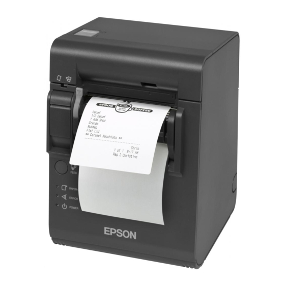
TM-L90 Service Manual Chapter 1 Product Overview The TM-L90 is a line-thermal printer for POS systems that can print on roll paper or a ticket. TM-L90 external view Specifications and Configurations The TM-L90 is configured by combining features from the list below. -
Page 14: Chapter 2 Troubleshooting Guide
Confidential TM-L90 Service Manual Chapter 2 Troubleshooting Guide Preparations for Troubleshooting Before troubleshooting, check and, if necessary, correct the following point. Roll paper cover does not open (cover open lever does not move) 1. Lift up and remove the cutter cover by inserting a flathead screwdriver or similar tool into the cutout in the main case assembly and spreading it in the direction of an arrow. -
Page 15: Before Servicing
Confidential Paper is jammed inside the printer CAUTION: Take care not to let metal objects come into contact with the thermal head. Metal can damage the head. Do not touch the thermal head or radiation plate. Printing can cause them to become very hot. -
Page 16: Symptoms And Solutions
Confidential TM-L90 Service Manual Symptoms and Solutions This explains how to find the source of a problem using the symptom. The numbers in the “Checkpoints” column indicate the order to use to check the problem. If you cannot determine the cause of the problem after checking the first item, proceed to the next number. -
Page 17: How To Use The Self-Test
Confidential How to Use the Self-test There are two types of self-tests. Print tests Print Tests Testing the Thermal Printer Execute this test using the following procedure. Table 2-2 Running the thermal printer print test Step Operation Printer Operation Turn the power supply ON while pressing the The printer will print the status of the printer settings. -
Page 18: Troubleshooting Using The Error Led
Confidential TM-L90 Service Manual Troubleshooting Using the ERROR LED You can learn the cause of a failure by checking the ERROR LED code. The following table shows problems and solutions to repair the printer. Numbers in the "Solutions" column indicate the order to use to check the problem. - Page 19 Confidential Recoverable errors Table 2-4 Recoverable errors Error ERROR LED Blinking Pattern Description Remedy Autocutter error The autocutter does not work Check to see if paper is jammed correctly. around the autocutter. If so that, remove the jammed paper. After then close the roll paper cover, turn it off, and then turn it on again.
- Page 20 Confidential TM-L90 Service Manual Note: When a paper jam is present in the autocutter, turn off the unit and remove the jammed paper. Then turn it on again. Non-recoverable errors CAUTION: When any error shown below occurs, turn off the power as soon as possible.
-
Page 21: Test Points On The Printer Mechanism
Confidential Test Points on the Printer Mechanism Before you replace the main circuit board to see if the printer is repaired, you need to check the printer mechanism. If the motor or the coils are shorted, replacing the main circuit board will not fix the problem. -
Page 22: Chapter 3 Disassembly And Assembly
Confidential TM-L90 Service Manual Chapter 3 Disassembly and Assembly Notes for Assembly and Disassembly Always observe the following precautions when disassembling and assembling the printer. CAUTION: Wear a grounded wrist band when handling the internal circuit boards to prevent damage from static electricity. -
Page 23: How To Read This Chapter
Table 3-1 Structure of this chapter 1st level 2nd level 3rd level Disassembly and Cutter cover assembly of the Connector cover TM-L90 I/F circuit board unit Main assembly case Main circuit board unit Disassembly and Cable wiring assembly of the Roll paper cover unit... -
Page 24: Shortest Route For Disassembly Of Major Parts
Confidential TM-L90 Service Manual Shortest Route for Disassembly of Major Parts The next diagram shows the shortest disassembly route of major parts. Perform disassembly by following this diagram as well as explanations for the target item. For the disassembly procedure of the thermal print head, see page 3-4. -
Page 25: Replacing The Thermal Print Head Assembly
Confidential Replacing the Thermal Print Head Assembly CAUTION: This job may be performed only after turning off the printer and waiting for approximately 10 minutes. The thermal print head assembly may be hot, and otherwise, you might get burned. When performing this job, take anti-static measures, such as wearing a grounded wrist band. - Page 26 Confidential TM-L90 Service Manual 3. Users may choose between partial cut and full cut by adjusting the autocutter unit to the desired position. Check the part shown below to see if the autocutter is set to full cut or partial cut. When you install the autocutter unit, return the unit to the user’s position.
- Page 27 Confidential 5. While holding the two head holder springs so they do not fly out, pull out the spring holder plate. CAUTION: Be sure to hold the two head holder springs while removing spring holder plate. Otherwise, head holder springs may suddenly fly out, creating the danger of eye injury.
- Page 28 Confidential TM-L90 Service Manual Follow the steps below to assemble the parts. 1. Attach the insulating tape on the new thermal print head assembly, as shown below; then lubricate with G-45 along the surfaces on both ends of the head assembly.
- Page 29 Confidential 9. Set the autocutter unit to the user’s position (partial cut or full cut). To select partial cut: adjust the dowel to the position marked P. To select full cut: adjust the dowel to the position marked F. Dowel 10.
-
Page 30: Disassembly And Assembly Of The Tm-L90
Confidential TM-L90 Service Manual Disassembly and Assembly of the TM-L90 First Level Cutter Cover 1. Open the roll paper cover. 2. Remove the cutter cover by spreading area of the main case assembly, as shown below: Roll paper cover Main case assembly Cutter cover Install in the reverse sequence of removal. - Page 31 Confidential Connector Cover With the main assembly upside down, remove the connector cover by pressing its rear section and unhooking the two claws. onnector cover Claw Install in the reverse sequence of removal. 3-10 Disassembly and Assembly Rev.C...
- Page 32 Confidential TM-L90 Service Manual I/F Circuit Board Unit 1. With the main assembly upside down, remove two S6 screws. 2. Remove the I/F circuit board unit. I/F circuit board unit Install in the reverse sequence of removal. Rev.C Disassembly and Assembly 3-11...
- Page 33 Confidential Main Case Assembly 1. With the main assembly upside down, remove two S5 screws and one S3 screw. 2. Remove the main case assembly. Main case assembly CAUTION: When installing the case, do not pinch the lead wire. Doing so may cause failures. Install in the reverse sequence of removal.
- Page 34 Confidential TM-L90 Service Manual Main Circuit Board Unit 1. Remove the cutter lead wire from connector . Then, remove the insulating tape securing the lead wire. When installing, route the cutter lead wire as shown below, and then fix with the insulating tape.
- Page 35 Confidential Main circuit board unit Bottom plate Install in the reverse sequence of removal. 3-14 Disassembly and Assembly Rev.C...
-
Page 36: Disassembly And Assembly Of The Printer Mechanism
Confidential TM-L90 Service Manual Disassembly and Assembly of the Printer Mechanism Note: The term “printer mechanism” is used only for convenience in this document; there are no parts in the actual product that use this name. First Level Cable Wiring 1. - Page 37 Confidential Roll Paper Cover Unit 1. Release the two tabs on the label paper guide from the roll paper cover unit. Tabs Label paper guide 2. Remove the insulating tape that is securing the lead wire of the BM (black mark) paper detector circuit board assembly.
- Page 38 Confidential TM-L90 Service Manual 3. Remove one S1 screw to release the ground wire of the BM paper detector circuit board assembly. Ground wire 4. Disconnect the lead wire of the BM paper detector circuit board assembly from the switch circuit board assembly, and remove the ferrite core.
- Page 39 Confidential 5. Remove the two E-rings (E2). 6. Remove the two cover rotation shafts by pressing them inside. 7. Remove the roll paper cover unit. Then, pull the lead wire of the BM paper detector circuit board assembly out through the clearance in the hinge cover. Cover rotation shafts Hinge cover Roll paper cover unit...
- Page 40 Confidential TM-L90 Service Manual Switch Circuit Board Assembly 1. Remove the cover detector lead wire and the switch circuit board FFC from the switch circuit board assembly. 2. Remove two S2 screws. 3. Remove the switch circuit board assembly by spreading the two hooks of the switch panel holder.
- Page 41 Confidential Sub Circuit Board Assembly 1. Remove two S6 screws. 2. Remove the sub circuit board assembly by pulling it up diagonally and out. Sub circuit board assembly Install in the reverse sequence of removal. 3-20 Disassembly and Assembly Rev.C...
- Page 42 Confidential TM-L90 Service Manual Autocutter Unit 1. Users may choose between partial cut and full cut by adjusting the autocutter unit to the desired position. Check the part shown below to see if the autocutter is set to full cut or partial cut.
- Page 43 Confidential Install with the following steps: 1. Attach the autocutter unit in its installation position. Then, align the two dowels on the frame assembly with the two slits in the autocutter unit. 2. Set the autocutter unit to the user’s position (partial cut or full cut). To select partial cut: adjust the dowel to the position marked P.
- Page 44 Confidential TM-L90 Service Manual Thermal Print Head CAUTION: This job may be performed only after turning off the printer and waiting for approximately 10 minutes. The thermal print head assembly may be hot, and otherwise, you might get burned. When performing this job, take anti-static measures, such as wearing a grounded wrist band.
- Page 45 Confidential 2. Remove the two head holder springs from the spring holder panel by rotating them. 3. Lift up the thermal print head assembly and remove the head FFC from the thermal print head assembly. CAUTION: To prevent static-generated failures, keep the removed thermal print head assembly in an anti-static bag or other suitable container.
- Page 46 Confidential TM-L90 Service Manual Install using the following steps: 1. Attach the insulating tape on the new thermal print head assembly, as shown below; then lubricate with G-45 along the surfaces on both ends of the head assembly. G-45 G-45 Insulating tape 2.
- Page 47 Confidential Hinge Cover 1. Remove two S1 screws and one S2 screw. 2. Remove the hinge cover by spreading the two hooks. 3. Remove the feed sheet from the hinge cover. 4. Remove the DIP switch cover from the hinge cover. Hinge cover Feed sheet...
- Page 48 Confidential TM-L90 Service Manual Label Paper Guide Remove the label paper guide by raising it and pulling it out from the label paper holder groove. Label paper holder Label paper guide Install in the reverse sequence of removal. Rev.C Disassembly and Assembly 3-27...
- Page 49 Confidential Reduction Gears 1. Remove one E-ring (E2). 2. Remove reduction gear C. 3. Remove reduction gear D. Reduction gear D Reduction gear C Install using the following steps: 1. Lubricate the two reduction gear shafts with G-45, in a line-shape. 2.
- Page 50 Confidential TM-L90 Service Manual 5. Lubricate half of reduction gear C with G-45. 6. Lubricate the contact area of frame R and the front frame with G-36. 7. Lubricate the contact area of the frame L assembly and the front frame with G-36.
- Page 51 Confidential Label Paper Holder 1. Remove the lead wire of the LED holder assembly from between the center frame and the front frame. 2. Remove the S1 screw. 3. Pull the label paper holder out straight along the grooves in the frame L assembly and frame R.
- Page 52 Confidential TM-L90 Service Manual Circuit Board Frame 1. Remove four S4 screws. 2. Remove the circuit board frame. Frame L assembly Insulating tape Frame R Circuit board frame Install using the following steps: 1. Affix insulating tape on the right side of the circuit board frame, as shown in the photo above.
- Page 53 Confidential Frame R and Center Frame 1. Remove one S4 screw 2. Remove frame strengthening plate R. 3. Remove one S4 screw 4. Remove frame R. 5. Remove the center frame. 6. Remove one switch screw and remove the cover detector assembly from frame R. Center frame Cover detector assembly Frame L assembly...
- Page 54 Confidential TM-L90 Service Manual Front Frame 1. Remove one S4 screw. 2. Remove frame strengthening plate L. 3. Remove the front frame. Frame strengthening plate L Front frame Install in the reverse sequence of removal. Rev.C Disassembly and Assembly 3-33...
- Page 55 Confidential Paper Feed Motor 1. Remove two W1 washers and one motor ground plate by removing three N1 nuts. 2. Slide out the paper feed motor from the hole in the frame L assembly. 3. Remove the three paper feed motor dampers from the paper feed motor. 4.
-
Page 56: Second Level
Confidential TM-L90 Service Manual Second Level Roll Paper Cover Unit 1. Remove one E2 type E retaining ring, and slide the lever shaft to remove the lever button. Lever shaft Lever button 2. Remove the lead wires of the BM (black mark) paper detector circuit board assembly from the roll paper cover unit. - Page 57 Confidential 3. Remove the three S1 screws and remove the platen holder. CAUTION: When removing the screws near the platen gear, take precautions against touching the gear with the screwdriver. Do not use a screwdriver with a short handle and/or thick shaft, as it can easily touch the gear. Touching the gear may damage it.
- Page 58 Confidential TM-L90 Service Manual 6. Peel off spacer B. Spacer B When assembling, affix the spacer as shown below. Spacer B 7. Peel off the mini-clamp. When assembling, affix it in the direction shown below. Mini-clamp Rev.C Disassembly and Assembly 3-37...
- Page 59 Confidential 8. Remove the two hinge spacers from the roll paper unit. When assembling, make sure you insert the spacers in the direction shown below. Hinge spacer Glossy surface Glossy surface Glossy surface Hinge spacer Install in the reverse sequence of removal. 3-38 Disassembly and Assembly Rev.C...
- Page 60 Confidential TM-L90 Service Manual Autocutter Unit 1. Remove two manual cutter screws 2. Remove the manual cutter. CAUTION: The manual cutter has a sharp blade. Handle it with care. 3. Remove one manual cutter screw 4. Remove the paper cutter cover assembly.
- Page 61 Confidential Install using the following steps: Triangle mark Cutter driving gear Manual cutter Reduction screw Manual cutter A/C gear screws Cutter Manual cutter motor gear Cutter worm Paper cutter cover gear Center of the assembly contact area between the cutter worm gear and the paper cutter cover assembly Long hole in the movable blade...
- Page 62 Confidential TM-L90 Service Manual 11. Adjust the position of the cutter driving gear so that the triangle mark on the cutter driving gear becomes visible through the hole in the paper cutter cover assembly. 12. Install the paper cutter cover assembly onto the cutter frame assembly.
- Page 63 Confidential LED Holder and Cover Plate Spring 1. Pull out the LED holder assembly from the label paper holder while pressing both claws inside. 2. Remove the cover leaf spring. Label paper holder LED holder assembly Lead wire Cover leaf spring Install using the following steps: 1.
- Page 64 Confidential TM-L90 Service Manual NE Detector Assembly 1. Remove the NE detector lead wire from the hook on the label paper holder. 2. Remove one E1 type E retaining ring. 3. Remove the NE detector adjustment screw by rotating it with a coin.
- Page 65 Confidential Install using the following steps: 1. Affix insulating tape on the NE detector lead wire as shown in the photo below. (This process is necessary only if the original NE detector lead wire has insulation tape affixed.) Insulating tape 2.
- Page 66 Confidential TM-L90 Service Manual Auxiliary Holder Plate and Side Plate Guide Shaft 1. Remove one S10 screw. 2. Disengage both projections located in the lower part of the auxiliary holder plate, and pull out the auxiliary holder plate downward, at an angle.
- Page 67 Confidential Install in the reverse sequence of removal. After you have installed the paper holding rollers, lubricate with G-45 at the 16 points shown below. G-45 G-45 G-45 G-45 G-45 G-45 G-45 G-45 G-45 G-45 <Zoom up> 3-46 Disassembly and Assembly Rev.C...
-
Page 68: Third Level
Confidential TM-L90 Service Manual Third Level Platen Holder 1. Remove the fixed blade from the platen holder by raising the blade. When installing the fixed blade, see the drawing below to check the installation direction. CAUTION: The fixed blade is sharp. Handle it with care. - Page 69 Confidential 3. Pull out the lever shaft and remove one E2 type E retaining ring. Lever shaft 4. Remove the cover open lever. Cover open lever 5. Remove the lead wire of the BM (black mark) detection set board from the hooks of the platen holder.
- Page 70 Confidential TM-L90 Service Manual 6. Remove two S1 screws, and remove the BM detector holder. BM detector holder When you assemble the BM detector holder, make sure the shield plate fits into place as shown below. NG (This portion of the shield plate goes up slightly.) 7.
- Page 71 Confidential 8. Remove one S1 screw; then, remove the shield plate. Shield plate 9. Remove one S1 screw, and remove the BM paper detector circuit board assembly. BM paper detector circuit board assembly 3-50 Disassembly and Assembly Rev.C...
- Page 72 Confidential TM-L90 Service Manual 10. Remove the fixed blade holder spring by lifting up the claw. Note: The claw of the fixed blade holder spring is hooked to the platen holder. When removing it, do not pull forcibly, as this may result in deformation. When installing it, make sure the claw has been hooked.
- Page 73 Confidential Important Note About Installing Thermal Print Head Please follow these instructions to install the new thermal print head correctly. Note that the new head has a spacer on it. 1. Cut the plastic sheet with a cutting tool such as a cutter knife. Be sure not to cut the surrounding parts.
-
Page 74: Chapter 4 Adjustment And Settings
Confidential TM-L90 Service Manual Chapter 4 Adjustment and Settings Threshold Value Setting for Detectors Perform this setting when you have replaced any of the following. Items Requiring Setting LED holder assembly BM paper detector circuit board assembly Main circuit board unit Note: If you do not perform this setting or perform it incorrectly, the printer generates the paper layout error. - Page 75 Confidential Note: For details about the settings listed below, see Chapter 6, “Installation.” Setting for the position of the roll paper near-end detector Setting for the roll paper cutting method Roll paper width setting DIP switch settings NV memory settings 4-2 Adjustment and Settings Rev.B...
-
Page 76: Chapter 5 Maintenance, Inspection, Lubrication, And Cleaning
Confidential TM-L90 Service Manual Chapter 5 Maintenance, Inspection, Lubrication, and Cleaning Periodic Maintenance or Inspection There are no parts in this product that require periodic maintenance or inspection. Lubrication There are no parts in this product that require periodic lubrication. -
Page 77: Cleaning The Case
Confidential Cleaning the Case Use a dry cloth or lightly dampened cloth to clean the case. Disconnect the power cord from the wall outlet before doing this. Avoid using alcohol, benzene, thinner, trichloroethylene, or ketone-based substances to remove dirt or foreign matter from the printer, because these substances can affect or damage plastic and rubber parts. -
Page 78: Chapter 6 Installation
Confidential TM-L90 Service Manual Chapter 6 Installation Installation Precautions CAUTION: Do not place the printer in an unstable place (such as on an unsteady base or on a slanted surface). The unit may fall or drop, and may cause injury. -
Page 79: Horizontal Installation
Confidential Horizontal Installation Place the printer with the paper exit facing upward. When you install the printer horizontally, perform the following steps. 1. Attach the switch panel label as shown below. Switch panel labell 2. If the autocutter is set to full cut, attach the paper outlet guide using the paper outlet tape (double-sided tape) as shown below. -
Page 80: Setting The Installation Position For The Roll Paper Near-End Detector
Confidential TM-L90 Service Manual Setting the Installation Position for the Roll Paper Near-End Detector This printer allows you to change the installation position for the roll paper near-end detector using the following procedure. Set the detector based on whether your printer is installed vertically or horizontally. -
Page 81: Adjusting The Detecting Point Of The Roll Paper Near-End Detector
Confidential Adjusting the Detecting Point of the Roll Paper Near-End Detector Below are two reasons for the roll paper to require an NE detector adjustment. To adjust the location of detection for the diameter of the roll paper core. To adjust the amount of remaining paper. 1. -
Page 82: Setting The Paper Roll Cutting Method
Confidential TM-L90 Service Manual Setting the Paper Roll Cutting Method You can choose between partial cut and full cut by adjusting the autocutter unit to the desired position. The steps below show the setting of the cutting method. Note: Once the printer is used, do not change the cutting method from partial cut to full cut, because of the difference in the wear rate on the blades between the areas where the paper passes and the paper does not pass, which can result in a paper-cutting problem. - Page 83 Confidential 4. Adjust the autocutter unit to the desired position. To select partial cut: adjust the dowel to the position marked P. To select full cut: adjust the dowel to the position marked F. Dowel 5. Secure the autocutter unit with the two S4 screws. Make sure the two dowels on the frame assembly engage the two slits in the autocutter unit.
-
Page 84: Setting The Paper Roll Width
TM-L90 Service Manual Setting the Paper Roll Width The TM-L90 accommodates 80 mm {3.15"} wide paper rolls with no adjustments. For rolls from 38 to 70 mm {1.5 to 2.76"} wide, use the label paper spacer included with the printer. -
Page 85: Attaching The Power Switch Cover
Confidential 4. Push the label paper spacer until you feel it click onto the shaft. Check that the label paper spacer slides smoothly to the left and right. 5. Slide the label paper spacer to the appropriate width. You can use the ruler printed inside the printer, aligning the inside edge of the spacer with the desired measurement. -
Page 86: Setting The Dip Switches
Confidential TM-L90 Service Manual For removal, use a sharp-edged object. Power switch cover If you want to turn on or off the power switch with the cover attached insert a sharp edged object into the hole in the power switch cover, and remove portion in the above illustration. -
Page 87: Dip Switch Settings
Confidential DIP switch settings For serial interface models Table 6-2 DIP switch settings for serial interface models Switch number Function Power switch function Disabled Enabled Setting for serial communication To be specified with DIP To be specified with NV conditions switches. - Page 88 Confidential TM-L90 Service Manual Switch number Function Reserved Fixed to off Reserved Fixed to off Reserved Fixed to off Rev.B Installation 6-11...
-
Page 89: Connecting Cables
Confidential Connecting Cables WARNING: Make sure you use the EPSON PS-170 or PS-180 power supply. Using an incorrect power supply may cause fire or electrical shock. CAUTION: When connecting or disconnecting the power supply from the printer, make sure the power supply is not plugged into an electrical outlet. -
Page 90: Setting The Nv Memory
Confidential TM-L90 Service Manual Setting the NV Memory The functions shown below are assigned to the memory system used with this printer. NV memory Customized values Memory switches • Select NV user memory capacity • MSW1 • Select NV graphics memory capacity •... -
Page 91: Paper Layout Automatic Setting Mode
Confidential Follow the steps below to run the Memory Switch Setting Mode. 1. Install a paper roll. 2. With the roll paper cover opened, turn the power on while pressing the FEED button. And You need to hold down the paper FEED button continuously until the ERROR LED lights on;... - Page 92 Confidential TM-L90 Service Manual MSW2 Table 6-7 Memory switch MSW2 Function 0 (off) 1 (on) Reserved Fixed to on Autocutter operation Disabled Enabled Undefined Undefined Undefined Undefined Undefined Undefined MSW8 Table 6-8 Memory switch MSW8 Function 0 (off) 1 (on)
-
Page 93: Customized Values
Confidential Customized Values Table 6-9 Customized values Function Selection Select NV user memory 1KB 64KB 128KB 192KB capacity Select NV bit image None 64KB 128KB 192KB 256KB 320KB 384KB memory capacity Select paper width 38 mm 39 mm • • •... -
Page 94: Chapter 7 Handling
Confidential TM-L90 Service Manual Chapter 7 Handling Safety Precautions WARNING: Shut down your equipment immediately if it produces smoke, a strange odor, or unusual noise. Continued use may lead to fire or electric shock. Immediately unplug the equipment. Only disassemble this product as described in this manual. Do not make modifications to the unit. -
Page 95: Precautions On Handling The Printer
Confidential CAUTION: Do not connect cables other than as described in this manual. Different connections may cause equipment damage and burning. Be sure to set this equipment on a firm, stable, flat surface. Product may break or cause injury if it falls. Do not use in locations subject to high humidity or dust levels. -
Page 96: Precautions On Paper Handling
Confidential TM-L90 Service Manual Precautions on Paper Handling CAUTION: Thermal paper containing Na, K, or CL ions, etc., can adversely affect the heating elements of the thermal head. Be sure to use thermal paper that meets the paper specifications described in Appendix A, “General Specifications.”... -
Page 97: Leds And Button
Confidential LEDs and Button Table 7-2 LEDs and button Name Function POWER LED Lights when the power is on, and is off when the power is off. ERROR LED Off when the printer is online, lights when the printer is offline, and flashes when an error occurs. - Page 98 Confidential TM-L90 Service Manual These methods can be selected by DIP switch 1. Table 7-4 Setting of DIP switch 1 Method DIP switch 1 Power ON/OFF using the power switch Power ON/OFF with the power switch disabled The explanations below show how to power the unit ON or OFF by each method.
-
Page 99: Loading The Paper Roll
Confidential Loading the paper roll CAUTION: The manual cutter blade is sharp. Do not touch it with your hands when mounting or replacing roll paper, because you can be injured. Be aware that the thermal print head and its supporting parts become very hot. Be sure not to touch these parts. -
Page 100: Removing The Roll Paper
Confidential TM-L90 Service Manual 3. Pull out a small amount of roll paper. 4. Then close the paper roll cover. Vertical installation Horizontal installation 5. Tear off the paper as shown. Removing the roll paper Open the roll paper cover, and remove the used paper roll core if there is one. -
Page 101: Appendix A General Specifications
Confidential TM-L90 Service Manual Appendix A General Specifications Printing Specifications Printing method: Thermal line printing 203 dpi × 203 dpi [dpi: dots per 25.4 mm (dots per inch)] Dot density: Paper Specifications Paper type: Specified thermal roll paper The following paper can be used: •... - Page 102 Confidential Paper Specifications Specified roll paper: Roll Width Original 80mm {3.15"} 60 mm {2.36"} 38mm {1.5"} paper Monochrome thermal ENTPD080090 TF60KS-E roll paper Monochrome thermal ENTPE080090 TF11KS-ET roll paper (thickness type) Two-color thermal roll ENTPC080090 PD750R paper Label stock Length Label Width of label 80 mm {3.15"}...
- Page 103 Confidential TM-L90 Service Manual Specified original paper: The following original paper types can be used. Monochrome thermal paper TF60KS-E (Paper thickness 75 µm) (Nippon Paper Industries Co., Ltd.) TF11KS-ET (Paper thickness 145 µm) (Nippon Paper Industries Co., Ltd.) TF50KS-E (Paper thickness 65 µm)(Nippon Paper Industries Co., Ltd.) PD160R (Paper thickness 75 µm) (Oji paper Mfg.
-
Page 104: Autocutter
Confidential Autocutter Either of the following settings can be applied. Table A-1 Autocutter settings Setting Description Partial cut (cutting with one point in left Set by changing the autocutter edge left uncut) unit position. Full cut (completely cut) Note: Once the printer is used, do not change the cutting method from partial cut to full cut, since the wear rate on the blades differs between the areas where the paper passes and where the paper does not, which can result in a paper-cutting problem. -
Page 105: Paper Roll Supply Device
Confidential TM-L90 Service Manual Paper Roll Supply Device Supply method: Drop-in paper roll Near-end detector Detection method: Micro switch Paper roll core Inside: 25.4 mm {1"}, Outside: 31.4 mm {1.24"} diameter: Near-end adjustment: Adjusting screw Fixed position #1 (diameter: approximately 36 mm {1.42"}), #2 (diameter: approximately 41 mm {1.61"}) -
Page 106: Electrical Specifications
Confidential Electrical Specifications Operating voltage: +24 VDC ± 7% (optional power supply: EPSON PS-170 or PS-180) Pin assignments for the power connector: Table A-2 Pin assignment for the power connector Pin # Function +24V N.C. SHELL F.G. Dimensions and Mass Height: Approx. -
Page 107: Environmental Conditions
Confidential TM-L90 Service Manual Environmental Conditions Temperature: Operating: ∼ ° C {23-113 ° F} (See the figure below.) Storage: ∼ ° C {14-122 ° F} (except for paper) Humidity: Operating: ∼ 90% RH (See the figure below.) ∼ Storage: 90% RH (except for paper) [%RH] 34°C, 90%... -
Page 108: Drawer Kick-Out Connector
— +24V is always output through pin 4 during power on. Interfaces Various interface boards (EPSON UB series, except for the UB-P02) can be used. Buttons and Switches Power switch The power switch (non-locking, push switch) on the right part of the front face of the unit turns the printer on or off. -
Page 109: Dip Switches And Nv Memory
Confidential TM-L90 Service Manual DIP Switches and NV Memory For explanations of the DIP switches and the NV memory, see Chapter 6, “Installation.” Indicators Panel LEDs Power (POWER) LED: Green Power is stable. OFF: Power is not stable. Paper roll end (PAPER OUT) LED: Red The paper roll near end or real end is detected. - Page 110 Confidential Appendix A-10 General Specifications Rev.B...
-
Page 111: Appendix B Overview Of The Mechanisms
Confidential TM-L90 Service Manual Appendix B Overview of the Mechanisms This printer consists of the next four units: Cover unit Print/paper feed unit Paper supply unit Autocutter unit The illustration below shows an external view of the printer mechanism: Cover unit... -
Page 112: Cover Unit
Confidential Cover Unit The cover unit is installed onto the paper supply unit by a hinge, and it makes a rotational movement. Attached to the platen holder of the cover unit are the paper feed roller shaft holder, platen, cover open lever, lever shaft, lever button, fixed blade, and reflective photo detector. The reflective photo detector is able to detect the black mark on the non-printing surface of the paper. -
Page 113: Print/Paper Feed Unit
Confidential TM-L90 Service Manual Print/Paper Feed Unit The print/paper feed unit consists of various frames, thermal print head, head holder mechanism, paper feed motor, reduction gear, and cover open detector. Thermal print head Head holder mechanism Platen shaft holder locator... -
Page 114: Thermal Print Head
Confidential Thermal Print Head The thermal print head consists of a head chip that includes the heating element, a driver IC that controls each dot of the heating element, a thermistor that detects the temperature of the thermal print head, radiation plate, and connector. Radiation plate Head chip Driver IC... -
Page 115: Paper Supply Unit
The label guide is attached to the label holder and interlocks with the cover unit. This allows the TM-L90 to receive paper roll in the correct position, whether the unit is installed vertically or horizontally. The guide rollers that receive the paper roll ease the load that occurs during paper feed, improve the paper-feed pitch accuracy, and ease the maximum load applied to the paper feed motor. -
Page 116: Changing The Paper Width
Confidential Changing the paper width The unit can handle paper roll widths of 38 mm to 70 mm {1.5 to 2.76"}, when you install a paper spacer into the label holder. Appearance of paper spacer Paper spacer is attached to the label holder (example) Autocutter Unit The autocutter unit is installed into the print/paper feed unit, and consists of a movable blade,... -
Page 117: Full Cut And Partial Cut
Confidential TM-L90 Service Manual Opening the cover unit separates the two blades. Closing the cover unit while the movable blade is in the standby position makes the fixed blade hit the frame portion of the autocutter unit, and is set to the correct position against the movable blade. -
Page 118: Appendix C Tools
Confidential TM-L90 Service Manual Appendix C Tools Table C-1 Tools Tool Specifications Purpose Source Torque-limiting hexagon box driver Tip size: 5 mm Remove and install the paper Use commercially feed motor available product. The tightening torque for the nut should be between 34.3 to... -
Page 119: Appendix D Parts List
Confidential TM-L90 Service Manual Appendix D Parts List Alphanumeric List Table D-1 Alphanumeric list Name for service manual Name for price list Q’ty Ref.# Note Autocutter unit AUTO CUTTER UNIT Auxiliary holder plate PLATE,HOLDER AUXILIARY BM detector holder HOLDER,BM DETECTOR... - Page 120 Confidential Table D-1 Alphanumeric list Name for service manual Name for price list Q’ty Ref.# Note Frame R FRAME,R Frame strengthening plate L PLATE,FRAME STRENGTHEN,L Frame strengthening plate R PLATE,FRAME STRENGTHEN,R Front frame FRAME,FRONT Handling label LABEL,OPERATION,BA Head caution seal SEAL,CAUTION,HEAD B Head FFC FFC,HEAD...
- Page 121 Confidential TM-L90 Service Manual Table D-1 Alphanumeric list Name for service manual Name for price list Q’ty Ref.# Note Paper outlet tape TAPE,PAPER OUTLET Accessory Plain washer (W1) PLAIN WASHER — Platen assembly PLATEN ASSEMBLY Power switch cover COVER,POWER SWITCH,AA...
-
Page 122: Reference Number List
Confidential Reference Number List Table D-2 Reference number list Ref.# Name for service manual Name for price list Q’ty Note NE detector adjustment screw SCREW,DETECTOR ADJUSTMENT, N.E. Logo plate LOGO PLATE,AB Head caution seal SEAL,CAUTION,HEAD B Fixed blade holder spring SPRING,BLADE HOLDER Switch screw SCREW,SWITCH,1... - Page 123 Confidential TM-L90 Service Manual Table D-2 Reference number list Ref.# Name for service manual Name for price list Q’ty Note Feed sheet SHEET,FEED,A Main case assembly CASE,MAIN ASSEMBLY,AA Cutter cover COVER,CUTTER,AA Rubber foot A RUBBER FOOT,A Connector cover COVER,CONNECTOR,AA Frame L assembly...
- Page 124 Confidential Table D-2 Reference number list Ref.# Name for service manual Name for price list Q’ty Note Spacer B SPACER,B Mini-clamp MINI CLAMP Shield plate PLATE,SHIELD Main circuit board unit MAIN CIRCUIT BOARD UNIT I/F circuit board unit I/F CIRCUIT BOARD UNIT Paper feed motor MOTOR,PAPER FEED,B NE detector lead wire...
- Page 125 Confidential TM-L90 Service Manual Reference for Screw Types Standard Screws Washer (assembled) Head (side) Head (top) Body Table D-3 Standard screw types Head (top) Head (side) Body Washer (assembled) C (Cross) P(Pan) S-tite (S) (Spring lock washer) B-tite B (Bind)
- Page 126 Confidential Special Screws Table D-4 Special screws Overview Ref. # Appendix D-10 Parts List Rev.C...
-
Page 127: Overall Exploded Diagram
Confidential TM-L90 Service Manual Overall Exploded Diagram Case Unit Rev.C Parts List Appendix D-11... -
Page 128: Printer Mechanism
Confidential TM-L90 Service Manual Printer Mechanism Rev.C Parts List Appendix D-12... -
Page 129: Appendix E Lubrication Points Diagram
Confidential TM-L90 Service Manual Appendix E Lubrication Points Diagram G-36 G-45 G-36 G-45 G-45 G-36 G-45 G-45 G-45 G-45 G-45 G-36 G-45 G-45 G-36 G-36 G-45 G-45 G-36 G-45 G-45 G-36 G-45 G-15 G-36 G-45 G-45 Rev.B Lubrication Points Diagram Appendix E-1... -
Page 130: Appendix F Overview Of Electric Circuits
Confidential TM-L90 Service Manual Appendix F Overview of Electric Circuits General Description The figure below shows a block diagram of the electric circuits for the TM-L90. Rev.B Overview of Electric Circuits Appendix F-1... -
Page 131: Main Circuit Board Unit
Main Circuit Board Unit The main circuit board unit is comprised of circuits used to control the CPU, memory, mechanism drive unit, detectors, and power supply. It forms the nucleus of the control system for the TM-L90. DRAM Font ROM... - Page 132 Confidential TM-L90 Service Manual The table below lists the main elements of the main circuit board unit and their functions. Table F-1 Main elements and their functions for main circuit board unit Signals on Block Location diagram Description Functions CPU and custom logic I/O ports CPU and —...
- Page 133 DC output supply Logic circuit DIP SW Power switch Power off command TM-L90 The logic circuit operates according to the specifications listed in the table below. Table F-3 Logic circuit functions DC IN Dip switch 1-1 Power Switch DC Out...
-
Page 134: Switch Circuit Board Assembly
The interface circuit board unit serves as the core of the system that controls data send and receive operations between the TM-L90 and host computer. Various interface circuit boards can be used (including the EPSON UB series, except for the UB-P02 and UB-S03). -
Page 135: Test Points
Confidential Test Points Test points on the main circuit board After a main circuit board unit failure, one basic method for diagnosing the cause of the problem on the main circuit board unit is to check the power supply line. Use the following table to check the power supply line. -
Page 136: Test Point Locations
Confidential TM-L90 Service Manual Test Point Locations Test Point Locations (Side A) REF_RF VBUS Test Point Locations (Side B) Rev.B Overview of Electric Circuits Appendix F-7... -
Page 137: Parts Layout
Confidential Parts Layout Main Circuit Board Unit Parts Layout for the Main Circuit Board Unit (Side A) Appendix F-8 Overview of Electric Circuits Rev.B... - Page 138 Confidential TM-L90 Service Manual Parts Layout for the Main Circuit Board Unit (Side B) Rev.B Overview of Electric Circuits Appendix F-9...
-
Page 139: Switch Circuit Board Assembly
Confidential Switch Circuit Board Assembly Parts Layout for the Switch Circuit Board (Side A) Parts Layout for the Switch Circuit Board (Side B) Sub Circuit Board Assembly Appendix F-10 Overview of Electric Circuits Rev.B... -
Page 140: Circuit Board Diagrams
Confidential TM-L90 Service Manual Circuit Board Diagrams Main Circuit Board (1 of 3) (Drawing Number 1) short(2) AT197 DSWMEM VBUS DSWMEM nRESET AT196 nOFF_TRG 3,20 nRESET nOFF_TRG 8,20 nNMI nNMI short(1) BLOCK(2) AT195 DMAREQ1 BLOCK(3) Xout AT194 DMAREQ0 R102 SV24... -
Page 141: Main Circuit Board (2 Of 3) (Drawing Number 2
Confidential TM-L90 Service Manual Main Circuit Board (2 of 3) (Drawing Number 2) VBUS BLOCK(12) VBUS C501 VBUS BYTE VSS2 D15/A-1 VBUS NC/A20 RESET BLOCK(7) WP/ACC nLCAS RY/BY LCAS nHCAS UCAS nRAS2 VSS1 nPGMCE VBUS C502 nPGMCE nPGMCE nFNTCE nFNTCE... -
Page 142: Main Circuit Board (3 Of 3) (Drawing Number 20
Confidential TM-L90 Service Manual Main Circuit Board (3 of 3) (Drawing Number 20) Note; Non-contiguous numbers are given to the drawing numbers. Page F-16 I/F BOARD Switch BLOCK(11) Board R100 DK_1 DK_S ERROR_LED PAPER_LED +24V I/F CIRCUIT +24V HOST_RTS HOST_RTS... - Page 143 Confidential TM-L90 Service Manual Logic Power Block (Drawing Number 3) 5,8,20 V24S 1,2,4,5,6,8,20,23,24 BOOT COMP SS_INH CZ14 CZ12 ZDZ1 VBUS VOUT VBUS 1,2,20,22,23 CONT RESET nIFRST nIFRST 20 CZ10 CZ15 QMZ1 CYZ1 CZ11 CZ13 nRESET nRESET nRESET 1,20 I/F Circuit Block (Drawing Number 4)
- Page 144 Confidential TM-L90 Service Manual DK Driver Block (Drawing Number 5) DKDS1 DKDS1 1 DK_S1 DK_S1 DK_1 DK_1 RK13 DMK1 DK_2 RK14 DK_2 DKD_EN DKD_EN 20 RK15 DK_P DK_P DKD1 RK16 DKD1 V24S DKD2 DKD2 QMK1 1,2,3,4,6,20,22,23,24 GPS24 A/C Driver Block (Drawing Number 6)
- Page 145 Confidential TM-L90 Service Manual Power SW Controller Block (Drawing Number 8) RS30 RS31 V24IN V24OUT V24IN V24OUT 3,5,20 RS27 RS25 RS26 DSW1 DSW1 IF_PWRON 4 DMS1 DMS2 RS10 DMS4 DMS5 DMS3 QMS1 OFF_CTRL 1 QMS2 DSW1-1+ DSW1-1+ US1A DMS6 RS28...
- Page 146 Confidential TM-L90 Service Manual HEAD Driver Block (Drawing Number 22) VBUS DMH1 RH15 RH17 TH_TM1 20 TH_THERM RH16 TH_D1 TH_DI1 20 TH_D2 TH_DI2 20 TH_LAT TH_LATCH 20 TH_VH1 20 TH_STB_A TH_STB 20 CH10 TH_SCLK TH_CLK 20 RH10 BLOCK(9) RH11 TH_VH2 20...
- Page 147 Confidential TM-L90 Service Manual MECHA Sensor Block (Drawing Number 23) VBUS DML1 ARRE RRE_S 20 ALRE LRE_S RNE_S 20 AC_RST AC_RST_S 20 RL10 1 CVS_S 20 BLOCK(10) QML1 RL11 PTLED_COM1 PWR_LED1 PTLED_COM2 PWR_LED2 RL12 PF Driver Block (Drawing Number 24)
- Page 148 EPSON Printed in Japan SEIKO EPSON CORPORATION...
Need help?
Do you have a question about the TM-L90 series and is the answer not in the manual?
Questions and answers