Table of Contents
Advertisement
Advertisement
Table of Contents

Related Manuals for Wasp WPL608


Summary of Contents for Wasp WPL608
- Page 1 Wasp 610/608 Barcode Printer User’s Manual...
-
Page 2: Table Of Contents
Contents 1. Introduction ............1 1.1 Product Introduction ......................1 1.2 Compliances ........................1 2. Operations Overview ..........3 2.1 Unpacking and Inspection....................3 2.2 Printer Overview ........................ 4 2.2.1 Front View....................... 4 2.2.2 Interior view......................5 2.2.3 Rear View ........................ 6 2.3 Operator Controls...................... - Page 3 3.2.3 Del. All Files......................49 3.3 Diagnostics ........................50 3.3.1 Print Config......................50 3.3.2 Dump Mode ......................51 3.3.3 Rotate Cutter ......................52 3.4 Language.......................... 52 3.5 Service ..........................53 3.5.1 Initialization ......................53 3.5.2 Mileage Info......................54 4.
-
Page 4: Introduction
1. Introduction 1.1 Product Introduction Congratulations on your purchase of a 610/608 barcode printer. This durable printer has a die-cast aluminum chassis and print mechanism and a metal cover featuring a large clear media view window. These features ensure your new printer will perform even in industrial environments and applications. The back-lit graphic LCD display, makes management and operation of the printer status features easy and user-friendly. - Page 5 TÜV-GS: EN60950: 2000 Important Safety Warnings 1.Please read this reference manual carefully. 2.Keep these safety recommendations for later reference. 3.Before cleaning the printer, disconnect it from the power source. Do not use abrasive or aerosol cleaners. A damp cloth is recommended for cleaning. 4.The printer should be located near the power source and the power source should be easily accessible.
-
Page 6: Operations Overview
The following items are included in the printer packaging. One printer unit One Windows labeling software/Windows driver CD disk One quick installation guide One power cord One USB interface cable If any parts are missing, please contact Wasp Customer Service. -
Page 7: Printer Overview
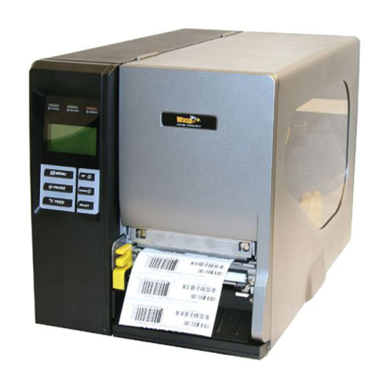
2.2 Printer Overview 2.2.1 Front View 1. LED indicators 2. LCD display 3. Front panel buttons 4. Paper exit chute 5. Lower front cover 6. Printer right side cover... -
Page 8: Interior View
2.2.2 Interior view 1. Ribbon rewind spindle 2. Ribbon release button 3. Ribbon guide plate 4. Print head 5. Platen roller 6. Print head release lever 7. Media guide bar 8. Label roll guard 9. Label supply spindle 10. Ribbon supply spindle 11. -
Page 9: Rear View
Note: 3. USB interface 1. SD card slot, Ethernet interface and PS/2 interface are standard 4. RS-232C interface interfaces for WPL610 model, but optional for WPL608 model. 5. Power jack socket 6. GPIO interface *7. SD card slot 8. Ethernet interface 9. -
Page 10: Operator Controls
2.3 Operator Controls 2.3.1 Front Panel Display LED indicators LCD display Front panel buttons 2.3.2 LED Indicators Status Indication The printer power is turned off The printer power is turned on Printer is ready Pause Blinking Downloading data into printer. Printer is ready "CARRIAGE OPEN"... -
Page 11: Front Panel Keys
2.3.3 Front Panel Keys Keys Function 1. Enter the menu 2. Exit from a menu or cancel a setting and return to the previous menu Pause/Resume the printing process Advance one label Scroll up the menu list Scroll down the menu list Enter/Select cursor located option 2.4 Setting Up the Printer 1. -
Page 12: Installation Of Ribbon
2.5 Installation of Ribbon 2.5.1 Loading Ribbon 1. Lift the right side printer cover to open it. 2. Push the print head release lever to open the print head mechanism. 3. Install the ribbon onto the ribbon supply spindle. 4. Thread the ribbon through the ribbon sensor slot and then through the open space in between the print head and platen. -
Page 13: Ribbon Sensor
Ribbon Ribbon sensor 5. Wrap the ribbon onto the ribbon rewind spindle, keeping the ribbon flat and without wrinkles. 6. Wind the ribbon clockwise about 3~5 rotations onto the ribbon rewind spindle until it is smooth and properly stretched. 7. Close the print head mechanism making sure the latches are engaged properly. - Page 14 Loading path for ribbon...
-
Page 15: Remove Used Ribbon
2.5.2 Remove Used Ribbon 1. Cut the ribbon between ribbon guide plate and the ribbon rewind spindle. 2. Push the ribbon release button to release the ribbon on the ribbon rewind spindle. 3. Then, slide off the ribbon from ribbon rewind spindle and discard. -
Page 16: Installation Of Media
2.6 Installation of Media 2.6.1 Loading Roll Labels 1. Lift open printer right side cover. 2. Push the print head release lever to open the print head mechanism. 3. Move the label roll guard horizontally to the end of label spindle then flip down the label roll guard. 4. - Page 17 5. Pull label roll leading edge forward through the media guide bar, damper, media sensor and place the label leading edge onto the platen roller. Media sensor Media guide bar Internal rewind (Option) Media sensor Damper Label guide 6. Adjust the label guide to fit the width of the label.
- Page 18 7. Close the print head mechanism making sure the latches are engaged properly. 8. Using the front display panel, set the media sensor type and calibrate the selected sensor. (Please refer to section 3.1.2) Note: Please calibrate the gap/black mark sensor when changing media. Loading path for roll labels...
-
Page 19: Loading Fan-Fold Labels
2.6.2 Loading Fan-fold Labels Fan-fold media feeds through either the bottom or rear external label entrance chute. 1. Lift open printer right side cover. 2. Push the print head release lever to open the print head mechanism. 3. Insert the fan-fold media through the bottom or rear external label entrance chute. 4. -
Page 21: Loading Media In Peel-Off Mode (Option)
2.6.3 Loading Media in Peel-off Mode (Option) 1. Lift open printer right side cover. 2. Push the print head release lever to open the print head mechanism. 3. Move the label roll guard horizontally to the end of label spindle then flip down the label roll guard. 4. - Page 22 12. Lift up the peel-off roller release lever and close the print head mechanism. 13. Rotate the peel-off sensor toward the paper exit chute. Peel-off sensor 14. Peeling will automatically start. Press the FEED button to test. Liner Label Note: Please calibrate the gap/black mark sensor when changing media.
-
Page 23: Remove Liner From Internal Rewind (Option)
2.6.4 Remove Liner from Internal Rewind 1. Cut the liner between peel-off roller and the internal rewind spindle. 2. Push the liner release button to release the liner on the internal rewind spindle. 3. Then, slide off the liner from internal rewind spindle and discard. -
Page 24: Loading Media In Rewind Liner With Label Mode (Option)
2.6.5 Loading Media in Rewind Liner with Label Mode (Option) This mode can rewind the media including liner and label on the rewind spindle. 1. Lift open the printer’s right side cover. 2. Insert the supply holder guide and paper core into the internal rewind for 1” core label roll. Insert the supply holder guide, 3”... - Page 25 Supply holder guide 7. Using the LCD panel set the media sensor type and calibrate the selected sensor. (Please refer to section 3.1.2) Note: Please calibrate the gap/black mark sensor when changing media.
-
Page 26: Remove Labels From Internal Rewind (Option)
2.6.6 Remove Labels from Internal Rewind (Option) 1. Slide off the labels with supply holder guides from the internal rewind spindle. Supply holder guides... -
Page 27: Adjustment Knob
2.7 Adjustment Knob 2.7.1 Print head Pressure Adjustment Knob Print head pressure adjustment knobs The print head pressure adjustment knob has 5 levels of adjustment. Because the printer’s paper alignment is to the left side of the mechanism, different media widths require different pressure to print correctly. - Page 28 Caution: Incorrectly adjusting these knobs can lead to poor print quality and may cause damage to the printer. Proceed with caution. The print head burn line default is set for general purpose printing media (plain paper and paper thickness less than 0.20mm). The adjustment knobs default position is screwed clockwise to the end of thread.
-
Page 29: Menu Function
3. Menu Function Main Menu Overview Main Menu Setup F ile Manager Diagnostics Language Serv ice Exit ↓ ↓ ↓ ↓ ↓ Printer Setup File List Print Config. English Initialization ↓ ↓ ↓ ↓ ↓ Avail. Sensor Dump Mode Chinese(TC) Mileage Info. -
Page 30: Setup Menu Overview
3.1 Setup Menu Overview Setup Printer Setup Sensor Serial Comm. Ethernet Exit ↓ ↓ ↓ ↓ TSPL2 Status Baud Rate Status ↓ ↓ ↓ ↓ Z PL2 Calibration Parity Configure ↓ ↓ ↓ ↓ Exit Exit Data Bits Exit ↓ Stop Bit(s) ↓... -
Page 31: Printer Setup
3.1.1 Printer Setup Printer Setup TSPL2 Speed Density Direction Print Mode Offset Shift X Shift Y Reference X Reference Y Code Page Country Exit ↓ ↓ ↓ ↓ ↓ ↓ ↓ ↓ ↓ ↓ None +000~- +000~-000 +000~-000 000~999 000~999 Batch Mode Peeler Mode Cutter Mode... - Page 32 3.1.1.1 Speed: Print Setup 1/12 Speed > Speed Density Direction Use this option to setup print speed. The available print speed is between 4~12 ips and each increament/decreament is 1 ips. The default print speed is 6 ips. Press the key to raise the print speed, and press the key to decrease print speed.
- Page 33 DIRECTION 0 DIRECTION 1 Note: If printing from enclosed software/driver, the software/driver will send out the command, which will overwrite the setting selection made on the front panel. 3.1.1.4 Print Mode: (None/Batch Mode/Peeler Mode/Cutter Mode/Cutter Batch) Print Setup 4/12 Print Mode Density >...
-
Page 34: Print Mode
command, which will overwrite the setting set from the front panel. 3.1.1.5 Offset: Print Setup 5/12 Direction Offset Print Mode +000 > Offset This option is used to fine tune media stop location. Press the button to move the cursor from left digit to right digit, and press the button to set the value from “+”... - Page 35 REFERENCE command, which will overwrite the setting set from the front panel. 3.1.1.7 Code Page: Code Page 11/41 Print Setup 10/12 > Reference X Reference Y > Code Page Use this option to set the code page of international character set. For more information about code page, please to refer the programming manual.
-
Page 36: Code Page
1258 Vietnam ISO Code Page ISO Code Page International code page International code page name number Character Set Character Set 8859-1 Latin 1 8859-7 Greek 8859-2 Latin 2 8859-9 Turkish 8859-3 Latin 3 8859-10 Latin 6 8859-4 Baltic 8859-15 Latin 9 8859-5 Cyrillic 3.1.1.8 Country:... -
Page 37: Sensor
3.1.2 Sensor Sensor Status Calibration Exit 3.1.2.1 Status This function is available to check the printer’s sensor status. When enter the [Status] option, you will see following message. Paper Len. Gap Size Intensity Ref. Level 3.1.2.2 Calibration This option is used to set the media sensor type and calibrate the selected sensor. We recommend you calibrate the sensor before printing when changing the media. - Page 38 A. Gap Mode Calibration Gap Mode > Gap Mode > Automatic Bline Mode Manual Cont. Mode Pre-Printed Press the buttons to scroll the cursor to the media type and press the button to enter the sensor calibration mode. Note: If printing from enclosed software/driver, the software/driver will send out the GAP or BLINE command, which will overwrite the sensor type setting set from the front panel.
- Page 39 3. Open the print head mechanism, put Gap Mode the label backing (liner) under the media sensor. Press the Scan Backing button to set the value into the printer. Intensity Ref. Level Media sensor Label backing (liner) 4. Then, put the label with liner under the Gap Mode media sensor.
- Page 40 1. Press the button to move the cursor from left digit to right digit, and press the button to set Paper Len. the value from “0” to “9” and the “dot/ 00812 dot mm/ inch”. Press the button to set the paper length into the printer.
- Page 41 B. Bline Mode Calibration Bline Mode Gap Mode > Automatic > Bline Mode Manual Cont. Mode Pre-Printed Press the buttons to scroll the cursor to the sensor type. Press the button to enter the black-mark sensor calibration mode. B-1 Automatic When enter the [Automatic] option, you will see the following message and the printer will feed the black mark label to calibrate the sensor sensitivity automatically.
- Page 42 3. Open the print head mechanism, put Bline Mode the black mark under the media sensor. Press the button Scan Mark to set the value into the printer. Intensity Ref. Level Media sensor Black mark 4. Then, put the label without black mark Bline Mode under the media sensor.
- Page 43 1. Press the button to move the cursor from left digit to right digit, and press the button to set Paper Len. the value from “0” to “9” and the “dot/ 00812 dot mm/ inch”. Press the button to set the paper length into the printer.
- Page 44 C. Cont. Mode Calibration Cont. Mode Bline Mode > Automatic > Cont. Mode Manual Exit Exit Press the buttons to scroll the cursor to the sensor type. Press the button to enter the black-mark sensor calibration mode. C-1 Automatic When you select the [Automatic] option, you will see the following message and the printer will calibrate the sensor sensitivity automatically.
-
Page 45: Serial Comm
3. The sensor calibration is complete. Cont. Mode Press the button the LCD screen will return to the previous Complete menu. Intensity Ref. Level 3.1.3 Serial Comm. Seria l Comm. Baud Ra te Parity Data Bits Stop Bit(s) Exit ↓ ↓... -
Page 46: Baud Rate
3.1.3.1 Baud Rate Serial Comm. Baud Rate > Baud Rate > 9600 bps Parity 19200 bps Data Bits 38400 bps This option is used to set the RS-232 baud rate. The default setting is 9600 bps. Press buttons to select the different baud rate and press button to set the value into printer. - Page 47 3.1.3.4 Stop Bit Serial Comm. Stop Bit(s) Parity > Data Bits > Stop Bit(s) Exit This option is used to set the RS-232 Stop Bits. The default setting is “1” stop bit. Press buttons to select the different Stop Bits and press button to set the value into printer.
-
Page 48: Ethernet
3.1.4 Ethernet Use this menu to configure internal Ethernet configuration check the printer’s Ethernet module status, and reset the Ethernet module. This function is available on the LCD display when Ethernet card is installed. Press the buttons to select the different options and press button to enter the option. - Page 49 3.1.4.1.2 MAC Ethernet Status MAC Address > Status IP Address 001B82-FF0918 Configure > Exit Exit The MAC address information will be shown on the LCD display. Please press button to return to the previous menu. 3.1.4.2 Configure: (DHCP / Static IP) Use this menu to set the printer's DHCP and Static IP.
- Page 50 3.1.4.2.2 Static IP Use this menu to set the printer's IP address, subnet mask and gateway. Ethernet Configure Status DHCP > Configure > Static IP Exit Exit Press buttons to select the different options and press button to enter the option. Press key to cancel the setting and return to the previous menu.
-
Page 51: File Manager
3.2 File Manager This feature is used to check the printer available memory and file list. File Mana ger File List Avail. Memory Del. All Files Exit ↓ ↓ DRAM DRAM ↓ ↓ FLASH FLASH ↓ ↓ CARD CARD ↓ ↓... -
Page 52: Avail. Memory
3.2.2 Avail. Memory Use this menu to show available memory space. File Manager Avail. Memory File List DRAM: 256 KB > Avail. Memory FALSH: 6656 KB Del. All Files CARD: 0 KB 3.2.3 Del. All Files Use this menu to delete all files. Press button to delete all files in the device. -
Page 53: Diagnostics
3.3 Diagnostics Diagnostics Print Config. Dump Mod e Rotate Cutter Exit 3.3.1 Print Config. This feature is used to print current printer configuration to the label. On the sconfiguration printout, there is a print head test pattern, which is useful for checking if there is any dot damage on the print head heater element. -
Page 54: Dump Mode
3.3.2 Dump Mode Captures the data from the communications port and prints out the data received by printer. In the dump mode, all characters will be printed in 2 columns as following. The left side characters are received from your system and right side data are the corresponding hexadecimal value of the characters. It allows users or engineers to verify and debug the program. -
Page 55: Rotate Cutter
3.3.3 Rotate Cutter In case paper is jammed in the cutter, this feature can rotate the cutter blade forward or backward, which is helpful to remove the jammed paper from the cutter. Diagnostics Fwd. Print Config. DOWN: Rev. Dump Mode >... -
Page 56: Service
Note : When printer initialization is done, please calibrate the gap or black mark sensor before printing. Parameter Default setting WPL610: 6 IPS (152 mm/sec) Speed WPL608:4 IPS (101.6 mm/sec) Density Label width 4.00"(101.6mm) Label height 4.00"(101.6mm) Gap sensor Sensor type 0.12"(3.0mm) -
Page 57: Mileage Info
Bline sensor sensitivity 2 (Will be reset. Need to re-calibrate the gap) Language English DHCP IP address 3.5.2 Mileage Info. Use this option to check the printed mileage (displayed in meter). Service Mileage:(m) Initialization 4016 > Mileage Info. Labels: (pcs.) Exit 51698... -
Page 58: Troubleshooting
The following guide lists the most common problems that may be encountered when operating this bar code printer. If the printer still does not function after you have tried all of these suggested solutions, please Wasp Customer Server for assistance. - Page 59 is not pin to pin connected. connected. - Check the baud rate setting. The default baud rate setting of printer is 9600,n,8,1. * If using the Ethernet cable, - Check if the Ethernet RJ-45 connector green LED is lit on.. - Check if the Ethernet RJ-45 connector amber LED is blinking.
- Page 60 adjustment knob has been adjust to index “5” and the poor print quality is still at the left side of the printout, please adjust the pressure adjustment knob to index “1” and use the Z-axis adjustment knob to fine tune the pressure.
- Page 61 * Set the correct label size. * Wrong label size setup. The left side printout * Press [MENU] [SELECT] x 3 [DOWN] x 5 * The parameter Shift X in LCD menu is [SELECT] to fine tune the parameter of Shift position is incorrect incorrect.
-
Page 62: Mechanism Fine Adjustment To Avoid Ribbon Wrinkles
4.2 Mechanism Fine Adjustment to Avoid Ribbon Wrinkles This printer has been fully tested before delivery. There should be no ribbon wrinkle present on the media for general-purpose printing application. Ribbon wrinkle is related to the media thickness, print head pressure balance, ribbon film characteristics, print darkness setting…etc. - Page 63 adjustment. adjustment. 1. Decrease the right side print head pressure 1. Decrease the left side print head pressure adjustment knob setting 1 level per each adjustment knob setting 1 level per each adjustment then print the label again to check if adjustment then print the label again to check if wrinkle is gone.
-
Page 64: Maintenance
5. Maintenance This chapter provides information on the proper cleaning tools and methods to maintain your printer. 1. Please use one of following materials to clean the printer. Cotton swab (Head cleaner pen) Lint-free cloth Vacuum / Blower brush 100% ethanol 2. - Page 65 Please use 100% Ethanol. DO NOT use medical alcohol, which may damage the printer head. Regularly clean the print head and supply sensors when installing a new ribbon to maintain optimal printer performance and extend the printer life.
Need help?
Do you have a question about the WPL608 and is the answer not in the manual?
Questions and answers