Wasp WPL205 User Manual
Direct thermal bar code printer
Hide thumbs
Also See for WPL205:
- User manual (9 pages) ,
- Comparison chart (1 page) ,
- Quick start manual (2 pages)
Table of Contents
Advertisement
Quick Links
Advertisement
Table of Contents

Related Manuals for Wasp WPL205


Summary of Contents for Wasp WPL205
- Page 1 WPL205 DIRECT THERMAL BAR CODE PRINTER USER’S MANUAL © 2007 Wasp Technologies...
-
Page 2: Table Of Contents
Table of Contents ........................1 OPYRIGHT ECLARATION .............................1 OMPLIANCES 2. Getting Started ........................2 2.1 Unpacking and Inspection ..................2 2.2 Equipment Checklist....................2 2.3 Printer Parts......................3 2.3.1 Front View ....................... 3 2.3.2 Rear View......................3 3.1 Setting Up the Printer ..................... 4 3.2 Loading Label Stock .................... -
Page 3: Copyright Declaration
Information in this subject to change without notice and does not represent a commitment on the part of Wasp Barcode Technologies. No part of this manual may be reproduced or transmitted in any form by any means, for any purpose other than the purchas100er’s personal use, without the expressed written permission of Wasp Barcode Technologies. -
Page 4: Getting Started
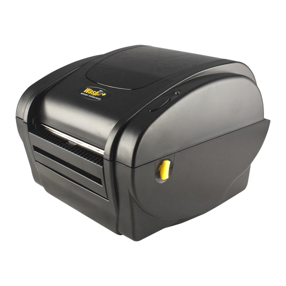
1. Introduction Thank you for purchasing the WASP WPL205 Direct Thermal Bar Code Printer. This printer provides both thermal transfer and direct thermal printing at user-selectable speeds of: 2.0, 3.0, 4.0 or 5.0 inches per second. It accepts roll feed, die-cut, and fan-fold labels for thermal transfer and direct thermal printing. -
Page 5: Printer Parts
2.3 Printer Parts 2.3.1 Front View Clear Window Top Cover LED Indicator Feed Button Label Opening Top Cover Open Lever Backing Paper Opening Front Panel 2.3.2 Rear View 1. USB Interface 2. Centronics Interface 3. RS-232C DB-9 Interface 4. Power Jack 5. -
Page 6: Setting Up The Printer
3 Setup 3.1 Setting Up the Printer 1. Place the printer on a flat, secure surface. 2. Make sure the power switch is off. 3. Connect the printer to the computer with the Centronics or USB cable. 4 Plug the DC power cord into the power jack at the rear of the printer, and then plug the AC power cord into a properly grounded receptacle. -
Page 7: Loading Label Stock
3.2 Loading Label Stock 1. Insert a 1” label spindle into a paper roll (If your paper core is 1 inch, remove the 1.5 inch core adapter from the fixing tab). Label Roll 1.5” Core Adapter Fixing Tab Printing Side Face up 1”... -
Page 8: Peel-Off Installation Assembly (Option)
6. Close the printer cover slowly and make sure the cover locks levers securely. Note: Failure to securely close and lock the cover will result in poor print quality. Peel-Off Installation Assembly (Option) Open the top cover. Unscrew the 6 screws in the lower inner cover. Screws Screws... - Page 9 Turn the printer upside down. Unscrew the 2 screws in the lower inner cover. Remove the screw Remove the screw Remove the screw at memory card cover. Screw Hold the lower cover and lift up the top cover opening levers to separate the lower inner cover from the lower cover.
- Page 10 Lower inner cover Lower cover Thread the harness red connector through the cable hole at the front side of the lower inner cover. Plug the red peel-off module harness connector at location JP17 on the main board. Place the lower inner cover on the lower cover. Install the peel-off module to the lower inner cover slot.
-
Page 11: Loading Label For Peel-Off Mode (Option)
3.4 Loading Label for Peel-off Mode (Option) 1. Open the peel-off module by pulling it out. Peel-off Roller Peel-off Panel 2. Thread the label, printing side facing up, through the label guides and place it on top of the platen. 3. -
Page 12: External Label Roll Mount Installation (Option)
3.5 External Label Roll Mount Installation (Option) 1. Attach an external label roll mount on the bottom of the printer. 2. Install a roll of label on the external label roll mount. Label External Label Roll Mount 3. Feed the label to the external label feed opening through the rear label guide. External Label Feed Opening Rear Label Guide... -
Page 13: Power On Utilities
4. Power on Utilities There are six power-on utilities to set up and test printer hardware. These utilities are activated by pressing FEED button and by turning on the printer power simultaneously. The utilities are listed as below: Gap/Black Mark sensor calibration Gap/black mark sensor calibration, Self-test and Dump mode Printer initialization Black mark sensor calibration... -
Page 14: Gap/Black Mark Calibration, Self-Test, Dump Mode
4.2 Gap/Black Mark Calibration, Self-test, Dump Mode While calibrating the gap/black mark sensor, the printer will measure the label length, print the internal configuration (self-test) and then enter the dump mode. Follow the steps as below. 1.Turn off the power switch. 2. - Page 15 Self-test The printer will print the printer configuration after gap/black mark sensor calibration. The self-test printout can be used to check if there is any dot damage on the heater element, printer configurations and available memory space. Print head check pattern Firmware version Firmware checksum Printed mileage (meter)
-
Page 16: Dump Mode
Dump mode The printer will enter dump mode after printing printer configuration. In the dump mode, all characters will be printed in 2 columns as shown below. The left side characters are received from your system and right side data are the corresponding hexadecimal value of the characters. -
Page 17: Printer Initialization
(5 blinks) solid green Printer configuration will be restored to defaults as outlined below after initialization. Parameter Default setting Speed WPL205, 127 mm/sec (5 ips) Density Label Width 4.25” (108.0 mm) Label Height 2.5” (63.4 mm) Media Sensor Type... -
Page 18: Black Mark Sensor Calibration
4.4 Black Mark Sensor Calibration Set black mark sensor as media sensor and calibrate the black mark sensor. Follow the steps below. 1. Turn off the power switch. 2. Press and hold the Feed button while turning the power back on. 3. -
Page 19: Maintenance
5. Maintenance 5.1 Cleaning Use one or more of the following supplies: Cotton swab Lint-free cloth Vacuum 100% ethanol The cleaning process is described below: Printer Part Method Printer Head 1. Always turn off the printer before cleaning the print head. 2. -
Page 20: Troubleshooting
6. Troubleshooting This section lists the common problems that you may encounter when operating the printer. 6.1 LED Status LED Status / Color Printer Status Solution Number Solid Green Flash Green Paused Flash Red Stopped No power. Turn on the power switch. Check if the green LED is lit on power supply. -
Page 21: Print Quality
6.2 Print Quality Continuous feeding labels The printer setting may go wrong. Please do the Initialization and Gap/Black Mark Calibration. No print on the label Is the label loaded correctly? Follow the instructions in Loading the Paper. Poor print quality Top cover is not closed properly. -
Page 22: Specifications
7. Specifications 7.1 Printer Specifications Item Specifications Mechanism Resolution 203 dpi. Max. Print Width 108 mm. Max. Print Length 1000 mm ( 39” ). Printing Speed 2, 3, 4 and 5 ips selectable. 2, 3 ips selectable with peeler function. Printing Method Direct thermal printing. -
Page 23: Label Stock Specifications
Command Set Environment Temperature: 5℃ ~ 40℃. Operation Relative Humidity: 25% ~ 85% (Non Condensing). Temperature: -40℃ ~ 60℃. Storage Relative Humidity: 10% ~ 90% (Non Condensing). 7.2 Label Stock Specifications Item Specification Type Label (Continuous , Die-cut , Fan-fold). Wound Type Outside wound. -
Page 24: Led And Button Operation
8. LED and Button Operation 8.1 LED LED Color Description Green/ Solid This illuminates that the power is on and the device is ready to use. Green/ Flash This illuminates that the system is downloading data from PC to memory and the printer is paused. Amber This illuminates that the system is clearing data from printer. - Page 25 Gap/Black Mark Sensor 1.Turn off the power switch. Calibratio, Label Length 2. Hold on the button then turn on the power switch. Measurement, Self 3. Release the button when LED becomes amber and blinking. (Any amber Test and enter Dump will do during the 5 blinks).
- Page 26 Gap Sensor Calibration 1. Turn off the power switch. 2. Hold on the button then turn on the power switch. 3. Release the button when LED turns red/amber after 5 green/amber blinks. (Any red/amber will do during the 5 blinks). The LED color will be changed as following: Amber red (5 blinks)
Need help?
Do you have a question about the WPL205 and is the answer not in the manual?
Questions and answers