Table of Contents
Advertisement
Quick Links
Advertisement
Table of Contents

Related Manuals for AXIOMTEK IPC920 Series


Summary of Contents for AXIOMTEK IPC920 Series
- Page 1 IPC920 series Industrial Computers User’s Manual...
-
Page 2: Disclaimers
Axiomtek reserves the right to change or revise this document and/or product at any time without notice. No part of this document may be reproduced, stored in a retrieval system, or transmitted, in any form or by any means, electronic, mechanical, photocopying, recording, or otherwise, without the prior written permission of Axiomtek Co., Ltd. -
Page 3: Safety Precautions
Safety Precautions Before getting started, please read the following important safety precautions. The IPC920 Series does not come equipped with an operating system. An operating system must be loaded first before installing any software into the computer. Be sure to ground yourself to prevent static charge when installing the internal components. Use a grounding wrist strap and place all electronic components in any static-shielded devices. -
Page 4: Classification
Classification Degree of production against electric shock: not classified Degree of protection against the ingress of water: none Equipment not suitable for use in the presence of a flammable anesthetic mixture with air or with oxygen or nitrous oxide. Mode of operation: Continuous Type of protection against electric shock: Class I equipment General Cleaning Tips You may need the following precautions before you begin to clean the computer. -
Page 5: Cleaning Tools
Cleaning Tools Although many companies have created products to help improve the process of cleaning your computer and peripherals users can also use household items to clean their computers and peripherals. Below is a listing of items you may need or want to use while cleaning your computer or computer peripherals. Keep in mind that some components in your computer may require designated products for cleaning. -
Page 6: Scrap Computer Recycling
Scrap Computer Recycling Please inform the nearest Axiomtek distributor as soon as possible for suitable solutions in case computers require maintenance or repair; or for recycling in case computers are out of order or no longer in use. Trademark Acknowledgments Axiomtek is a trademark of Axiomtek Co., Ltd. -
Page 7: Table Of Contents
Table of Contents Disclaimers ......................ii Safety Precautions ....................iii Classification ......................iv General Cleaning Tips ..................iv Cleaning Tools ....................... v Scrap Computer Recycling ................... vi SECTION 1 INTRODUCTION................. 1 General Description ................1 System Specifications ............... 2 1.2.1 System Features .................... - Page 8 Installing the NVMe SSD, Mini Card & M.2 key E Module ....37 Using the Cable Tie ................40 2.10 Mounting ................... 42 SECTION 3 AMI BIOS UTILITY ..............47 Starting ..................... 47 Navigation Keys ................48 Main Menu ..................49 Advanced ..................
-
Page 9: Section 1 Introduction
For operation systems, the IPC920 series not only supports Windows® 11 64-bit, Windows® 10 64-bit and Ubuntu, but also supports embedded OS. The IPC920 Series supports two hard-drive bays to make it easy for customers to install and maintain the system. -
Page 10: System Specifications
IPC920 Series User’s Manual System Specifications 1.2.1 System Features ntelligent power management: ⚫ - Ignition - USB power on/off control Supports Intel® RAID (R680E) ⚫ Easy expansion via flexible I/O window ⚫ Supports connectors with pull-resistance design ⚫ Optional din-rail kit, bookshelf kit and wall mount kit ⚫... -
Page 11: Specification
IPC920 Series User’s Manual 1.2.3 Specification IPC920-R-F1 IPC920-R-F1E IPC920-H-F1 IPC920-H-F1E System chipset R680E H610E AMI BIOS with Smart View and Customer CMOS Backup BIOS System memory 2x DDR5 4800/4000 un-buffered SO-DIMM, max up to 64GB 2 x RJ45 2.5GbE Intel I226-V Ethernet 1 x RJ45 1GbE Intel I219-LM;... - Page 12 IPC920 Series User’s Manual IPC920-H-F1, IPC920-R-F1: IEC 60068-2-64 (with SSD: 3Grms STD, random, 5 to 500 Hz, 1 hr/axis) Vibration IPC920-H-F1E, IPC920-R-F1E: IEC 60068-6-4 (W/SSD: 1Grms STD, random, 5-500 Hz, 1 hr/axis) Shock IEC 60068-2-27 (with SSD: 50G, half sine, 11 ms duration) IPC920-H-E, IPC920-R-E: 83.5 x 192 x 230 mm...
-
Page 13: Operating Temperature
IPC920 Series User’s Manual 1.2.4 Operating Temperature Below is a list of IPC920 series operating temperature w/ Intel® Core™ processor and industrial ⚫ wide-temp SSD. Operating Performance- Efficient-core Generation Proc No WATT Temperature core base base frequency frequency (0.7 m/s air flow) -
Page 14: Certification
IPC920 Series User’s Manual Note: If the operating temperature is above 35°C, it is recommended to use a wide temperature SSD on the device. 1.2.5 Certification CE (EN 61000-6-4, EN 61000-6-2) ⚫ ⚫ Note: All specifications and images are subject to change without notice. -
Page 15: System Dimensions
IPC920 Series User’s Manual System Dimensions The following diagrams show you dimensions and outlines of theIPC920 Series. IPC920-R-F1 / IPC920-H-F1 Introduction... - Page 16 IPC920 Series User’s Manual IPC920-R-F1E / IPC920-H-F1E Introduction...
-
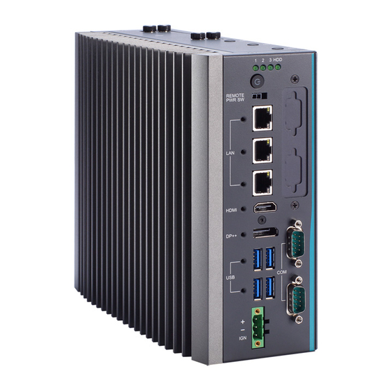
Page 17: System Outlets
IPC920 Series User’s Manual System Outlets The following figures show locations of the IPC920 series system outlets. Introduction... - Page 18 IPC920 Series User’s Manual Mark Description 2 x 2.5” HDD/SSD tray Remote power switch 2 x 2.5GbE Intel I226-V 1GbE Intel I219-LM HDMI 1.4b with 4096 x 2160 resolution DP++ 1.2 with 4096 x 2160 resolution 2 x USB3.2 Gen2x1 10G 2 x USB3.2 Gen2x1 10G (R680E) or...
-
Page 19: Packing List
⚫ Foot pad x 4 ⚫ CPU Thermal grease x 1 ⚫ Terminal block x 1 ⚫ Remote power switch cable x1 ⚫ If you cannot find this package or any items are missing, please contact Axiomtek distributors immediately. Introduction... -
Page 20: M/B Block Diagram
IPC920 Series User’s Manual M/B Block Diagram The following diagram shows you the M/B block diagram of PSB526. Introduction... -
Page 21: Switch & Led Settings
IPC920 Series User’s Manual Switch & LED Settings Properly configure switch settings on the PSB526 to meet your application purpose. Below you can find a summary table of all Switches and onboard default settings. 1.7.1 Restore BIOS Optimal Defaults (SW1) Open system cover, then press touch switch for 5 seconds to restore BIOS optimal defaults. -
Page 22: Power On/Off Button (Sw2) & Led (Led1)
IPC920 Series User’s Manual 1.7.2 Power On/OFF Button (SW2) & LED (LED1) The power button is on the I/O side. It allows users to control IPC920 power on/off, The LED displays the current status, refer to the table below for information. -
Page 23: Connectors
IPC920 Series User’s Manual Connectors Connectors connect the board with other parts of the system. Loose or improper connection might cause problems. Make sure all connectors are properly and firmly connected. Here is a table summarizing all connectors on the board. -
Page 24: Com Port Wafer Connector (Cn1, Cn3)
IPC920 Series User’s Manual 1.8.2 COM port wafer connector (CN1, CN3) The pin assignments of RS-232/422/485 are listed in the below table. Set COM signals to operate in RS-232/422/485 by BIOS. Supports High-Speed Mode 115.2 Kbps, up to 1.5 Kbps... -
Page 25: Digital I/O Connector (Cn4, Cn5)
IPC920 Series User’s Manual 1.8.3 Digital I/O connector (CN4, CN5) This header (5x2-pin p=2.00mm) is for digital I/O interface. The voltage of TTL is 5V ⚫ The programming is as follow: ⚫ - I/O sink current is 8~10mA - Input/Output can be programmed... -
Page 26: Rj45 Lan Gigabit Ethernet (Cn9)
IPC920 Series User’s Manual 1.8.5 RJ45 LAN Gigabit Ethernet (CN9) The system has one RJ-45 connectors: CN9. Ethernet connection can be established by plugging one end of the Ethernet cable into this RJ-45 connector and the other end (phone jack) to a 1000/100/10-Base-T hub. -
Page 27: Dual Usb 3.2 Type-A Connector (Cn11, Cn17)
IPC920 Series User’s Manual 1.8.7 Dual USB 3.2 Type-A connector (CN11, CN17) The Universal Serial Bus connectors are compliant with USB3.2 and ideal for installing USB peripherals such as scanners, cameras and USB devices. H610E=USB3.2 GEN1 (5Gbps) + USB3.2 GEN2 (10Gbps) R680E=USB3.2 GEN2 (10Gbps) -
Page 28: Dp Connector (Cn20)
IPC920 Series User’s Manual 1.8.8 DP connector (CN20) The DP++ is a compact digital interface which is capable of transmitting high -definition video and high-resolution audio over a single cable. Signal Signal LANE 0 LANE 0# LANE 1 LANE 1#... -
Page 29: Sata Power Wafer Connector (Cn13, Cn14)
IPC920 Series User’s Manual 1.8.10 SATA power wafer connector (CN13, CN14) The SATA power connector is used for interfacing SATA 2.5" HDD/SSD power supply. Signal 1.8.11 SATA Connector (SATA1, SATA2) These Serial Advanced Technology Attachment (Serial ATA or SATA) connectors are used as high-speed SATA interfaces. -
Page 30: Key M 2280 Connector (Scn1)
IPC920 Series User’s Manual 1.8.12 M.2 Key M 2280 connector (SCN1) The M.2 2280 Key M NVM Express SSD for storage. Signal Signal Signal Signal +3.3V +3.3V PERn3 PERp3 LED_1# PETn3 +3.3V PETp3 +3.3V +3.3V PERn2 +3.3V PERp2 PETn2 PETp2... -
Page 31: Key E 2230 Connector (*Scn7)
IPC920 Series User’s Manual 1.8.13 M.2 Key E 2230 connector (*SCN7) SCN7 for PCI-Express and USB signals interface supported Key E ,type 2230. Signal Signal Signal Signal +3.3V USB_D+ +3.3V USB_D- CONNECTOR KEY CONNECTOR KEY CONNECTOR KEY CONNECTOR KEY CONNECTOR KEY... -
Page 32: Mini Card Connector (Scn8)
IPC920 Series User’s Manual 1.8.14 Mini card connector (SCN8) A PCI-Express Mini Card connector is located on the top side. It complies with PCI-Express Mini Card Spec. V1.2. Pins Signals Pins Signals WAKE# +3.3VSB No use +1.5V No use CLKREQ#... -
Page 33: Remote Power Switch Connector (Pwrbt1)
1.8.16 Riser card – EIO110 IPC920-R-F1E and IPC920-H-F1E have a riser module to support PCIe slots. Expansion Power Input Connectors (ATX1) This ATX1 connector for reserved uses. (Black color) Pins Signals +12V +12V Note: ATX1 is reserved, please contact Axiomtek before using it. Introduction... - Page 34 IPC920 Series User’s Manual This page is intentionally left blank. Introduction...
-
Page 35: Section 2 Hardware Installation
SECTION 2 HARDWARE INSTALLATION The IPC920 Series products are convenient for your various hardware configurations, such as CPU (Central Processing Unit), memory module, HDD (Hard Disk Drive) and PCIe/PCI card. Chapter 2 will show you how to install these hardware parts. -
Page 36: Procedure Of Installation
IPC920 Series User’s Manual Procedure of Installation This chapter will guide you on installing a processor. Step 1 Turn off the system. Step 2 Disconnect the power connector. Step 3 Loosen eight screws to remove the heatsink cover from the chassis. - Page 37 IPC920 Series User’s Manual Grasp the processor with the thumb and index fingers along the top and bottom edges. ➢ The socket will have cutouts for your fingers to fit into. Carefully place the processor into the socket vertically. ➢...
-
Page 38: Installing The Memory Module
IPC920 Series User’s Manual Installing the Memory Module Step 1 Paste the thermal pad on the bottom side of the module. Remember to remove the protective film from the thermal pad. Step 2 Turn off the system. Step 3 Disconnect the power connector. -
Page 39: Installing The Hard Disk Drive
IPC920 Series User’s Manual Installing the Hard Disk Drive The IPC920 series offers two convenient drive trays modules for users to install HDD/SSD. Please follow the steps to install: Step 1 Turn off the system. Step 2 Disconnect the power connector. -
Page 40: Installing The Flexible I/O
IPC920 Series User’s Manual Installing the flexible I/O The IPC920 provides a flexible I/O window for expansion. The procedures of installing I/O cable or module into system is instructed below. IPC920-R-F1 / IPC920-R-F1E IPC920-H-F1 / IPC920-H-F1E 2 x 8-bit programmable DIO 2 x 8-bit programmable DIO 2 x 2 USB 2.0... - Page 41 IPC920 Series User’s Manual Step 3 Complete the flexible I/O installation as the below procedure illustrates. IPC920-R-F1 / IPC920-H-F1 IPC920-R-F1E / IPC920-H-F1E Unscrew the four screws and Unscrew the four screw and separating the cover from the separate the cover from the expansion box.
-
Page 42: Installing Usb Dongle
IPC920 Series User’s Manual → Install flexible windows cover to Attach the flexible window cover to the main chassis. Then, chassis, then fasten all screws. insert and secure the expansion box into the main chassis The installation is complete using screws. Fasten four screws to fix the cover. -
Page 43: Installing Pcie Card
IPC920 Series User’s Manual Installing PCIe Card The IPC920-R-F1E and IPC920-H-F1E provide a PCIe x16 slot for expansion. The procedure of installing PCIe expansion card into system is instructed below. 2.7.1 Installing PCIe card Step 1 Turn off the system. -
Page 44: The Limitation Of An Add-On Card
IPC920 Series User’s Manual 2.7.2 The limitation of an add-on card The following figures show the limitation of an add-in card in different configuration. Slot (PCIe x16) Height length width 1-slot Note: Please note that above dimension is the maximum length for add-on card with I/O bracket. -
Page 45: Installing The Nvme Ssd, Mini Card & M.2 Key E Module
IPC920 Series User’s Manual Installing the NVMe SSD, Mini Card & M.2 key E Module The IPC920 comes equipped with a mini card slot, an optional M.2 key E/B slot and a M.2 key M slot for users to install wireless LAN cards and SSD. Please refer to the following instructions and illustrations for the installation of the wireless LAN and SSD. - Page 46 IPC920 Series User’s Manual Unscrew the four screws and separate the expansion box from the main chassis. Step 4 Please follow the steps below to install modules. M.2 key M Paste the thermal pad(2) on the bracket(1) and tear the protective cover.
- Page 47 IPC920 Series User’s Manual Tight the bracket. The installation is complete., ➢ Mini PCIe / M.2 key E Carefully insert the wireless LAN card into its designated slot on the motherboard. Gently press ➢ down until it clicks or locks into place.
-
Page 48: Using The Cable Tie
IPC920 Series User’s Manual Using the Cable Tie The IPC920 provides cable tie (1) and cable holder (2) for optional selection, using the cable tie, it helps you to ensure your I/O cable is secure. To use the cable tie, do the following: Step 1 Turn off the system. - Page 49 IPC920 Series User’s Manual Step 4 Attach the cable holder (2) to the I/O cable(s) and thread the cable tie (1) through the holder. (as shown in the illustration below in red rectangle) → Step 5 Open the latch (A) of cable holder and thread cable holder (B) through the latch (as shown below in read rectangle), tighten the cable holder to encircle the I/O cable(s).
-
Page 50: 2.10 Mounting
IPC920 Series User’s Manual 2.10 Mounting The IPC920 provides optional mount kits for different deployment field sites . DIN rail mount Note: The DIN rail kit can be installed in IPC920-R-F1 and IPC920-H-F1 only. Hardware Installation... - Page 51 IPC920 Series User’s Manual Bookshelf mount Note: The bookshelf mount kit can be installed in IPC920-R-F1 and IPC920-H-F1 only. Note: The IPC920-R(H)-F1 supports DIN rail kit, bookshelf kit or wall mount kit. Hardware Installation...
- Page 52 IPC920 Series User’s Manual Wall mount Hardware Installation...
- Page 53 IPC920 Series User’s Manual Hardware Installation...
- Page 54 IPC920 Series User’s Manual Note: The IPC920 supports any of din rail kit, bookshelf mount kit or wall mount kit. Hardware Installation...
-
Page 55: Section 3 Ami Bios Utility
IPC920 Series User’s Manual SECTION 3 AMI BIOS UTILITY The AMI UEFI BIOS provides users with a built-in setup program to modify basic system configuration. All configured parameters are stored in a 16MB flash chip to save the setup information whenever the power is turned off. This chapter provides users with detailed description about how to set up basic system configuration through the AMI BIOS setup utility. -
Page 56: Navigation Keys
IPC920 Series User’s Manual Navigation Keys The BIOS setup/utility uses a key-based navigation system called hot keys. Most of the BIOS setup utility hot keys can be used at any time during the setup navigation process. These keys include <F1>, <F2>, <Enter>, <ESC>, <Arrow>... -
Page 57: Main Menu
IPC920 Series User’s Manual Main Menu When you first enter the setup utility, you will enter the Main setup screen. You can always return to the Main setup screen by selecting the Main tab. System Time/Date can be set up as described below. The Main BIOS setup screen is shown below. -
Page 58: Advanced
IPC920 Series User’s Manual Advanced Advanced Menu ⚫ The Advanced menu also allows users to set configuration of the CPU and other system devices. You can select any of the items in the left frame of the screen to go to the sub menus: Smart Ignition Management ⚫... - Page 59 IPC920 Series User’s Manual *For Q670E platfomr Smart Ignition Configuration ⚫ Press Enter to access the sub-menu. Calculated based on the 24-hour military-time clock. AMI BIOS Utility...
- Page 60 IPC920 Series User’s Manual BIOS menu item Description Ignition Management Enabled Switch to ACC mode *Note: IGN signal will only be triggered when DCIN Terminal Block 4-Pin IGN is connected with VCC. Disabled Switch to AT mode *Note: System will be reset after Ignition Management setting has been changed and saved.
- Page 61 IPC920 Series User’s Manual Advance Setting Set system on/off timing and voltage threshold levels Save Settings Save the current settings Restore Factory Restores factory defaults to remove any incorrect or corrupt settings that Settings might have prevented the system from properly powering on/off.
- Page 62 IPC920 Series User’s Manual AMI BIOS Utility...
- Page 63 IPC920 Series User’s Manual BIOS menu item Description Activate Voltage Trigger The system only turns on when the voltage delivered by the power source is higher than the value you set here. The system will begin countdown stage once voltage drops below Low Voltage Trigger the value you set here.
- Page 64 IPC920 Series User’s Manual ACPI Settings ⚫ ACPI configuration can be configured in ACPI Settings. A description of the selected item appears on the right side of the screen. ACPI Sleep State ➢ Select the ACPI (Advanced Configuration and Power Interface) sleep state. Configuration options are Suspend Disabled and S3 (Suspend to RAM).
- Page 65 IPC920 Series User’s Manual Trusted Computing ⚫ Select Security Device Support to enable or disable the TPM function. TPM Device Selection ➢ Select TPM device: PTT: Intel® built-in TPM. Enables PTT in SkuMgr. dTPM: External extended Infineon’s TPM. Disables PTT in SkuMgr.
- Page 66 IPC920 Series User’s Manual Platform Misc Configuration ⚫ This screen allows you to set Platform Misc Configuration. Native PCIE Enable ➢ Enabled - Enable PCIE power saving function, Disabled - Disabled PCIE power saving function. Native ASPM ➢ Enabled - OS Controlled ASPM, Disabled - BIOS Controlled ASPM.
- Page 67 IPC920 Series User’s Manual CPU Configuration ⚫ This screen shows the CPU configuration, and you can change the value of the selected option. Hardware Prefetcher ➢ Turn on/off the MLC streamer prefetcher. Adjacent Cache Line Prefetch ➢ Turn on/off prefetching of adjacent cache lines.
- Page 68 IPC920 Series User’s Manual Active Efficient Cores ➢ Number of E-cores to enable in each processor package. Note: Number of P-Cores and E-cores are counted together. When both are {0,0}, P-code will enable all cores. Enable / Disable AES (Advanced Encryption Standard) Boot performance mode ➢...
- Page 69 IPC920 Series User’s Manual SATA Configuration ⚫ During system boot up, the BIOS automatically detects the presence of SATA devices. In the SATA Configuration menu, you can see the hardware currently installed in the SATA ports. SATA Controller(s) ➢ Enable or disable the SATA Controller feature. The default is Enabled.
- Page 70 IPC920 Series User’s Manual NVMe Configuration ⚫ This screen shows NVMe device information. AMI BIOS Utility...
- Page 71 IPC920 Series User’s Manual AMT Configuration ⚫ This screen displays Active Management Technology information. *For Q670 platform AMT BIOS Features ➢ Enable or disable Active Management Technology BIOS features. The default is Enabled. AMI BIOS Utility...
- Page 72 IPC920 Series User’s Manual F81966 Super IO Configuration ⚫ You can use this screen to select options for the Super IO Configuration and change the value of the selected option. A description of the selected item appears on the right side of the screen. For items marked with “”, please press <Enter>...
- Page 73 IPC920 Series User’s Manual Serial Port 1 Configuration ⚫ Use these items to set parameters related to serial port 1. Serial Port 1 ➢ This item allows you to use it as RS232/422/485. The default is RS232. AMI BIOS Utility...
- Page 74 IPC920 Series User’s Manual Hardware Monitor ⚫ This screen monitors hardware health status. This screen displays the temperature of system and CPU, cooling fans speed in RPM and system voltages (VCC_CPU, DDR, +12V, +5V and +3.3V). Note: Fan module is an option kit, fans speed will be displayed when it is installed in IPC962A and IPC964A.
- Page 75 IPC920 Series User’s Manual USB Configuration ⚫ This screen shows USB configuration. AMI BIOS Utility...
-
Page 76: Chipset Menu
IPC920 Series User’s Manual Chipset Menu The Chipset menu allows users to change the advanced chipset settings. You can select any of the items in the left frame of the screen to go to the sub menus: System Agent (SA) Configuration ⚫... - Page 77 IPC920 Series User’s Manual VT-d ➢ Check to enable VT-d function on MCH. Above 4GB MMIO BIOS assignment ➢ Enable/Disable above 4GB Memory Mapped IO BIOS assignment.This is enabled automatically when Aperture Size is set to 2048MB. AMI BIOS Utility...
- Page 78 IPC920 Series User’s Manual Graphics Configuration ⚫ This screen shows graphics configuration. Internal Graphics ➢ Keep IGFX enabled based on the setup options. AMI BIOS Utility...
- Page 79 IPC920 Series User’s Manual CPU PCI Express Root Port ⚫ This screen shows CPU PCI Express root port information. ASPM ➢ Set the ASPM Level:\nForce L0s - Force all links to L0s State\nForce L1 - Force all links to L1 State\nForce L0sL1 - Force all links to L0SL1 State\nDISABLE - Disables ASPM.
- Page 80 IPC920 Series User’s Manual PCH-IO Configuration ⚫ This screen allows you to set PCH parameters. PCI Express Configuration ➢ Configure PCIe Speed. HD Audio Configuration ➢ Enable or disable HD Audio. Wake on LAN Enable ➢ Enable or disable integrated LAN to wake the system.
- Page 81 IPC920 Series User’s Manual HD Audio Configuration ⚫ This screen shows HD Audio information. AMI BIOS Utility...
-
Page 82: 3.6 Security Menu
IPC920 Series User’s Manual 3.6 Security Menu The Security menu allows users to change the security settings for the system. Administrator Password ➢ This item indicates whether an administrator password has been set (installed or uninstalled). User Password ➢ This item indicates whether a user password has been set (installed or uninstalled). - Page 83 IPC920 Series User’s Manual Secure Boot ⚫ AMI BIOS Utility...
-
Page 84: Boot Menu
IPC920 Series User’s Manual Boot Menu The Boot menu allows users to change boot options of the system. Setup Prompt Timeout ➢ Set the number of seconds to wait for setup activation key. 65535(0xFFFF) means indefinite waiting. Bootup NumLock State ➢... -
Page 85: Save & Exit Menu
IPC920 Series User’s Manual Save & Exit Menu The Save & Exit menu allows users to load your system configuration with optimal or fail-safe default values. Save Changes and Exit ➢ When finishing the system configuration settings, select this option to leave Setup and return to Main Menu. - Page 86 IPC920 Series User’s Manual Save Changes ➢ When finishing the system configuration settings, select this option to save changes. Select Save Changes from the Save & Exit menu and press <Enter>. Select Yes to save changes. Discard Changes ➢ Select this option to quit Setup without making any permanent changes to the system configuration.
-
Page 87: Appendix Awatchdog Timer
IPC920 Series User’s Manual APPENDIX A WATCHDOG TIMER A.1 About Watchdog Timer Software stability is a major issue in most applications. Some embedded systems are not watched by an operator for 24 hours. It is usually too late to wait for someone to reboot when computer hangs. The systems need to be able to reset automatically when things go wrong. - Page 88 IPC920 Series User’s Manual int unit = 0; int WDTtimer = 0; if (hinstLibDLL == NULL) hinstLibDLL = LoadLibrary(TEXT("diodll.dll")); if (hinstLibDLL == NULL) //MessageBox("Load diodll dll error", "", MB_OK); if (hinstLibDLL) lpFnDll_Get_IO = (LPFNDLLGETIOSPACE)GetProcAddress(GetModuleHandle("diodll.dll"), "GetIoSpaceByte"); lpFnDll_Set_IO = (LPFNDLLSETIOSPACE)GetProcAddress(GetModuleHandle("diodll.dll"), "SetIoSpaceByte"); printf("Input Watch Dog Timer type, 1:Second ; 2:Minute :");...
- Page 89 IPC920 Series User’s Manual else if (unit == 2) //set WDT Timer lpFnDll_Set_IO(0x2e, 0xF6); lpFnDll_Set_IO(0x2f, WDTtimer); //set watchdog time unit to min lpFnDll_Set_IO(0x2e, 0xF5); WDTDATA = lpFnDll_Get_IO(0x2f); WDTDATA = setbit(WDTDATA, 3); lpFnDll_Set_IO(0x2f, WDTDATA); //start watchdog counting lpFnDll_Set_IO(0x2e, 0xF5); WDTDATA = lpFnDll_Get_IO(0x2f);...
- Page 90 IPC920 Series User’s Manual This page is intentionally left blank. Watchdog Timer...
-
Page 91: Appendix Bwake On Lan
IPC920 Series User’s Manual APPENDIX B WAKE ON LAN How to Set up Wake on LAN Please follow the following steps to set up Wake on LAN on Windows 11. Press “ ” w/ “S” or press “ ” on Windows desktop. - Page 92 IPC920 Series User’s Manual Wake On LAN...
- Page 93 IPC920 Series User’s Manual Select a LAN port (1) which will support “Wake on LAN”, then enable functionality you need under “Adapter Settings” (2) Press “Apply Changes” (3). **Please follow step 4 and step 5 to set the other LAN ports for “Wake on LAN”...
- Page 94 IPC920 Series User’s Manual Select “Open”. Wake On LAN...
- Page 95 IPC920 Series User’s Manual Press Power options →Change what the power button do 10. Remove “ ” from “Turn on fast startup”, the press “Save changes”. Reboot the system to enable the above settings. Installation is completed. Wake On LAN...
- Page 96 IPC920 Series User’s Manual This page is intentionally left blank Wake On LAN...
-
Page 97: Appendix Chdd Hot-Swappable
IPC920 Series User’s Manual APPENDIX C HDD HOT-SWAPPABLE HDD HOT-SWAPPABLE IPC920 offers two hot-swap 2.5” HDD or SSD, people can easy install and replace the storages by following steps. Using HDD hot-swappable function Step 1 Please press “Delete” after turn on the system, then following the path to enable the Hot Plug function. - Page 98 IPC920 Series User’s Manual Removing Hot-Swappable storage Step 1 Click “ “ Step 2 Select “Eject xxxx”. Step 3 Remove the HDD devic after “Safe To Remove Hardware” shown. HDD HOT-Swappable...
- Page 99 IPC920 Series User’s Manual Note: Please close the programs which are in using before removing the devices. HDD HOT-Swappable...
Need help?
Do you have a question about the IPC920 Series and is the answer not in the manual?
Questions and answers