Table of Contents
Advertisement
Quick Links
Advertisement
Table of Contents

Related Manuals for AXIOMTEK IPC974-519-FL


Summary of Contents for AXIOMTEK IPC974-519-FL
- Page 1 IPC974-519-FL Industrial and Fanless Computers User’s Manual...
- Page 2 Axiomtek does not make any commitment to update the information in this manual. Axiomtek reserves the right to change or revise this document and/or product at any time without notice.
-
Page 3: Safety Precautions
Safety Precautions Before getting started, please read the following important safety precautions. The IPC974-519-FL does not come equipped with an operating system. An operating system must be loaded first before installing any software into the computer. Be sure to ground yourself to prevent static charge when installing the internal components. -
Page 4: Classification
Classification Degree of production against electric shock: not classified Degree of protection against the ingress of water: IPX40 Equipment not suitable for use in the presence of a flammable anesthetic mixture with air or with oxygen or nitrous oxide. Mode of operation: Continuous Type of protection against electric shock: Class I equipment General Cleaning Tips You may need the following precautions before you begin to clean the computer . - Page 5 Cleaning Tools: Although many companies have created products to help improve the process of cleaning computers and peripherals, users can also use household items to clean their computers and peripherals. Below is a listing of items available for cleaning computers or computer peripherals. Keep in mind that some components in your computer may only be cleaned using a product designed for cleaning components of the same types.
-
Page 6: Scrap Computer Recycling
Scrap Computer Recycling Please inform the nearest Axiomtek distributor as soon as possible for suitable solutions in case computers require maintenance or repair; or for recycling in case computers are out of order or no longer in use. Trademark Acknowledgments Axiomtek is a trademark of Axiomtek Co., Ltd. -
Page 7: Table Of Contents
Table of Contents Safety Precautions ....................iii Classification ......................iv General Cleaning Tips ..................iv Scrap Computer Recycling .................. vi CHAPTER 1 INTRODUCTION ................1 General Description ................1 System Specifications ............... 2 1.2.1 Main CPU Board ....................2 1.2.2 I/O System ...................... - Page 8 Installing the WIFI Module ............... 48 Installing USB dongle kit ..............49 Installing foot pad ................50 Wall mounting .................. 51 CHAPTER 3 AMI BIOS UTILITY................53 Starting ..................... 53 Navigation Keys ................54 Main Menu ..................55 Advanced Menu ................56 Chipset Menu ...................
-
Page 9: Chapter 1 Introduction
Jumper Settings Connectors Package List General Description ® The IPC974-519-FL is a fanless system that supports the LGA1151 socket for Intel Xeon and 6 generation Core i7/i5/i3 processors. The IPC974-519-FL supports ® ® W indows 7 and W indows 10, with a rugged design that makes it suitable for the most endurable operation. -
Page 10: System Specifications
IPC974 Series User’s Manual System Specifications 1.2.1 Main CPU Board ® Socket LGA1151 for 6 Generation Intel Core i7/i5/i3 and Xeon processors, up to 80W. CPU support is listed as below. Core Thread Base frequency Processor i5-6400T 2.20 GHz 35 W i5-6500TE 2.30 GHz... -
Page 11: I/O System
IPC974 Series User’s Manual Features Fanless operation Compact & front IO design Supports four expansion slots DC to DC power supply; supports 24VDC (uMin=19V/uMax=30V) TPM2.0 Supports system power on delay function Supports Intel® RAID 0,1,5 1.2.2 I/O System ... - Page 12 IPC974 Series User’s Manual Expansion Slot 1 x on board full-size PCI Express Mini Card slot with USB/PCIe interface w/SIM slot AX96410: 1 PCIex16 + 3 PCIex4 AX96411: 1 PCIex16 + 1 PCIex4 + 2 PCI ℃...
- Page 13 IPC974 Series User’s Manual 1.2.3 System Specification Drive Capacity 1 x HDD drive bay (default, supports 2 x 2.5” HDD/SSD) 1 x HDD drive bay (optional, supports 2 x 2.5” HDD/SSD) (height 7mm or 9.5mm) Note: Since Gen. 2 SSD with JMicron controller has compatibility issue with Intel PCH, it is strongly recommended to use Gen.
- Page 14 IPC974 Series User’s Manual Storage Temperature -20℃ ~ 80℃ Humidity 10% ~ 90% (Non-condensing) Dimensions 188.14 mm (7.40”) (W) x 192 mm (7.54) (H) x 317 mm (12.46") (D) Note: All specifications and images are subject to change without notice. Note: The performance of the system could be adversely affected at an over spec operating temperature or with an unrecommended processor.
-
Page 15: M/B Block Diagram & System Dimensions
IPC974 Series User’s Manual M/B Block Diagram & System Dimensions The following diagrams show you M/B block diagram, system dimensions and outlines of the IPC974-519-FL. Introduction... - Page 16 IPC974 Series User’s Manual...
-
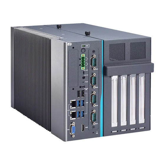
Page 17: Outlets
IPC974 Series User’s Manual Outlets The following figures show you outlets on the front and top panels of the IPC974-519-FL. Introduction... - Page 18 IPC974 Series User’s Manual No. Description Description 2 x Antenna opening 2-pin connector output for remote power on/off switch 1 x HDD drive bay(default, support 2 x USB 2.0 2 x 2.5” HDD/SSD) drive bay(optional, 1 x 10/100/1000Mbps ethernet(i211-AT) support 2 x 2.5” HDD/SSD) 2 x USB3.0 HDD access/power LED 1 x 10/100/1000Mbps ethernet(i219LM)
-
Page 19: Packing List
CPU grease x 1 Terminal block x 1 Remote switch cable x 1 Extension holder bracket kit x 1 If you cannot find this package or any items are missing, please contact Axiomtek distributors immediately. Introduction... -
Page 20: Jumper Settings
IPC974 Series User’s Manual Jumper Settings Properly configure jumper settings on the SBC87511/SBC87512 to meet your application purpose. Below you can find a summary table of all jumpers and onboard default settings. Note: How to setup Jumpers Illustrations below show that a cap on a jumper is to “close” the jumper, whereas that off a jumper is to “open”... -
Page 21: Connectors
IPC974 Series User’s Manual Connectors Connectors connect the board with other parts of the system. Loose or improper connection might cause problems. Make sure all connectors are properly and firmly connected. Here is a table summarizing all connectors on the board. Connector Label MINI Card slot... -
Page 22: Mini Card Slot (Cn4)
IPC974 Series User’s Manual 1.7.1 MINI CARD SLOT (CN4) A PCI-Express Mini Card connector is located on the top side . It follows the mini PCIe 1.2 standard. Pins Signals Pins Signals W AKE# +3.3VSB No use No use +1.5V CLKREQ# No use No use... -
Page 23: Lan+Usb3.0 (Cn8、Cn9)
IPC974 Series User’s Manual 1.7.2 LAN+USB3.0 (CN8、CN9) The system has two RJ-45 connectors: LAN1 and LAN2. Ethernet connection can be established by plugging one end of the Ethernet cable into this RJ-45 connector and the other end (phone jack) to a 1000/100/10-Base-T hub. 1000 100/10 Pins... -
Page 24: Vga Connector (Cn10)
IPC974 Series User’s Manual The Universal Serial Bus connectors are compliant with USB 3.0 (5Gb/s), and ideally for installing USB peripherals such as scanner, camera and USB devices, etc. Pins Signal USB Port 0 Pins Signal USB Port 1 USB_VCC (+5V level standby USB_VCC (+5V level standby power) power) USB_Data2-... -
Page 25: Usb 2.0 Connector (Cn11)
IPC974 Series User’s Manual 1.7.4 USB 2.0 Connector (CN11) The Universal Serial Bus connectors are compliant with USB 2.0 (480Mbps), providing ideal interfaces ideal for installing USB peripherals such as a keyboard, mouse, scanner, etc. Pin Signal USB Port 0 Signal USB Port 1 USB VCC USB VCC... -
Page 26: Hdmi Connector (Cn13)
IPC974 Series User’s Manual 1.7.7 HDMI Connector (CN13) The HDMI (High-Definition Multimedia Interface) is a compact digital interface which is capable of transmitting high-definition video and high-resolution audio over a single cable. Pins Signals Pins Signals HDMI OUT_DATA2+ HDMI OUT Clock- HDMI OUT_DATA2- N.C. -
Page 27: Sata Connector (Sata1~Sata4)
IPC974 Series User’s Manual 1.7.9 SATA Connector (SATA1~SATA4) These Serial Advanced Technology Attachment (Serial ATA or SATA) connectors are used as high-speed SATA interfaces. They are computer bus interfaces for connecting to devices such as hard disk drives. This board has two SATA 3.0 ports with 6Gb/s performance. Pins Signals SATA_TX+... -
Page 28: Reset Button(Sw2)
IPC974 Series User’s Manual 1.7.12 Reset Button(SW2) The Reset button allows users to reset system. Function Description Reset system Keep system status 1.7.13 Remote Power Switch Connector (PWRBT1) The system has one 2-pin connector output for remote power on/off switch. Function Description Short(1-2) -
Page 29: Flexible Io - Isolated Com & Dio I/O Card (Ax93512)
IPC974 Series User’s Manual 1.7.15 Flexible IO – Isolated COM & DIO I/O Card (AX93512) The system has two serial ports. COM1~COM2 are RS-232/422/485 with isolated 1.5KVDC protection and DIO1~DIO2 8-in/8-out isolated 1.5KVDC DIO ports. *RS-232/422/485 can be configured via BIOS settings ※COM1,COM2,DIO1,DIO2 CN1 (COM1)&... - Page 30 IPC974 Series User’s Manual CN3(DIO1) CN4(DIO2) Function Function Common1 PWR+ Common2 PWR+ DO10 DO20 DO11 DO21 DO12 DO22 DO13 DO23 Common1 PWR- Common2 PWR- External1 Power External2 Power DI10 DI20 DI11 DI21 DI12 DI22 DI13 DI23 Isolation1 GND Isolation2 GND ...
- Page 31 IPC974 Series User’s Manual Isolated Digital Input The figure shows how to connect between external input source and the system. Each of the isolated digital input channels accepts 0~30 VDC with sink type and source type. Isolated Digital Output The figure shows how to connect between an output channel and the system.
-
Page 32: Flexible Io - Isolated Com X4 I/O Card (Ax93516)
IPC974 Series User’s Manual 1.7.16 Flexible IO – Isolated COM x4 I/O Card (AX93516) The system has four serial ports. COM1~COM4 are RS-232/422/485 with isolated 2KV ports. *RS-232/422/485 can be configured via BIOS settings ※COM1,COM2,COM3,COM4 Pins RS-232 RS-422 RS-485 DCD, Data Carrier Data-... -
Page 33: Flexible Io- Usb3.0X2 & Comx2(Rs232/422/485) & Lan1(Ax93519)
IPC974 Series User’s Manual 1.7.17 Flexible IO- USB3.0x2 & COMx2(RS232/422/485) & LAN1(AX93519) The Universal Serial Bus connectors are compliant with USB 3.0 (5Gb/s), providing ideal interfaces for installing USB peripherals such as scanners, cameras and other USB devices. Pins Signal USB Port 0 Pins Signal USB Port 1 USB_VCC (+5V level standby USB_VCC (+5V level standby power) - Page 34 IPC974 Series User’s Manual The system has two serial ports. COM1~COM2 are RS-232/422/485 ports. *RS-232/422/485 can be configured via BIOS settings ※COM1,COM2 Pins RS-232 RS-422 RS-485 DCD, Data Carrier Detect Data- RXD, Receive Data Data+ TXD, Transmit Data No use DTR, Data Terminal Ready No use GND, Ground...
- Page 35 IPC974 Series User’s Manual 1000 100/10 Pins Descriptions Base-T Base-T BI_DA+ Bidirectional or Transmit Data+ BI_DA- Bidirectional or Transmit Data- BI_DB+ Bidirectional or Receive Data+ BI_DC+ N.C. Bidirectional or Not Connected BI_DC- N.C. Bidirectional or Not Connected BI_DB- Bidirectional or Receive Data- BI_DD+ N.C.
-
Page 36: Riser Card- Pcie X16 Gen3 & 3 Pcie X4 Gen 3(Ax96410)
1 x system fan connectors 1 x 24V power connector (black, ATX1, for Axiomtek’s device only) 1 x 12V power connector (white, ATX2, for Axiomtek’s device only) Note: Please refer to chapter 1.2.2 for the maximum power rating limitation of expansion slots. - Page 37 Temperature Sensor Source Select (JP1) Use these jumpers (3x1-Pin P=2.54mm) to set temperature sensor source to operate form external or onboard mode. Onboard Sensor (Default) 1-2 close Function Setting On Board Thermistor Reserved ※ Pin 3 is reserved for Axiomtek’s device use only.. Introduction...
-
Page 38: Riser Card- Pcie X16 Gen3 & 1 Pcie X4 Gen 3 & 2 Pci(Ax96411)
1 x system fan connectors 1 x 24V power connector (black, ATX1, for Axiomtek’s device only) 1 x 12V power connector (white, ATX2, for Axiomtek’s device only) Note: Please refer to chapter 1.2.2 for the maximum power rating limitation of expansion slots. - Page 39 Temperature Sensor Source Select (JP1) Use these jumpers (3x1-Pin P=2.54mm) to set temperature sensor source to operate form external or onboard mode. Onboard Sensor (Default) 1-2 close Function Setting On Board Thermistor Reserved ※ Pin 3 is reserved for Axiomtek’s device use only. Introduction...
- Page 40 IPC974 Series User’s Manual This page is intentionally left blank.
-
Page 41: Chapter 2 Hardware Installation
IPC974 Series User’s Manual CHAPTER 2 HARDWARE INSTALLATION The IPC974-519-FL is convnient for your various hardware configurations, such as CPU (Central Processing Unit), memory module, HDD (Hard Disk Drive) and PCIe/PCI card. Chapter 2 will show you how to install these hardware parts. - Page 42 IPC974 Series User’s Manual Procedure of Installation: Step 1 Turn off the system. Step 2 Disconnect the power connector. Step 3 Loosen screws to remove the heatsink cover from the chassis. Step 4 After opening the heatsink cover, you can locate the CPU socket as marked. Align pins of the CPU with pin holes of the socket.
-
Page 43: Installing The Memory Module
IPC974 Series User’s Manual Step 5 Apply thermal grease on top of the CPU Step 6 After installing all components, close the heatsink cover back to the chassis and fasten all screws. Installing the Memory Module Step 1 Turn off the system. Step 2 Disconnect the power connector. - Page 44 IPC974 Series User’s Manual Step 4 Install the SO-DIMM (small outline dual in-line memory module) into the socket and push it firmly down until it is fully seated. The socket latches are clipped onto the edges of the memory module. Step 5 After installing the memory modules, close the heatsink cover back to the chassis and fasten all screws.
-
Page 45: Installing The Hard Disk Drive
IPC974 Series User’s Manual Installing the Hard Disk Drive The IPC974-519-FL offers a convenient drive bay module for users to install HDD. The system offers up to four 2.5” Hard Disk Drives for installation. Please follow the steps: Step 1 Turn off the system. -
Page 46: Installing The Fan Module And Pci Or Pcie Card
Note: The description of 2.5" HDD Tray (2in1) is as shown below. Installing the Fan Module and PCI or PCIe Card IPC974-519-FL provides four PCI or PCIe slots for expansion. The procedure of installing the fan module and PCI / PCIe expansion card into system is instructed below. -
Page 47: 2.4.1 Installing Pci Or Pcie Add-In Card
IPC974 Series User’s Manual 2.4.1 Installing PCI or PCIe add-in card Step 1 Locate the PCI or PCIe slots which you want to add the card in, and remove the holder bracket and slot bracket. Step 2 Align the PCI or PCIe card with the slot, press the card into the slot until it is firmly seated and screw it. - Page 48 IPC974 Series User’s Manual Step 5 IPC974-519 offers 3 types of extension holder brackets; please take the brackets and screws from the accessory box. Step 6 Remove the holder bracket and connect the extension holder bracket. The procedure is illustrated below. ...
- Page 49 IPC974 Series User’s Manual Step 7 Fasten the first holder bracket in the chassis, adjust the screw position of the extension bracket to fix the add-in card, and then screw it. Step 8 Close the cover back to the chassis and fasten all screws. The installation is complete.
- Page 50 IPC974 Series User’s Manual Hardware Installation...
-
Page 51: 2.4.2 Installing Rtx2080 W/Fan Kit
IPC974 Series User’s Manual 2.4.2 Installing RTX2080 w/FAN kit Step 1 Remove the PCIe x16 holder bracket and slot bracket. Step 2 Plug 2 graphic card power cables in AX98268. Step 3 Screw the fan and plug the fan cable to fan connector on the riser. ... - Page 52 IPC974 Series User’s Manual Step 4 Align RTX2080 card with the slot, press the card into the slot until it is firmly seated and screw it. Step 5 Plug 2 graphic cables into AX98268 power board and graphic card. Hardware Installation...
- Page 53 IPC974 Series User’s Manual Step 6 Fasten the below bracket in chassis with standard height (111mm) add-in cards. Step 7 Close the cover back to the chassis and fasten all screws. The installation is complete. Note: The maximum loading +3.3V+5V+12V<480W (riser and AX98268) Hardware Installation...
-
Page 54: The Length Limitation Of An Add-In Card
IPC974 Series User’s Manual 2.4.3The length limitation of an add-in card IPC974-519 supports four full-size PCI/PCIe add-in cards. The following illustrations show the limitation against different configurations. Slot 1~2: max. length up to 312mm Slot 3~4: • max. length up to 312mm (w/o power board AX98268 and fan kit) Hardware Installation... - Page 55 IPC974 Series User’s Manual • max. length up to 289mm (w/ power board AX98268 & w/o fan kit) • max. length up to 179mm (w/fan kit) Please note that 312mm is the maximum internal length for the add-in card Note: w/o an I/O bracket.
-
Page 56: Installing The Wifi Module
IPC974 Series User’s Manual Installing the WIFI Module The IPC974-519-FL comes with a Mini card slot and a USB connector for users to install a wireless LAN card. Please refer to the following instructions and illustrations for the installation of the wireless LAN. -
Page 57: Installing Usb Dongle Kit
IPC974 Series User’s Manual Step 5 Remove the antenna plug from the top of back cover, an d then install the antenna on the antenna connector. The installation is complete. Note:Please use the supplied extended bracket when using a half-size Mini card. Installing USB dongle kit Step 1 Turn off the system. -
Page 58: Installing Foot Pad
IPC974 Series User’s Manual Step 5 Insert the USB stick into the USB dongle kit and screw it. Step 6 Put the USB dongle kit inside the mini card window and screw it. The installation is complete. Installing foot pad Step 1 Turn off the system. -
Page 59: Wall Mounting
IPC974 Series User’s Manual Wall mounting IPC974-519-FL provides versatile wall mount kits for optional mounting. Step 1 Turn off the system. Step 2 Disconnect the power connector. Step3 Remove foot pads. Step4 Assemble the wall mount bracket to the chassis, and fix the screws. - Page 60 IPC974 Series User’s Manual This page is intentionally left blank. Hardware Installation...
-
Page 61: Chapter 3 Ami Bios Utility
IPC974 Series User’s Manual CHAPTER 3 AMI BIOS UTILITY The AMI UEFI BIOS provides users with a built-in setup program to modify basic system configuration. All configured parameters are stored in a 16MB flash chip to save the setup information whenever the power is turned off. This chapter provides users with detailed description about how to set up basic system configu ration through the AMI BIOS setup utility. -
Page 62: Navigation Keys
IPC974 Series User’s Manual Navigation Keys The BIOS setup/utility uses a key-based navigation system called hot keys. Most of the BIOS setup utility hot keys can be used at any time during the setup navigation process. These keys include <F1>, <F2>, <Enter>, <ESC>, <Arrow> keys, and so on. Note: Some of the navigation keys differ from one screen to another. -
Page 63: Main Menu
IPC974 Series User’s Manual Main Menu The first time you enter the setup utility, you will be in the Main setup screen. You can always return to the Main setup screen by selecting the Main tab. System Time/Date can be set up as described below. -
Page 64: Advanced Menu
IPC974 Series User’s Manual Advanced Menu Launch PXE OpROM Use this item to enable or disable the boot ROM function of the onboard LAN chip when the system boots up. The Advanced menu also allows users to set configuration of the CPU and other system devices. - Page 65 IPC974 Series User’s Manual AMI BIOS Utility...
- Page 66 IPC974 Series User’s Manual Hardware Monitor This screen monitors hardware health. AMI BIOS Utility...
- Page 67 IPC974 Series User’s Manual Ethercat Configuration Setting “Disable” mode in the following 5 times to support Ethercat. ACPI configuration can be configured in ACPI Settings. A description of the selected item appears on the right side of the screen. ...
- Page 68 IPC974 Series User’s Manual Trusted Computing Select the Security Device Support to enable or disable the TPM function. AMI BIOS Utility...
- Page 69 IPC974 Series User’s Manual CPU Configuration This screen shows the CPU Configuration, and you can change the value of the selected option. Intel Virtualization Technology This item allows a hardware platform to run multiple operating systems separately and simultaneously, enabling one system to virtually function as several systems.
- Page 70 IPC974 Series User’s Manual SATA Configuration You can read the current installed hardware configurations from those SATA ports in the SATA Configuration menu. During system boot up, BIOS will detect the present SATA devices automatically. AMI BIOS Utility...
- Page 71 IPC974 Series User’s Manual FCH-FW Configuration Display ME firmware information AMI BIOS Utility...
- Page 72 IPC974 Series User’s Manual USB Configuration USB configuration can be configured here by selecting and changing each item. A description of the selected item appears on the right side of the screen. USB Devices Display all detected USB devices. AMI BIOS Utility...
- Page 73 IPC974 Series User’s Manual Module Configuration Serial Port 1~4 Configuration Use this item to set parameters of serial port 1 to 4. AMI BIOS Utility...
- Page 74 IPC974 Series User’s Manual Serial Port (1~4) Configuration COM Port Type Use this item to set parameters of RS232/422/485. AMI BIOS Utility...
- Page 75 IPC974 Series User’s Manual CSM Configuration AMI BIOS Utility...
- Page 76 IPC974 Series User’s Manual AMT Configuration AMI BIOS Utility...
- Page 77 IPC974 Series User’s Manual Platform Misc Configuration AMI BIOS Utility...
- Page 78 IPC974 Series User’s Manual Utility Configuration AMI BIOS Utility...
-
Page 79: Chipset Menu
IPC974 Series User’s Manual Chipset Menu The Chipset menu allows users to change the advanced chipset settings. You can select any of the items in the left frame of the screen to go to the sub menus: ► System Agent (SA) Configuration This screen shows System Agent information and provides functions for specifying related parameters. - Page 80 IPC974 Series User’s Manual Graphic Configuration Display Select Allows you to select which graphics controller to use as the primary boot device. AMI BIOS Utility...
- Page 81 IPC974 Series User’s Manual Memory Configuration AMI BIOS Utility...
- Page 82 IPC974 Series User’s Manual PEG Port Configuration PEG Port Feature Configuration Use this item for PEG Port configuration setting. AMI BIOS Utility...
- Page 83 IPC974 Series User’s Manual ► PCH-IO Configuration For items marked with “”, please press <Enter> for more options. AMI BIOS Utility...
- Page 84 IPC974 Series User’s Manual PCI Express Configuration AMI BIOS Utility...
- Page 85 IPC974 Series User’s Manual USB Configuration AMI BIOS Utility...
-
Page 86: Security Menu
IPC974 Series User’s Manual Security Menu The Security menu allows users to change the security settings for the system. Administrator Password This item indicates whether an administrator password has been set (installed or uninstalled). User Password This item indicates whether an user password has been set (installed or uninstalled). AMI BIOS Utility... -
Page 87: Boot Menu
IPC974 Series User’s Manual Boot Menu The Boot menu allows users to change boot options of the system. Setup Prompt Timeout Set the number of seconds to wait for setup activation key. 65535(0xFFFF) means indefinite waiting. Bootup NumLock State Use this item to select the power-on state for the keyboard NumLock. -
Page 88: Save & Exit Menu
IPC974 Series User’s Manual Save & Exit Menu The Save & Exit menu allows users to load your system configuration with optimal or fail-safe default values. Save Changes and Exit When finishing the system configuration settings, select this option to leave Setup and return to Main Menu. - Page 89 IPC974 Series User’s Manual Discard Changes and Reset Select this option to quit Setup without making any permanent changes to the system configuration and reboot the computer. Select Discard Changes and Reset from the Save & Exit menu and press <Enter>. Select Yes to discard changes and reset. ...
- Page 90 IPC974 Series User’s Manual This page is intentionally left blank. AMI BIOS Utility...
-
Page 91: Appendix A Watchdog Timer
IPC974 Series User’s Manual APPENDIX A WATCHDOG TIMER A.1 About Watchdog Timer Software stability is major issue in most applications. Some embedded systems are not watched by an operator for 24 hours. It is usually too slow to wait for someone to reboot when computer hangs. - Page 92 IPC974 Series User’s Manual Begin Begin Next Next Enable and Initialize Enable and Initialize Watchdog Timer Watchdog Timer Next Next Program “A” Program “A” Next Next Disable Watchdog Reset Watchdog Timer Timer Next Next Watchdog Timer...
- Page 93 IPC974 Series User’s Manual Sample Program Assembly sample code : ;Enable WDT: dx,2Eh al,87 ;Un-lock super I/O dx,al dx,al ;Select Logic device: dx,2Eh al,07h dx,al dx,2Fh al,07h dx,al ;Enable WDT base address: dx,2Eh al,30h dx,al dx,2Fh al,01h dx,al ;Activate WDT: dx,2Eh al,0F0h Watchdog Timer...
- Page 94 IPC974 Series User’s Manual dx,al dx,2Fh al,80h dx,al ;Set base timer : dx,2Eh al,0F6h dx,al dx,2Fh al,Mh ;M=00h,01h,...FFh (hex),Value=0 to 255 dx,al ;(see Note below) ;Set Second or Minute : dx,2Eh al,0F5h dx,al dx,2Fh al,Nh ;N=71h or 79h(see Note below) dx,al Note: If N=71h, the time base is set to second.
- Page 95 IPC974 Series User’s Manual FFh: Time-out occurs after 255 seconds If N=79h, the time base is set to minute. M = time value 00: Time-out disable 01: Time-out occurs after 1 minute 02: Time-out occurs after 2 minutes 03: Time-out occurs after 3 minutes FFh: Time-out occurs after 255 minutes Watchdog Timer...
- Page 96 IPC974 Series User’s Manual This page is intentionally left blank. Watchdog Timer...
-
Page 97: Appendix B Hdd Hot-Swappable
IPC974 Series User’s Manual APPENDIX B HDD HOT-SWAPPABLE The IPC974-519 offers up to four hot-swappable 2.5” HDD or SSD; users can easy install and replace the storages by following the steps below. Using HDD hot-swappable function Press “Delete” after turning on the system, then following the path to enable the Hot Step 1 Plug function: BIOS setup ... -
Page 98: Removing Hot-Swappable Storage
IPC974 Series User’s Manual Removing Hot-Swappable storage Click “ “ Step 1 Select “Eject xxxx”. Step 2 Remove the HDD device after “Safe To Remove Hardware” is shown. Step 3 HDD HOT-Swappable... - Page 99 IPC974 Series User’s Manual Note: Please close all programs which are currently using the deivce before removing the device. HDD HOT-Swappable...
- Page 100 IPC974 Series User’s Manual HDD HOT-Swappable...
-
Page 101: Appendix C Configuring Sata For Raid
IPC974 Series User’s Manual APPENDIX C CONFIGURING SATA FOR RAID ® Configuring SATA Hard Drive(s) for RAID (Controller: Intel C236) Before you begin the SATA configuration, please prepare four SATA hard drives (to ensure optimal performance, it is recommended that you use two hard drives with the identical model and capacity). - Page 102 IPC974 Series User’s Manual A list of options appears. Please select “Intel RST Premium”. Save and exit the BIOS Setup. 2.2. Configuring SATA for RAID...
- Page 103 IPC974 Series User’s Manual 3. Configuring RAID by the RAID BIOS. Enter the RAID BIOS setup utility to configure a RAID array. Skip this step and proceed if you do not want to create a RAID. After the POST memory testing and before the operating system booting, a message 3.1.
- Page 104 IPC974 Series User’s Manual After entering the Create Volume Menu screen, you can type the disk array name with 3.3. 1~16 letters (letters cannot be special characters) in the item “Name:”. When finished, press <Enter> to select a RAID level. There are two RAID levels: 3.4.
- Page 105 IPC974 Series User’s Manual Set the stripe block size. The KB is the standard unit of stripe block size. The stripe 3.5. block size can be 4KB to 128KB. After the setting, press <Enter> for the array capacity. After setting all the items on the menu, select Create Volume and press <Enter> to 3.6.
- Page 106 IPC974 Series User’s Manual After the creation is completed, you will see detailed information about the RAID array in the Disk/Volume Information section, including RAID mode, disk block size, disk name, disk capacity, etc. Configuring SATA for RAID...
- Page 107 IPC974 Series User’s Manual Delete RAID volume If you want to delete a RAID volume, select the Delete RAID Volume option in Main Menu. Press <Enter> and follow on-screen instructions. Please press <Esc> to exit the RAID BIOS utility. Now, you can proceed to install a SATA driver controller and the operating system.
Need help?
Do you have a question about the IPC974-519-FL and is the answer not in the manual?
Questions and answers