Table of Contents
Advertisement
Quick Links
Advertisement
Table of Contents

Related Manuals for AXIOMTEK IPC910H Series


Summary of Contents for AXIOMTEK IPC910H Series
- Page 1 IPC910H Series Embedded System User’s Manual...
- Page 2 AXIOMTEK does not warrant or assume any legal liability or responsibility for the accuracy, completeness or usefulness of any information in this document. AXIOMTEK does not make any commitment to update the information in this manual.
-
Page 3: Safety Precautions
Safety Precautions Before getting started, please read the following important safety precautions. The IPC910H Series does not come equipped with an operating system. An operating system must be loaded first before installing any software into the computer. Be sure to ground yourself to prevent static charge when installing the internal components. -
Page 4: Classification
Classification Degree of production against electric shock: not classified Degree of protection against the ingress of water: IPX0 Equipment not suitable for use in the presence of a flammable anesthetic mixture with air or with oxygen or nitrous oxide. Mode of operation: Continuous Type of protection against electric shock: Class I equipment General Cleaning Tips You may need the following precautions before you begin to clean the... - Page 5 a component. Although paper towels or tissues can be used on most hardware as well, we still recommend you to rub it with a piece of cloth. Water or rubbing alcohol: You may moisten a piece of cloth a bit with some water or rubbing alcohol and rub it on the computer.
-
Page 6: Scrap Computer Recycling
If the computer equipments need the maintenance or are beyond repair, we strongly recommended that you should inform your AXIOMTEK distributor as soon as possible for the suitable solution. For the computers that are no longer useful or no longer working well, please contact your AXIOMTEK distributor for recycling and we will make the proper arrangement. -
Page 7: Table Of Contents
Table of Contents Disclaimers ......................ii Safety Precautions ....................iii Classification ......................iv General Cleaning Tips ..................iv Scrap Computer Recycling .................vi CHAPTER 1 INTRODUCTION ..................1 General Description................. 1 System Specifications ................2 1.2.1 Main CPU Board ................2 1.2.2 I/O System..................3 1.2.3 System Specification ............... - Page 8 MEMO viii...
-
Page 9: Chapter 1 Introduction
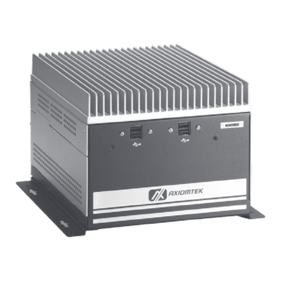
IPC910H Series. Chapter 1 includes the following sections: General Description System Specification Dimensions I/O Outlets Package List General Description The IPC910H Series is an embedded system that can support Socket ® ® M for Intel Core 2 Duo/ Core Duo or Celeron M processors. -
Page 10: System Specifications
IPC910H Series User’s Manual Reliable and Stable Design The IPC910H Series adopts an anti-vibration hard-drive bay, which makes it especially suitable for vibration environments, best for industrial automation, digital signage and gaming application. Embedded O.S. Supported ® The IPC910H Series not only supports Windows 2000, ®... -
Page 11: I/O System
IPC910H Series User’s Manual 1.2.2 I/O System I/O Interface -- Rear ATX power on/off switch One 2-pin connector output for remote power on/off switch 18VDC to 28VDC with phoenix power plug or External 90W AC Adapter One PS/2 keyboard/mouse connector One VGA connector Two USB 2.0 ports... - Page 12 IPC910H Series User’s Manual ™ CompactFlash Socket Power Input 18VDC to 28VDC with phoenix power plug External 90W AC Adapter – Power Input – 90VAC to 264VAC, 6.32A 47/63HZ – Power Output – 19VDC Operation Temperature Ambient with air flow: -5℃ ~ 45℃...
-
Page 13: Dimensions
IPC910H Series User’s Manual Dimensions The following diagrams show you dimensions and outlines of the IPC910H Series. Introduction... -
Page 14: I/O Outlets
IPC910H Series User’s Manual I/O Outlets The following figures show you I/O outlets on front and rear panels of the IPC910H Series. Rear Panel Front Panel Introduction... -
Page 15: Jumper Settings
IPC910H Series User’s Manual Jumper Settings The IPC910H has a number of jumpers inside the chassis that allow you to configure your system to suit your application. The table below lists the functions of the various jumpers. Jumper Description Jumper Setting... - Page 16 IPC910H Series User’s Manual COM1 RS232/422/485 Jumper Setting Jumper Description Jumper Setting Description Jumper Setting COM1 RS-232 (Default) RS-422 RS-485 Backplane Jumper Setting Use this jumper to select PCIe x1 or PCIe x 4 by the following setting. Jumper Description...
-
Page 17: Packing List
IPC910H Series User’s Manual Packing List The package bundled with your IPC910H Series should contain the following items: IPC910H Series Unit x 1 DIN 6P-6P PS/2 KB + MOUSE (RC) x 1 TB HD-515 3P (F) 180D P=5.08 GREEN RC x 1 (for IPC910H-P) - Page 18 IPC910H Series User’s Manual MEMO Introduction...
-
Page 19: Chapter 2 Hardware Installation
IPC910H Series User’s Manual CHAPTER 2 HARDWARE INSTALLATION The IPC910H Series are convenient for your various hardware configurations, such as CPU (Central Processing Unit), Memory Module, HDD (Hard Disk Drive) and PCIe card. The chapter 2 will show you how to install the hardware. It includes: Installing the Processor ®... - Page 20 IPC910H Series User’s Manual If the cooling solution prevents you from accessing the processor socket, you may need to remove it. Instructions on how to remove your cooling solution should be provided in the documentation that came with the system.
- Page 21 IPC910H Series User’s Manual Step 4 After opening the top and side covers, you can locate the CPU socket and heatsink as marked. Step 5 Align pins of the CPU with pin holes of the socket. Be careful of the CPU’s orientation that you need to align the arrow mark on the CPU with the arrow key on the socket.
- Page 22 IPC910H Series User’s Manual Step 6 Place the CPU Heatsink on the CPU, and lock it by pushing down the fixing buttons. Step 7 Close the side and top covers back to the chassis, and fasten all screws. Hardware Installation...
-
Page 23: Installing The Memory Module
IPC910H Series User’s Manual Installing the Memory Module Step 1 Turn off the system. Step 2 Disconnect the power connector. Step 3 Loosen screws to remove the side cover from the chassis. Step 4 Please follow steps below to install the memory module: 1. - Page 24 IPC910H Series User’s Manual 2. Install the memory module into the socket and push it firmly down until it is fully seated. The socket latches are clipped on to the edges of the SO-DIMM. Step 5 Put back the side cover to the chassis and fasten all screws.
-
Page 25: Installing The Hard Disk Drive
IPC910H Series User’s Manual Installing the Hard Disk Drive The IPC910H Series offers a convenient drive bay module for users to install HDD. The system offers users one 2.5” Hard Disk Drive for installation. Please follow the steps: Step 1 Turn off the system. - Page 26 IPC910H Series User’s Manual Step 5 Use assembly parts to fix HDD with the bracket. Step 6 Install and fix the HDD through the bottom, next, plug the power cable in HDD. Step 7 Close the side cover back to the chassis and fasten all screws.
-
Page 27: Installing The Pcie Card (When Backplane Hab100 Installed)
IPC910H Series User’s Manual Installing the PCIe Card (when Backplane HAB100 installed) Notes The system provides two PCIe slots when backplane HAB100 is installed. You can install one PCIe x1 and one PCIe x4; or two PCIe x1. Step 1 Turn off the system. - Page 28 IPC910H Series User’s Manual Step 4 Locate the PCIe slots from the side. Step 5 Align the PCIe card with the slot, and press the card into the slot until it is firmly seated. Hardware Installation...
- Page 29 IPC910H Series User’s Manual Step 6 One PCIe x1 and one PCIe x4 can be installed; or, two PCIe Step 7 Close the side cover back to the chassis and fasten all screws. Hardware Installation...
-
Page 30: Installing The Pcie Card (When Backplane Hab103 Installed)
IPC910H Series User’s Manual Installing the PCIe Card (when Backplane HAB103 installed) Notes The system provides PCI & PCIe slots when backplane HAB103 is installed. You can install one PCI and one PCIe x4. Step 1 Turn off the system. - Page 31 IPC910H Series User’s Manual Step 4 Locate the PCIe slots from the side. Step 5 Align the PCIe card with the slot, and press the card into the slot until it is firmly seated. One PCI and one PCIe x4 can be installed.
- Page 32 IPC910H Series User’s Manual MEMO Hardware Installation...
-
Page 33: Chapter 3 Phoenix-Award Bios Utility
IPC910H Series User’s Manual CHAPTER 3 PHOENIX-AWARD BIOS UTILITY The Phoenix-Award BIOS provides users with a built-in Setup program to modify basic system configuration. All configured parameters are stored in a battery-backed-up RAM (CMOS RAM) to save the Setup information whenever the power is turned off. -
Page 34: Control Keys
IPC910H Series User’s Manual Control Keys Move cursor to the previous item Up arrow Move cursor to the next item Down arrow Move cursor to the item on the left hand Left arrow Move to the item in the right hand... -
Page 35: The Main Menu
IPC910H Series User’s Manual The Main Menu Once you enter the Award BIOS CMOS Setup Utility, the Main Menu appears on the screen. In the Main Menu, there are several Setup functions and a couple of Exit options for your selection. Use arrow keys to select the Setup Page you intend to configure then press <Enter>... -
Page 36: Standard Cmos Setup Menu
IPC910H Series User’s Manual Standard CMOS Setup Menu The Standard CMOS Setup Menu displays basic information about your system. Use arrow keys to highlight each item, and use <PgUp> or <PgDn> key to select the value you want in each item. - Page 37 IPC910H Series User’s Manual IDE Channel 0/1/2/3 Master/IDE Channel 0/1/2/3 Slave These items identify the types of each IDE channel installed in the computer. There are 45 predefined types (Type 1 to Type 45) and 2 user’s definable types (Type User) for Enhanced IDE BIOS. Press <PgUp>/<+>...
- Page 38 IPC910H Series User’s Manual Halt On This item determines whether the system will halt or not, if an error is detected while powering up. The system booting will halt on any errors detected. No errors (default) Whenever BIOS detects a non-fatal error, the All errors system will stop and you will be prompted.
-
Page 39: Advanced Bios Features
IPC910H Series User’s Manual Advanced BIOS Features This section allows you to configure and improve your system, to set up some system features according to your preference. Phoenix-Award BIOS Utility... - Page 40 IPC910H Series User’s Manual CPU Feature Scroll to this item and press <Enter> to view the CPU Feature sub menu. Delay prior to Thermal This filed is used to select the time that would force the CPU to a 50% duty cycle when it exceeds its maximum operating...
- Page 41 IPC910H Series User’s Manual Hard Disk Boot Priority Scroll to this item and press <Enter> to view the sub menu to decide the disk boot priority. Press <Esc> to return to the Advanced BIOS Features page. Phoenix-Award BIOS Utility...
- Page 42 IPC910H Series User’s Manual Virus Warning This option flashes on the screen. During and after the system boot up, any attempt to write to the boot sector or partition table of the hard disk drive will halt the system with the following message. You can run an anti-virus program to locate the problem.
- Page 43 IPC910H Series User’s Manual Boot Other Device This item allows users to enable or disable the boot device not listed in the First/Second/Third boot devices option above. The default setting is “Enabled”. Boot Up Floppy Seek During POST, BIOS will determine the floppy disk drive type, 40 or 80 tracks.
- Page 44 IPC910H Series User’s Manual APIC Mode Use this item to enable or disable APIC (Advanced Programmable Interrupt Controller) mode that provides symmetric multi-processing (SMP) for systems. MPS Version Control For OS This item specifies the version of the Multiprocessor Specification (MPS).
-
Page 45: Advanced Chipset Features
IPC910H Series User’s Manual Advanced Chipset Features This section contains completely optimized chipset’s features on the board that you are strongly recommended to leave all items on this page at their default values unless you are very familiar with the technical specifications of your system hardware. - Page 46 IPC910H Series User’s Manual Express graphics card is detected, the board will boot up using that card. Otherwise, it is defaulted to the onchip graphics processor. On-Chip Frame Buffer Size Use this item to set the VGA frame buffer size.
-
Page 47: Integrated Peripherals
IPC910H Series User’s Manual Integrated Peripherals This section allows you to configure your SuperIO Device, IDE Function and Onboard Device. Phoenix-Award BIOS Utility... - Page 48 IPC910H Series User’s Manual OnChip IDE Device Scroll to this item and press <Enter> to view the sub menu OnChip IDE Device. IDE HDD Block Mode Block mode is also called block transfer, multiple commands, or multiple sectors read/write. If your IDE hard drive...
- Page 49 IPC910H Series User’s Manual automatically remove the IDE Primary Master/ Slave PIO and/or IDE Secondary Master/Slave PIO items on the menu. IDE Primary/Secondary Master/Slave PIO The four IDE PIO (Programmed Input/Output) fields let you set a PIO mode (0-4) for each of the four IDE devices that the onboard IDE interface supports.
- Page 50 IPC910H Series User’s Manual Onboard Device Scroll to this item and press <Enter> to view the sub menu Onboard Device. USB Controller Enable this item if you are using the USB in the system. You should disable this item if a higher-level controller is added.
- Page 51 IPC910H Series User’s Manual Super IO Device Scroll to this item and press <Enter> to view the sub menu Super IO Device. POWER ON Function This item provides several ways to power up the system: BUTTON ONLY, Keyboard 98, Password, Hot Key, Mouse Left, Mouse Right and Any Key.
- Page 52 IPC910H Series User’s Manual Parallel Port Mode Select an operating mode for the onboard parallel (printer) port. Select Normal unless your hardware and software require another mode in this field. Options: EPP1.9, ECP, SPP, ECPEPP1.7, EPP1.7. EPP Mode Select Select EPP port type 1.7 or 1.9.
-
Page 53: Power Management Setup
IPC910H Series User’s Manual Power Management Setup The Power Management Setup allows you to save energy of your system effectively. It will shut down the hard disk and turn OFF video display after a period of inactivity. Phoenix-Award BIOS Utility... - Page 54 IPC910H Series User’s Manual PCI Express PM Function. Scroll to this item and press <Enter> to view the sub menu of PCI Express PM Function. Scroll to this item and press <Enter> to view the sub menu of PCI Express PM Function. PCI Express...
- Page 55 IPC910H Series User’s Manual of this field. Options are: [S1 (POS)] The S1 sleep mode is a low power state. In this state, no system context is lost (CPU or chipset) and hardware maintains all system contexts. [S3 (STR)] The S3 sleep mode is a lower power state where...
- Page 56 IPC910H Series User’s Manual Suspend Type If this item is set to the default Stop Grant, the CPU will go into Idle Mode during power saving mode. Suspend Mode After a selected period of system inactivity (1 minute to 1 hour), all devices except the CPU shut off.
-
Page 57: Pnp/Pci Configuration Setup
IPC910H Series User’s Manual 3.10 PnP/PCI Configuration Setup This section describes the configuration of PCI (Personal Computer Interconnect) bus system, which allows I/O devices to operate at speeds close to the CPU speed while communicating with other important components. This section covers very technical items that only experienced users could change default settings. - Page 58 IPC910H Series User’s Manual disappear, as the BIOS automatically assigns them. The default value is “Manual”. IRQ Resources When resources are controlled manually, assign each system interrupt to one of the following types in accordance with the type of devices using the interrupt: 1.
-
Page 59: Pc Health Status
IPC910H Series User’s Manual 3.11 PC Health Status This section supports hardware monitoring that lets you monitor those parameters for critical voltages, temperatures and fan speed of the board. Current System Temperature Show you the current system temperature. Current CPU Temperature The current system CPU temperature will be automatically detected by the system. -
Page 60: Frequency/Voltage Control
IPC910H Series User’s Manual 3.12 Frequency/Voltage Control This section is to control the CPU frequency and Supply Voltage, DIMM OverVoltage and AGP voltage. Auto Detect PCI Clk The enabled item can automatically disable the clock source for a PCI slot without a module, to reduce EMI (ElectroMagnetic Interference). -
Page 61: Load Optimized Defaults
IPC910H Series User’s Manual 3.13 Load Optimized Defaults This option allows you to load your system configuration with default values. These default settings are optimized to enable high performance features. To load CMOS SRAM with SETUP default values, please enter “Y”. If not, please enter “N”. -
Page 62: Set Supervisor/User Password
IPC910H Series User’s Manual 3.14 Set Supervisor/User Password You can set a supervisor or user password, or both of them. The differences between them are: Supervisor password: You can enter and change the options on the setup menu. User password: You can just enter, but have no right to change the options on the setup menu. -
Page 63: Save & Exit Setup
IPC910H Series User’s Manual 3.15 Save & Exit Setup This section allows you to determine whether or not to accept your modifications. Type “Y” to quit the setup utility and save all changes into the CMOS memory. Type “N” to bring you back to the Setup utility. -
Page 64: Exit Without Saving
IPC910H Series User’s Manual 3.16 Exit Without Saving Select this option to exit the Setup utility without saving changes you have made in this session. Type “Y”, and it will quit the Setup utility without saving your modifications. Type “N” to return to the Setup utility.
Need help?
Do you have a question about the IPC910H Series and is the answer not in the manual?
Questions and answers