Table of Contents
Advertisement
Quick Links
Advertisement
Table of Contents

Related Manuals for AXIOMTEK ICO330


Summary of Contents for AXIOMTEK ICO330
- Page 1 ICO330 Robust Din-rail Fanless Embedded System User’s Manual...
- Page 2 Axiomtek does not make any commitment to update the information in this manual. Axiomtek reserves the right to change or revise this document and/or product at any time without notice.
-
Page 3: Safety Precautions
Safety Precautions Before getting started, please read the following important safety precautions. The ICO330 does not come equipped with an operating system. An operating system must be loaded first before installing any software into the computer. Be sure to ground yourself to prevent static charge when installing the internal components. -
Page 4: Classification
Classification Degree of production against electric shock: not classified Degree of protection against the ingress of water: IP30 Equipment not suitable for use in the presence of a flammable anesthetic mixture with air or with oxygen or nitrous oxide. Mode of operation: Continuous Type of protection against electric shock: Class I equipment General Cleaning Tips You may need the following precautions before you begin to clean the computer . - Page 5 Cleaning Tools Although many companies have created products to help improve the process of cleaning your computer and peripherals users can also use household items to clean their computers and peripherals. Below is a listing of items you may need or want to use while cleaning your computer or computer peripherals.
-
Page 6: Scrap Computer Recycling
For the computers that are no longer useful or no longer working well, please contact your Axiomtek distributor for recycling and we will make the proper arrangement. Trademarks Acknowledgments Axiomtek is a trademark of Axiomtek Co., Ltd. IBM, PC/AT, PS/2, VGA are trademarks of International Business Machines Corporation. ® ®... -
Page 7: Table Of Contents
Table of Contents Safety Precautions ....................iii Classification ......................iv General Cleaning Tips ..................iv Scrap Computer Recycling ................... vi SECTION 1 INTRODUCTION................. 1 General Description ................1 System Specifications ............... 4 1.2.1 CPU ........................4 1.2.2 BIOS ........................4 1.2.3 System Memory .................... - Page 8 This page is intentionally left blank. viii...
-
Page 9: Section 1 Introduction
(1.5GHz) processors supporting industrial temperature range of -40℃ to +70℃. Its front accessible I/O cabling is very convenient for wiring and maintenance. ICO330 offers a HDMI output, making it particularly well-suited for data acquisition, communication control, SCADA and industrial automation. - Page 10 ICO330 Series User’s Manual ⚫ Checklist (Full Mode) ✓ ✓ ICO330 System Unit x 1 Din-rail Kit x1Set ✓ ✓ DDR thermal pad x1 DIO 2x6pin termninal block x2 ✓ ✓ M.2 Key B thermal pad x1 COM 2x5pin termninal block x6 ✓...
- Page 11 Embedded O.S. Supported ® ◼ ICO330 not only supports Windows 10/11, but also supports embedded OS, such ® as Windows 10/11 IoT and Linux package support. For storage device, ICO330 supports one SATA SSD, one mSATA, one 8GB eMMC. Introduction...
-
Page 12: System Specifications
ICO330 Series User’s Manual System Specifications 1.2.1 ⚫ Onboard Intel® Atom® x6212RE (1.2GHz) or x6414RE (1.5GHz) 1.2.2 BIOS ⚫ AMI (American Megatrends Inc.) UEFI (Unified Extensible Firmware Interface) BIOS. 1.2.3 System Memory ⚫ One DDR4-3200 260-pin SO-DIMM slot. ⚫ Supports 3200 MHz up to 32GB. -
Page 13: System Block Diagram
ICO330 Series User’s Manual 1.2.5 System Block diagram Introduction... -
Page 14: Ethernet Ports
ICO330 Series User’s Manual 1.2.6 Ethernet Ports ⚫ LAN Chip: Intel Ethernet Controller I226-IT. ⚫ LAN1~3 support 100/1000/2500 Base-T with 1.5KV magnetic isolated protection. 1.2.7 Storages ⚫ 1 x 2.5” SATA drive bay. ⚫ 1 x mSATA. ⚫ 1 x 8GB eMMC 1.2.8... - Page 15 ICO330 Series User’s Manual PSB521 Buttom View AX93670 TOP View AX93670 Buttom View Introduction...
-
Page 16: Connectors
ICO330 Series User’s Manual Connectors 1.2.10 Signals go to other parts of the system through connectors. Loose or improper connection might cause problems, please make sure all connectors are properly and firmly connected. Here is a summary table which shows all connectors on the hardware. -
Page 17: Com
ICO330 Series User’s Manual 1.2.11 ⚫ 6 ports terminal block support RS-232/422/485 which can be selected by BIOS with isolation 2KV protection. ⚫ Supports Auto Flow Control in RS485 mode. ⚫ Serial Port Pin Define: COM1~2 RS232 RS422 RS485 COM3~6... -
Page 18: Digital I/O Connector And Pin Definition
ICO330 Series User’s Manual 1.2.12 Digital I/O Connector and Pin Definition ⚫ 8bit DI and 8bit DO with 2KV optical isolation (only for fully type) Digital Input Input Channels 8 source type Input Voltage 0 to 30VDC Input Digital Input Levels for Logic level 0: Close to GND. - Page 19 ICO330 Series User’s Manual 12 COM- ⚫ When the external device inputs a high-level pulse, DI will correspond to logic low- level. If the controller reads the same logic as the external state, it needs to be inverted in software to get the high state.
-
Page 20: Power
ICO330 Series User’s Manual 1.2.13 Power ⚫ Wide-range 12 - 24V DC power input with terminal block. Signal VIN + VIN - 1.2.14 WatchDog Timer (WDT) ⚫ 1~255 seconds or minutes; up to 255 levels 1.2.15 Restore BIOS Optimal Defaults (Clear CMOS) ⚫... -
Page 21: Operation Temperature
ICO330 Series User’s Manual 1.2.17 Operation Temperature ⚫ C ~ +70 1.2.18 Storage Temperature ⚫ C ~ +85 1.2.19 Humidity ⚫ 10% ~ 95% (non-condensation) 1.2.20 Weight ⚫ Slim Mode: 0.9 kg ⚫ Full Mode: 1.1 kg 1.2.21 Dimensions (W x D x H) ⚫... -
Page 22: Dimensions
ICO330 Series User’s Manual Dimensions The following diagrams show you dimensions and outlines of the ICO330. Full Mode Introduction... - Page 23 ICO330 Series User’s Manual Slim Mode Introduction...
-
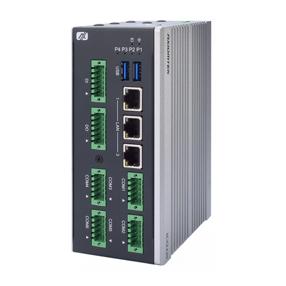
Page 24: I/O Outlets
ICO330 Series User’s Manual I/O Outlets The following figures show you I/O outlets on front view and top view of the ICO330. Introduction... -
Page 25: Section 2 Hardware Installation
ICO330 Series User’s Manual SECTION 2 HARDWARE INSTALLATION The ICO330 is convenient for your various hardware configurations, such as Memory Module and Hard Disk Drive. The chapter 2 will show you how to install the hardware. It includes: Installing the Memory Module Step 1 Turn off the system. - Page 26 ICO330 Series User’s Manual Step 3 Put the thermal pad on the memory module to improve cooling effect. Step 4 Use two fingers to hold the memory module and insert the gold figure into the slot and push the module down.
- Page 27 ICO330 Series User’s Manual Step 6 Stick thermal pad onto DDR Step 7 Install DDR bracket Step 8 The bracket screws it tight. Slim Mode Hardware Installation...
- Page 28 ICO330 Series User’s Manual Step 9 Put the cover back to the system and fasten screws tight close the chassis. Hardware Installation...
-
Page 29: Installing The Msata Pcie Usb Module
ICO330 Series User’s Manual Installing the mSATA PCIe USB module Step 1 Turn off the system. Step 2 Loosen all screws of the cover and remove the cover from the system. Slim Mode Full Mode - step1 Hardware Installation... - Page 30 ICO330 Series User’s Manual Full Mode - Step2 Full Mode - Step3 Full Mode - Step4 Hardware Installation...
- Page 31 ICO330 Series User’s Manual Full Mode - Step5 Full Mode - Step6 Step 3 Insert the mSATA into the slot which marking with “mSATA / USB / PCIe ” and fasten screws. Step 4 Put the cover back to the system and fasten screws tight close the chassis.
-
Page 32: Installing Wireless Module(3G/Lte)
ICO330 Series User’s Manual Installing Wireless Module(3G/LTE) Step 1 Turn off the system. Step 2 Loosen all screws of the cover and remove the cover from the system. Slim Mode Full Mode - step1 Hardware Installation... - Page 33 ICO330 Series User’s Manual Full Mode - Step2 Full Mode - Step3 Full Mode - Step4 Hardware Installation...
- Page 34 ICO330 Series User’s Manual Full Mode - Step5 Full Mode - Step6 Step 3 Following(Figure 3-1) push the SIM slot back to unlock SIM slot, inserting the SIM card and put it back(Figure 3-2), and lock the SIM slot(Figure 3-3).
- Page 35 ICO330 Series User’s Manual Figure 3-3 Step4. Insert the wireless module into the slot which marking with “USB ”. Hardware Installation...
- Page 36 ICO330 Series User’s Manual Step 5 Insert the 4G/LTE module and screws it tight. Step 6 Removing the plug cover from the chassis. Slim Mode Full Mode Hardware Installation...
- Page 37 ICO330 Series User’s Manual Connect the RF cable to the connector of 4G/LTE module which “MAIN”. Step 7 Step 8 Taking out the parts from the 4G/LTE kit package (Figure 8-1) and make the RF cable through the antenna hole (Figure 8-2). Finally, screw it tight(Figure 8-...
- Page 38 ICO330 Series User’s Manual Figure 8-2 Figure 8-3 Step 9 Screwing the RF antenna tight. Step 10 Put the cover back to the system and fasten screws tight close the chassis. Hardware Installation...
-
Page 39: Installing Wireless Module(5G/Lte)
ICO330 Series User’s Manual Installing Wireless Module(5G/LTE) Step 1 Turn off the system. Step 2 Loosen all screws of the cover and remove the cover from the system. Slim Mode Full Mode - Step1 Hardware Installation... - Page 40 ICO330 Series User’s Manual Full Mode - Step2 Full Mode - Step3 Full Mode - Step4 Hardware Installation...
- Page 41 ICO330 Series User’s Manual Full Mode - Step5 Full Mode - Step6 Hardware Installation...
- Page 42 ICO330 Series User’s Manual Step 3 Following(Figure 3-1) push the SIM slot back to unlock SIM slot, inserting the SIM card and put it back(Figure 3-2), and lock the SIM slot(Figure 3-3). Figure 3-1 Figure 3-2 Figure 3-3 Hardware Installation...
- Page 43 ICO330 Series User’s Manual Step4. Insert the wireless module into the slot which marking with “USB ”. Hardware Installation...
- Page 44 ICO330 Series User’s Manual Step 5 Insert the 5G/LTE module and screws it tight. Step 6 Removing the plug cover from the chassis. Slim Mode Full Mode Hardware Installation...
- Page 45 ICO330 Series User’s Manual Connect the RF cable to the connector of 5G/LTE module which “MAIN”. Step 7 Step 8 Stick thermal pad onto 5G/LTE Hardware Installation...
- Page 46 ICO330 Series User’s Manual Step 9 Install 5G/LTE bracket Step 10 The bracket screws it tight. Slim Mode Full Mode Hardware Installation...
- Page 47 ICO330 Series User’s Manual Step 11 Taking out the parts from the 4G/LTE kit package (Figure 8-1) and make the RF cable through the antenna hole (Figure 8-2). Finally, screw it tight(Figure 8- Figure Figure 8-2 Figure 8-3 Step 12 Screwing the RF antenna tight.
- Page 48 ICO330 Series User’s Manual Note: SIM Card only can use the standard size as the following pictures. Hardware Installation...
-
Page 49: Installing The Hard Disk Drive
ICO330 Series User’s Manual Installing the Hard Disk Drive Step 1 Turn off the system. Step 2 Loosen all screws of the cover and remove the cover from the system. Slim Mode Full Mode Hardware Installation... - Page 50 ICO330 Series User’s Manual Step 3 Loosen 4pcs screws of the cover, and put the SSD into the SSD bracket and fix the SSD by 4pcs of screws in the accessory bag. Slim Type Full Type Step 4 Put the SSD bracket on the cover and use 4pcs screws to fix tightly. Taes the...
- Page 51 ICO330 Series User’s Manual Step 5 Connect SATA+Power SSD cable to the board connector, SATA side first then power side second. Slim Type Full Type Step 6 Put the cover back to the system and fasten screws tight close the chassis.
-
Page 52: Installing Din-Rail Mounting (Screw: M3 X 6 4Pcs)
ICO330 Series User’s Manual Installing Din-rail Mounting (Screw: M3 x 6 4pcs) The ICO330 provides Din-rail Mount for 2 methods that customers can install as below: Step 1 Prepare Din-rail Mount assembling components (screws and bracket) ready. Step 2 Assembly the bracket to the system and fasten screws tight. -
Page 53: Section 3 Ami Uefi Bios Utility
ICO330 Series User’s Manual SECTION 3 AMI UEFI BIOS UTILITY The AMI UEFI BIOS provides users with a built-in Setup program to modify basic system configuration. All configured parameters are stored in a flash-backed-up to save the Setup information whenever the power is turned off... -
Page 54: Advanced Features
ICO330 Series User’s Manual Advanced Features This Advanced section allows users to configure and improve your system, to set up some system features according to your preference. You can select any of the items in the left frame of the screen to go to the sub menus:... - Page 55 ICO330 Series User’s Manual ⚫ CPU Configuration Scroll to this item and press <Enter> to view the CPU Configuration informations. (Please refer below graphics.) AMI UEFI BIOS Utility...
- Page 56 ICO330 Series User’s Manual ⚫ USB Configuration Scroll to this item and press <Enter> to view the SATA Configuration informations. (Please refer below graphics.) AMI UEFI BIOS Utility...
- Page 57 ICO330 Series User’s Manual ⚫ Hardware Monitor Scroll to this item and press <Enter> to view the monitor hardware status. (Please refer below graphics.) AMI UEFI BIOS Utility...
- Page 58 ICO330 Series User’s Manual ⚫ F81804 Super IO Configuration The default setting for all Serial Ports are RS232. You can change the setting by selecting the value you want in each COM Port Type. Supports RS422 & RS485 mode. (Please refer below graphics.)
- Page 59 ICO330 Series User’s Manual You can enable COM port RS-422/485 receiver termination in RS422/485 mode. AMI UEFI BIOS Utility...
- Page 60 ICO330 Series User’s Manual You can enable COM port High-speed mode to support higher speed com port buard rate in RS422/485 mode. Disable Enable 1430 134.5 1478.5 1950 3900 7800 1200 15600 1800 23400 2000 26000 2400 31200 3600 46800...
- Page 61 ICO330 Series User’s Manual ⚫ Storage Configuration Scroll to this item and press <Enter> to view the Storage Configuration information. (Please refer below graphics.) AMI UEFI BIOS Utility...
- Page 62 ICO330 Series User’s Manual ⚫ PCIe/mSATA Mini Card Configuration Scroll to this item and press <Enter> to view the SATA Configuration information and choose PCIE Mini Card as PCIE or mSATA. (Please refer below graphics.) AMI UEFI BIOS Utility...
- Page 63 ICO330 Series User’s Manual ⚫ eMMC Device Information Scroll to this item and press <Enter> to view the EMMC Device information. (Please refer below graphics.) AMI UEFI BIOS Utility...
- Page 64 ICO330 Series User’s Manual ⚫ Serial Port Console Redirection Only COM1 has the console redirection function. The default setting for the console redirection function is [Disabled] (Please refer below graphics.) AMI UEFI BIOS Utility...
- Page 65 ICO330 Series User’s Manual And you can further change the setting by selecting or setting the value you want in each function as the following pictures. AMI UEFI BIOS Utility...
- Page 66 ICO330 Series User’s Manual ⚫ Trusted Computing Scroll to this item and press <Enter> to view the Trusted Computing information and default set Security Device Support [Enable]. (Please refer below graphics.) AMI UEFI BIOS Utility...
-
Page 67: Chipset Feature
ICO330 Series User’s Manual Chipset Feature AMI UEFI BIOS Utility... - Page 68 ICO330 Series User’s Manual AMI UEFI BIOS Utility...
-
Page 69: Security
ICO330 Series User’s Manual Security The default setting for Administrator Password is “Not setting passwords”. The Security menu allows users to change the security settings for the system. You can set the password for Administrator Password. (Please refer below graphics.) Note: The BIOS default has no password, when user created the password, please remember the password number, if users forget password the RMA is the only solution. -
Page 70: Boot Type
ICO330 Series User’s Manual Boot Type The default setting boot from onboard Launch PxE is [Disabled] (Please refer below graphics.) AMI UEFI BIOS Utility... - Page 71 ICO330 Series User’s Manual The setting boot from PinCntrl Driver GPIO Scheme is the item can let user choose which operating system want to boot. (Please refer below graphics.) The Boot Option Priorities can select by Boot Option #1, #2…, If user is using a USB Device.
- Page 72 ICO330 Series User’s Manual AMI UEFI BIOS Utility...
-
Page 73: Save & Exit
ICO330 Series User’s Manual Save & Exit This section allows you to determine whether or not to accept your modifications. (Please refer below graphics.) AMI UEFI BIOS Utility... - Page 74 ICO330 Series User’s Manual This page is intentionally left blank. AMI UEFI BIOS Utility...
-
Page 75: Appendix Awatchdog Timer
ICO330 Series User’s Manual APPENDIX A WATCHDOG TIMER About Watchdog Timer After the system stops working for a while, it can be auto-reset by the watchdog timer. The integrated watchdog timer can be set up in the system reset mode by program. - Page 76 ICO330 Series User’s Manual int main() unsigned char Count = 10; // 10 Seconds unsigned char DataBuffer; // Operate Io Data //Get Io Port Read/Write Permission iopl(3); //Enter SIO Config outb_p ( SIO_ENTRY_KEY, SIO_INDEX); outb_p ( SIO_ENTRY_KEY, SIO_INDEX); // Set WDT IOBASE // Select Logical Device = 07 (WDT) outb_p ( SIO_REG_LDN , SIO_INDEX);...
- Page 77 ICO330 Series User’s Manual Wdt Config Reg Bit Definition 7 : Reserved 6 : WDT time out Status (Write 1 Clear) 5 : Watch dog counting Enable 4 : Set Output mode (0 Level,1 Edge) 3 : Time Unit (0 : 1sec , 1: 60Sec)
Need help?
Do you have a question about the ICO330 and is the answer not in the manual?
Questions and answers