Table of Contents
Advertisement
Quick Links
Advertisement
Table of Contents

Related Manuals for AXIOMTEK IPC932-230-FL Series


Summary of Contents for AXIOMTEK IPC932-230-FL Series
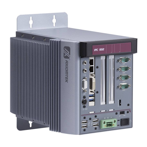
- Page 1 IPC932-230-FL Series Industrial and Fanless Computers User’s Manual...
- Page 2 Axiomtek does not make any commitment to update the information in this manual. Axiomtek reserves the right to change or revise this document and/or product at any time without notice.
-
Page 3: Safety Precautions
Safety Precautions Before getting started, please read the following important safety precautions. The IPC932-230-FL Series does not come equipped with an operating system. An operating system must be loaded first before installing any software into the computer. Be sure to ground yourself to prevent static charge when installing the internal components. -
Page 4: Classification
Classification Degree of production against electric shock: not classified Degree of protection against the ingress of water: IPX0 Equipment not suitable for use in the presence of a flammable anesthetic mixture with air or with oxygen or nitrous oxide. Mode of operation: Continuous Type of protection against electric shock: Class I equipment General Cleaning Tips You may need the following precautions before you begin to clean the computer . - Page 5 Cleaning Tools: Although many companies have created products to help improve the process of cleaning your computer and peripherals users can also use household items to clean their computers and peripherals. Below is a listing of items you may need or want to use while cleaning your computer or computer peripherals.
-
Page 6: Scrap Computer Recycling
If the computer equipments need the maintenance or are beyond repair, we strongly recommended that you should inform your Axiomtek distributor as soon as possible for the suitable solution. For the computers that are no longer useful or no longer working well, please contact your Axiomtek distributor for recycling and we will make the proper arrangement. -
Page 7: Table Of Contents
Table of Contents Safety Precautions ....................iii Classification ......................iv General Cleaning Tips ..................iv Scrap Computer Recycling .................. vi CHAPTER 1 INTRODUCTION ................1 General Description ................1 System Specifications ..............2 1.2.1 Main CPU Board ....................2 1.2.2 I/O System ...................... - Page 8 Security Menu .................. 43 Save & Exit Menu ................44 viii...
-
Page 9: Chapter 1 Introduction
W indows 8 and W indows 7 embedded, and Fedora, suitable for the most endurable operation. The IPC932-230-FL Series support two hard-drive bays, which makes it easy to install for customer maintain the system. Embedded O.S. Supported ®... -
Page 10: System Specifications
IPC932-230-FL User’s Manual System Specifications 1.2.1 Main CPU Board ® Socket LGA1150 for 4 Generation Intel Core i7/i5/i3 processors, up to 45W System Chipset ® Intel Q87 chipset BIOS AMI BIOS, with Smart View and Customer CMOS Backup. ... -
Page 11: 1.2.3 System Specification
IPC932-230-FL User’s Manual Expansion Slot HAB100: PCIe x1 & 1 PCIe x4 HAB103: 1 PCIe x4 & 1 PCI ℃ Note: The maximum power rating for expansion slots at 50 can not be exceeded the following values The maximum loading of +3.3V /1A, +5V /5A ,+12V /3A<60W 1.2.3 System Specification ... -
Page 12: Dimensions
IPC932-230-FL User’s Manual Dimensions The following diagrams show you dimensions and outlines of the IPC932-230-FL Series. Introduction... -
Page 13: I/O Outlets
IPC932-230-FL User’s Manual I/O Outlets The following figures show you I/O outlets on front and rear panels of the IPC932- 230-FL Series. Front Panel Audio(Mic-in/Line out) Digital I/O PS/2 Keyboard/Mouse USB 2.0 x 4 Ethernet x 2 DVI-I USB 3.0 x 2 Power connector (Din-Jack or Phoenix plug) LED for Power and HDD 10. -
Page 14: Packing List
HDD Bracket x 2 HDD Mylar x 2 Terminal block x 1 (for DC version) Remote switch cable x 1 If you can not find this package or any items are missing, please contact Axiomtek distributors immediately. Introduction... -
Page 15: Jumper Settings
IPC932-230-FL User’s Manual Jumper Settings The IPC932-230-FL has a number of jumpers inside the chassis that allow you to configure your system to suit your application. The table below lists the functions of the various jumpers. Jumper Description Jumper Setting Audio Amplifier Selection : Disable 1-3 , 2-4 close Clear RTC : Normal... -
Page 16: Connectors
Connector Label External Temperature Sensor Connector (Optional) Digital I/O DVI-I Connector USB Port 3/4 CN10 USB Port 5/6 CN12 Axiomtek Front Panel USB2.0/3.0 Port 1 CN11 PS2 Connector(Keyboard & Mouse) USB2.0/3.0 Port 2 SYS FAN FAN1 FAN2 CPU FAN LAN1... -
Page 17: Digital I/O Connector (Cn1)
IPC932-230-FL User’s Manual 1.7.1 Digital I/O Connector (CN1) The board is equipped with an 8-channel digital I/O connector that meets requirements for a system customary automation control. The digital I/O can be configured to control cash drawers and sense warning signals from an Uninterrupted Power System (UPS), or perform store security control. -
Page 18: Front Panel Connector (Cn3)
IPC932-230-FL User’s Manual 1.7.4 Front Panel Connector (CN3) Signal PW RLED+ EXT SPK- Buzzer PW RLED- N.C. N.C. EXT SPK+ PW RSW - PW RSW + HW RST- HW RST+ HDDLED- HDDLED+ Power LED This 3-pin connector denoted as Pin 1 and Pin 5 connects the system power LED indicator to such a switch on the case. -
Page 19: External Usb 3.0 Connectors (Cn11 And Cn9)
IPC932-230-FL User’s Manual 1.7.5 External USB 3.0 Connectors (CN11 and CN9) These are standard USB 3.0 connectors on rear I/O for installing USB 3.0 compliant interface peripherals. Signal CN11 (USB 3.0 port 1) CN9 (USB 3.0 port 2) StdA_SSRX- StdA_SSRX+ GND_DRAIN StdA_SSTX- StdA_SSTX+... -
Page 20: Fan Connectors (Fan1, Fan2)
IPC932-230-FL User’s Manual 1.7.7 FAN Connectors (FAN1, FAN2) Fans are always needed for cooling down CPU and system temperature. The board has two fan connectors. You can find fan speed option(s) at BIOS Setup Utility if either fan is installed. For further information, see BIOS Setup Utility: Advanced\HW Monitor\PC Health Status.System and auxiliary fan interfaces are available through FAN1 and FAN2, see table below. -
Page 21: Serial Ata Connectors (Sata1~Sata2)
IPC932-230-FL User’s Manual 1.7.9 Serial ATA Connectors (SATA1~SATA2) These Serial Advanced Technology Attachment (Serial ATA or SATA) connectors are for high-speed SATA interfaces. They are computer bus interfaces for connecting to devices such as hard disk drives.This system has two SATA 3.0 ports with 6Gb/s performance. Note: Due to Gen. -
Page 22: Cfast™ Socket (Scf1)
IPC932-230-FL User’s Manual 1.7.10 CFast™ Socket (SCF1) The board is equipped with a CFast socket to support CFast card which is based on the Serial ATA bus. The socket is specially designed to avoid incorrect installation of CFast card. When installing or removing CFast card, please make sure system power is off. -
Page 23: Com Connectors (Com1~Com4)
IPC932-230-FL User’s Manual 1.7.11 COM Connectors (COM1~COM4) The COM1/2 ports supports RS-232/RS-422/RS-485 mode operation, the COM3/4 ports supports RS-232 mode operation, see table below for its pin assignments . You can change the transmission mode via BIOS setting. RS-232 RS-422 RS-485 Data Carrier Detect TX1-... - Page 24 IPC932-230-FL User’s Manual This page is intentionally left blank. Introduction...
-
Page 25: Chapter 2 Hardware Installation
CHAPTER 2 HARDWARE INSTALLATION The IPC932-230-FL Series are convenient for your various hardware configurations, such as CPU (Central Processing Unit), Memory Module, HDD (Hard Disk Drive) and PCIe card. The chapter 2 will show you how to install the hardware. It includes: Installing the Processor The Intel®... - Page 26 IPC932-230-FL User’s Manual Procedure of Installation: Step 1 Turn off the system. Step 2 Disconnect the power connector. Step 3 Loosen screws to remove the Heatsink cover from the chassis. Step 4 After opening the HS cover, you can locate the CPU socket as marked. Align pins of the CPU with pin holes of the socket.
-
Page 27: Installing The Memory Module
IPC932-230-FL User’s Manual Installing the Memory Module Step 1 Turn off the system. Step 2 Disconnect the power connector. Step 3 Loosen screws to remove the Heatsink cover from the chassis. Step 4 Install the memory module into the socket and push it firmly down until it is fully seated. -
Page 28: Installing The Hard Disk Drive
IPC932-230-FL User’s Manual Installing the Hard Disk Drive The IPC932-230-FL Series offers a convenient drive bay module for users to install HDD. The system offers users two 2.5” Hard Disk Drive for installation. Please follow the steps: Step 1 Turn off the system. -
Page 29: Installing The Pci Or Pcie Card
IPC932-230-FL User’s Manual Installing the PCI or PCIe Card IPC932-230-FL provides one PCIex1 and one PCIex4 or one PCI & one PCIex4 for expansion. The procedure of installing the PCI / PCIe expansion card into IPC932-230-FL is instructed below. Step 1 Turn off the system. -
Page 30: Installing The Optinal Fan Module
IPC932-230-FL User’s Manual Installing the optinal Fan Module IPC932-230-FL provides one PCIex1 and one PCIex4 or 1 PCI & 1 PCIex4 for expansion. For the system dissipation generated by PCI/PCIe cards, we strongly suggest that customer should use our optional fan module, to install the optional system fan, please follow the steps below: Step 1 Turn off the system. -
Page 31: Chapter 3 Ami Bios Utility
IPC932-230-FL User’s Manual CHAPTER 3 AMI BIOS UTILITY The AMI UEFI BIOS provides users with a built-in setup program to modify basic system configuration. All configured parameters are stored in a 16MB flash chip to save the setup information whenever the power is turned off. This chapter provides users with detailed description about how to set up basic system configuration through the AMI BIOS setup utility. -
Page 32: Navigation Keys
IPC932-230-FL User’s Manual Navigation Keys The BIOS setup/utility uses a key-based navigation system called hot keys. Most of the BIOS setup utility hot keys can be used at any time during the setup navigation process. These keys include <F1>, <F2>, <Enter>, <ESC>, <Arrow> keys, and so on. Note: Some of the navigation keys differ from one screen to another. -
Page 33: Main Menu
IPC932-230-FL User’s Manual Main Menu The first time you enter the setup utility, you will be in the Main setup screen. You can always return to the Main setup screen by selecting the Main tab. System Time/Date can be set up as described below. The Main BIOS setup screen is shown below. -
Page 34: Advanced Menu
IPC932-230-FL User’s Manual Advanced Menu Launch PXE OpROM Use this item to enable or disable the boot ROM function of the onboard LAN chip when the system boots up. The Advanced menu also allows users to set configuration of the CPU and other system devices. - Page 35 IPC932-230-FL User’s Manual ACPI Settings ACPI configuration can be configured in ACPI Settings. A description of the selected item appears on the right side of the screen. ACPI Sleep State Select the highest ACPI sleep state the system will enter when the suspend button is pressed.
- Page 36 IPC932-230-FL User’s Manual CPU Configuration This screen shows the CPU Configuration, and you can change the value of the selected option. Hyper-threading Use this item to enable or disable Hyper-Threading Technology, which makes a single physical processor perform multi-tasking function as two logical ones. ...
- Page 37 IPC932-230-FL User’s Manual SATA Configuration You can read the current installed hardware configurations from those SATA ports in the SATA Configuration menu. During system boot up, BIOS will detect the present SATA devices automatically. AMI BIOS Utility...
- Page 38 IPC932-230-FL User’s Manual FCH-FW Configuation Display ME firmware information AMI BIOS Utility...
- Page 39 IPC932-230-FL User’s Manual AMT Configuration Enable/Disable Intel Active Management Technology. Configuration options: [Disabled] [Enabled] AMI BIOS Utility...
- Page 40 IPC932-230-FL User’s Manual USB Configuration USB configuration can be configured here by selecting and changing each item. A description of the selected item appears on the right side of the screen. USB Devices Display all detected USB devices. AMI BIOS Utility...
- Page 41 IPC932-230-FL User’s Manual F81801 Super IO Configuration Serial Port 1~2 Configuration Use this item to set parameters of serial port 1 to 2. AMI BIOS Utility...
- Page 42 IPC932-230-FL User’s Manual Serial Port 1 Configuration Serial Port Enable or disable serial port 1. The optimal setting for base I/O address is 3F8h and for interrupt request address is IRQ4. Mode Setting Use this option to set RS-232/RS-422/RS-485 mode for serial port 1. AMI BIOS Utility...
- Page 43 IPC932-230-FL User’s Manual Serial Port 2 Configuration Serial Port Enable or disable serial port 2. The optimal setting for base I/O address is 2F8h and for interrupt request address is IRQ3. Mode Setting Use this option to set RS-232/RS-422/RS-485 mode for serial port 2. AMI BIOS Utility...
- Page 44 IPC932-230-FL User’s Manual F81801 HW Monitor This screen monitors hardware health. Smart Fan Function Enable or disable Smart Fan function. AMI BIOS Utility...
- Page 45 IPC932-230-FL User’s Manual Intel RC Drivers version Detail Displays Version String for drivers AMI BIOS Utility...
-
Page 46: Chipset Menu
IPC932-230-FL User’s Manual Chipset Menu The Chipset menu allows users to change the advanced chipset settings. You can select any of the items in the left frame of the screen to go to the sub menus: ► PCH-IO Configuration ► System Agent (SA) Configuration For items marked with “”, please press <Enter>... - Page 47 IPC932-230-FL User’s Manual PCH-IO Configuration This screen allows you to set PCH parameters. PCH Azalia Configuration Use this item for PCH Azalia configuration settings. AMI BIOS Utility...
- Page 48 IPC932-230-FL User’s Manual System Agent (SA) Configuration This screen shows System Agent information and provides function for specifying related parameters. For items marked with “”, please press <Enter> for more options. Graphics Configuration Use this item for graphics configuration settings. ...
- Page 49 IPC932-230-FL User’s Manual Graphic Configuration Primary Display Allow you to select which graphics controller to use as the primary boot device. Internal Graphic[Auto] Keep IGD enable based on the setup option. Configuration options: [Auto] [Disabled] [Enabled]. Aperture Size [256MB] Set Aperture Size.
-
Page 50: Boot Menu
IPC932-230-FL User’s Manual Boot Menu The Boot menu allows users to change boot options of the system. Setup Prompt Timeout Number of seconds to wait for setup activation key.65535 (0xFFFF) means indefinite waiting. Boot up Unlock State Use this item to select the power-on state for the Unlock. ... - Page 51 IPC932-230-FL User’s Manual Security Menu The Security menu allows users to change the security settings for the system. Administrator Password This item indicates whether an administrator password has been set (installed or uninstalled). User Password This item indicates whether an user password has been set (installed or uninstalled).
- Page 52 IPC932-230-FL User’s Manual Save & Exit Menu The Save & Exit menu allows users to load your system configuration with optimal or fail-safe default values. Save Changes and Exit W hen finish the system configuration settings , select this option to leave Setup and return to Main Menu.
- Page 53 IPC932-230-FL User’s Manual Discard Changes and Reset Select this option to quit Setup without making any permanent changes to the system configuration and reboot the computer. Select Discard Changes and Reset from the Save & Exit menu and press <Enter>. Select Yes to discard changes and reset.
- Page 54 IPC932-230-FL User’s Manual This page is intentionally left blank. AMI BIOS Utility...
Need help?
Do you have a question about the IPC932-230-FL Series and is the answer not in the manual?
Questions and answers