Table of Contents
Advertisement
Quick Links
Advertisement
Table of Contents

Related Manuals for AXIOMTEK IPC972


Summary of Contents for AXIOMTEK IPC972
- Page 1 IPC972 Industrial Computer User’s Manual...
- Page 2 Axiomtek does not make any commitment to update the information in this manual. Axiomtek reserves the right to change or revise this document and/or product at any time without notice.
-
Page 3: Safety Precautions
Safety Precautions Before getting started, please read the following important safety precautions. The IPC972 does not come equipped with an operating system. An operating system must be loaded first before installing any software into the computer. Be sure to ground yourself to prevent static charge when installing the internal components. -
Page 4: Classification
Classification 1. Degree of production against electric shock: not classified 2. Degree of protection against the ingress of water: IPX40 Equipment not suitable for use in the presence of a flammable anesthetic mixture with air or with oxygen or nitrous oxide. 4. - Page 5 Cleaning Tools: Although many companies have created products to help improve the process of cleaning computers and peripherals, users can also use household items to clean their computers and peripherals. Below is a listing of items available for cleaning computers or computer peripherals. Keep in mind that some components in your computer may only be cleaned using a product designed for cleaning components of the same types.
-
Page 6: Scrap Computer Recycling
Scrap Computer Recycling Please inform the nearest Axiomtek distributor as soon as possible for suitable solutions in case computers require maintenance or repair; or for recycling in case computers are out of order or are no longer in use. Trademark Acknowledgments Axiomtek is a trademark of Axiomtek Co., Ltd. -
Page 7: Table Of Contents
Table of Contents Safety Precautions ....................iii Classification ......................iv General Cleaning Tips ..................iv Scrap Computer Recycling ................... vi SECTION 1 INTRODUCTION................. 1 General Description ................1 System Specifications ............... 2 1.2.1 Main CPU Board ....................2 1.2.2 System I/O ......................3 Block Diagrams and Dimensions ............ - Page 8 SECTION 3 AMI BIOS UTILITY ..............53 Starting ..................... 53 Navigation Keys ................54 Main Menu ..................55 Advanced Menu ................56 Chipset Menu ................... 69 Security Menu .................. 78 Boot Menu ..................79 Save & Exit Menu ................80 Appendix A Watchdog Timer ..............
-
Page 9: Section 1 Introduction
10 and Linux, with a rugged design that makes it suitable for the most endurable operation. ➢ The IPC972 provides three hard-drive bays and one M.2 Key M 2280 socket for customers to easily add storage and maintain the system. -
Page 10: System Specifications
IPC972 Series User’s Manual System Specifications 1.2.1 Main CPU Board ⚫ ® Socket LGA1200 for 10 Generation Intel Core i7/i5/i3 and Xeon processors, up to 80W. CPU support is listed as below. Turbo Generation Proc No WATT Core Thread Base frequency... -
Page 11: 1.2.2 System I/O
IPC972 Series User’s Manual ⚫ Features ◼ Front IO design ◼ Supports four expansion slots ◼ DC to DC power supply; supports 24VDC (uMin=19V/uMax=30V) ◼ TPM2.0 ◼ Supports system power on delay function ® ◼ Supports Intel RAID 0,1,5 ◼... - Page 12 One M.2 Key M 2280 socket (PCIe x4 Gen.3) for NVMe SSD Note: Since Gen. 2 SSD with JMicron controller has compatibility issue s with Intel PCH, it is strongly recommended to use Gen. 3 SSD on IPC972. ⚫ Expansion Slot ◼...
- Page 13 IPC972 Series User’s Manual ⚫ Power Input 24VDC (uMin=19V/uMax=30V) with 4-pin phoenix power plug ⚫ Operation Temperature Operating temperature (Ambient with air Proc No WATT core thread base frequency flow & W.T. HDD or W.T. SSD) -10℃-60℃ XeonW-1270TE 2.0 GHz -10℃-60℃...
- Page 14 IPC972 Series User’s Manual ⚫ Humidity 10% ~ 90% (Non-condensing) ⚫ Dimensions 255 mm (W) x 192 mm (H) x 360 mm (D) Note: All specifications and images are subject to change without notice. Introduction...
-
Page 15: Block Diagrams And Dimensions
IPC972 Series User’s Manual Block Diagrams and Dimensions The following figure shows you the system block diagrams of the IPC972. The following diagrams show you the system dimensions. IPC972 system Introduction... - Page 16 IPC972 Series User’s Manual IPC972 system w/ optional 5G antenna bracket Introduction...
-
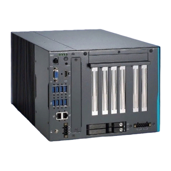
Page 17: Outlets
IPC972 Series User’s Manual Outlets The following figures show you the outlets of the IPC972. Description 1 x SSD/HDD access LED & 3 x user’s LED 1 x Power on/off button w/LED 1 x Line-out 1 x Remote switch & reset switch 1 x VGA &... - Page 18 IPC972 Series User’s Manual 6 x USB3.2 Gen.2 + 2 x USB3.2 Gen.1 (yellow) 1 x i219-LM, 1 x i225-LM (yellow) 1 x Ground terminal 1 x 4-pin terminal block Extension system I/O module (1) AX93511: 4 x RS-232/422/485 module (default RS-232) (2) AX93512: 2 x RS-232/422/485 with isolated 1.5kVDC &...
-
Page 19: Packing List
IPC972 Series User’s Manual Packing List The package bundled with your IPC972 should contain the following items: ⚫ IPC972 unit x 1 ⚫ Screw pack x 1 ⚫ Foot pad x 4 ⚫ CPU grease x 1 ⚫ Terminal block x 2 ⚫... - Page 20 IPC972 Series User’s Manual Isolation harness seat Mount (MWS-9) Holder bracket #6-32*6L screw (for add-in card) Expansion holder Add-in card bracket Expansion holder Add-in card bracket Expansion holder Add-in card bracket Holder bracket Add-in card M4*6L screw Foot pad Foot pad...
- Page 21 Systen power switch Terminal block Add-on card power switch NVMe SSD thermal NVMe SSD NVMe SSD bracket NVMe SSD M3x6L screw NVMe SSD If you cannot find this package or any items are missing, please contact Axiomtek distributors immediately. Introduction...
-
Page 22: Jumper Settings
IPC972 Series User’s Manual Jumper Settings Properly configure jumper settings on the PSB501 to meet your application purpose. Below you can find a summary table of all jumpers and onboard default settings. Note: How to setup Jumpers Illustrations below show that a cap on a jumper is to “close” the jumper, whereas that off a jumper is to “open”... -
Page 23: Connectors
IPC972 Series User’s Manual Connectors Connectors connect the board with other parts of the system. Loose or improper connection might cause problems. Make sure all connectors are properly and firmly connected. Here is a table summarizing all connectors on the board. -
Page 24: Remote Power Switch Connector (Cn1)
HW_RST# Blue 1.7.2 SIM Card Slots (CN3、CN9) The IPC972 includes one SIM slot (CN3) on the top side of the system for inserting the SIM card. It is mainly used in 3G /LTE wireless network applications on SCN3. Signal 1.7.3 Audio Connector (CN4) This audio jack is ideal for Audio Line-out. -
Page 25: Vga Connector (Cn5)
IPC972 Series User’s Manual 1.7.4 VGA Connector (CN5) The CN9 is a 15-pin D-Sub connector which is commonly used for connecting a CRT monitor. Pins Signals Pins Signals Green Blue N.C. DETECT N.C. DDC DATA Horizontal Vertical Sync Sync DDC CLK 1.7.5... -
Page 26: 3042/3050 Key B (Cn7)
IPC972 Series User’s Manual 1.7.6 M.2 3042/3050 Key B (CN7) Signal Signal Signal Signal CONFIG_3 +3.3V +3.3V Full Card PWR USB_D+ W_DISABLE1# USB_D- GPIO_9 Key B Key B Key B Key B Key B Key B Key B Key B... -
Page 27: Usb 3.2 Connector (Cn8、Cn10)
IPC972 Series User’s Manual 1.7.7 USB 3.2 Connector (CN8、CN10) The Universal Serial Bus connectors are compliant with USB 3.2 (10Gb/s), ideal for installing USB peripherals such as scanners, cameras, USB devices, etc. Signal USB Port 0 Pins A1、B1、C1、D1 USB_VCC (+5V level standby power) A2、B2、C2、D2... -
Page 28: Full-Size Pci Express Mini Card Slot (Cn11)
IPC972 Series User’s Manual 1.7.8 Full-Size PCI Express Mini Card Slot (CN11) There are two PCI-Express Mini Card connectors on the bottom side applying to either PCI- Express or USB 2.0. It complies with PCI-Express Mini Card Spec. V1.2. Signal... -
Page 29: 2230 Key E Wi-Fi & Bluetooth (Cn12)
IPC972 Series User’s Manual 1.7.9 M.2 2230 Key E Wi-Fi & Bluetooth (CN12) CN4 is used for interfacing PCI-Express and USB signals, supporting Socket 1, Key E, and type 2230. Signal Signal Signal Signal +3.3V USB_D+ +3.3V USB_D- CONNECTOR KEY E... -
Page 30: Lan Connector (Cn13)
IPC972 Series User’s Manual 1.7.10 LAN Connector (CN13) The system has two RJ-45 connectors: LAN1 and LAN2. Ethernet connection can be established by plugging one end of the Ethernet cable into this RJ-45 connector and the other end (phone jack) to a 1000/100/10-Base-T hub. -
Page 31: Dc-In Phoenix Power Connector (Cn14)
IPC972 Series User’s Manual 1.7.11 DC-in Phoenix Power Connector (CN14) The system supports a 24VDC (uMin=19V/uMax=30V) Phoenix DC-in connector for system power input. Pins Signals 1.7.12 SATA Power Connector (SCN2、SCN3、SCN4) Use SCN1、SCN2 for interfacing to SATA 2.5" HDD power supply. -
Page 32: At/Atx Power On/Off Button (Sw1)
IPC972 Series User’s Manual 1.7.14 AT/ATX Power On/OFF Button (SW1) The AT/ATX power button is on the I/O side. It allows users to control SBC87519 power on/off. Function Description Turn on/off system Keep system status 1.7.15 AT/ATX Switch (SSW1) If you set AT/ATX switch to AT mode, the system will be automatically powered on without pressing the soft power button during power input. -
Page 33: Flexible Io - Com I/O Card Connector (Ax93511)
IPC972 Series User’s Manual 1.7.16 Flexible IO - COM I/O Card Connector (AX93511) The system has four serial ports. COM1~COM4 are RS-232/422/485 ports. *RS-232/422/485 can be configured via BIOS settings. ※COM1, COM2, COM3, COM4 Pins RS-232 RS-422 RS-485 DCD, Data Carrier Detect... -
Page 34: Flexible Io - Isolated Com & Dio I/O Card (Ax93512)
IPC972 Series User’s Manual 1.7.17 Flexible IO – Isolated COM & DIO I/O Card (AX93512) The system has two serial ports: COM1~COM2 are RS-232/422/485 with isolated 1.5KVDC protection. DIO1~DIO2 are 8-in/8-out isolated 1.5KVDC DIO ports. *RS-232/422/485 can be configured via BIOS settings. - Page 35 IPC972 Series User’s Manual CN3 (DIO1) CN4 (DIO2) Function Function Common1 PWR+ Common2 PWR+ DO10 DO20 DO11 DO21 DO12 DO22 DO13 DO23 Common 1 PWR- Common 2 PWR- External 1 Power External 2 Power DI10 DI20 DI11 DI21 DI12 DI22...
- Page 36 IPC972 Series User’s Manual Digital I/O Specification (per port) ⚫ Isolated Digital Input The figure shows how to connect between external input source and the system. Each of the isolated digital input channels accepts 0~30 VDC with sink type and source type.
-
Page 37: Flexible Io - Isolated Com X4 I/O Card (Ax93516)
IPC972 Series User’s Manual 1.7.18 Flexible IO – Isolated COM x4 I/O Card (AX93516) The system has four serial ports. COM1~COM4 are RS-232/422/485 isolated 2KV ports. *RS-232/422/485 can be configured via BIOS settings . ※COM1, COM2, COM3, COM4 Pins RS-232... -
Page 38: Flexible Io - Usb3.0 X2 & Com X2 (Rs232/422/485) & Lan1 (Ax93519)
IPC972 Series User’s Manual 1.7.19 Flexible IO – USB3.0 x2 & COM x2 (RS232/422/485) & LAN1 (AX93519) The Universal Serial Bus connectors are compliant with USB 3.0 (5Gb/s), providing ideal interfaces for installing USB peripherals such as scanners, cameras and other USB devices. - Page 39 IPC972 Series User’s Manual The system has two serial ports. COM1~COM2 are RS-232/422/485 ports. *RS-232/422/485 can be configured via BIOS settings. ※COM1,COM2 Pins RS-232 RS-422 RS-485 DCD, Data Carrier Detect Data- RXD, Receive Data Data+ TXD, Transmit Data No use...
- Page 40 IPC972 Series User’s Manual The system has two RJ-45 connectors: LAN1 Ethernet connection can be established by plugging one end of the Ethernet cable into this RJ-45 connector and the other end (phone jack) to a 1000/100/10-Base-T hub. 1000 100/10...
-
Page 41: Section 2 Hardware Installation
IPC972 Series User’s Manual SECTION 2 HARDWARE INSTALLATION The IPC972 is convenient for your various hardware configurations, such as CPU (Central Processing Unit), memory module, HDD (Hard Disk Drive) and PCIe/PCI card. Chapter 2 will show you how to install these hardware parts. - Page 42 IPC972 Series User’s Manual Step 4 After opening the heatsink cover, you can locate the CPU socket as marked. Align pins of the CPU with the pin holes of the socket. Beware of the CPU’s orientation by aligning the arrow mark on the CPU with the arrow key on the socket. Remove the Mylar before you install the CPU into the socket.
-
Page 43: Installing The Wi-Fi Module
Installing the Wi-Fi Module The IPC972 comes with a Mini card slot and a M.2 Key E 2230 socket for users to install a wireless LAN card. Please refer to the following instructions and illustrations for the installation of the wireless LAN. -
Page 44: Installing The 5G Module
Installing the 5G Module The IPC972 comes with a M.2 Key B 3040/3050 socket for users to install a 5G wireless module. Please refer to the following instructions and illustrations for the installation of the 5G module. Step 1 Turn off the system. - Page 45 IPC972 Series User’s Manual Step 4 Insert the 5G wireless card into the M.2 key B socket and push it down firmly and screw the card tightly to the mainboard. Then insert the SIM module into the SIM slot. Step 5 Remove the antenna plugs from the 5G bracket, install the antennas on the antenna connectors, and then screws the 5G bracket to the chassis.
-
Page 46: Installing The Memory Module
IPC972 Series User’s Manual Installing the Memory Module The IPC972 comes with four DDR4 U-DIMM sockets. Please refer to the following instructions and illustrations for the installation of the RAM module. Step 1 Turn off the system. Step 2 Disconnect the power connector. -
Page 47: Installing The Hard Disk Drive And Nvme Ssd
Installing the Hard Disk Drive and NVMe SSD The IPC972 offers two convenient external 2.5” SSD/HDD drive bays, one NVMe SSD socket and a optional internal SSD/HDD bracket kit for installation. Please refer to the following instructions and illustrations for then installation of storage drives. - Page 48 → → → → Note: The description of the 2.5" HDD Tray is as shown below. 2.5.2 Installing SSD/HDD and NVMe SSD Step 1 Open the SSD/HDD & NVMe SSD cover on the bottom side of the IPC972. Hardware Installation...
- Page 49 IPC972 Series User’s Manual Step 2 Take the SSD/HDD bracket and its screws from the accessory box, then screw the SSD/DD to the bracket. → Step 3 Align the connector of the SSD/HDD with the SATA slot (#1), then insert the SSD/HDD into the bay and screw the bracket.
-
Page 50: Installing The Pcie Card And External Fan Module
Step 5 Screw the bracket with 2 screws. Installation is complete. Installing the PCIe Card and External Fan Module The IPC972 provides four PCIe slots for expansion. The procedure of installing the optional fan module and the PCIe expansion card into the system is described below. - Page 51 IPC972 Series User’s Manual Step 2 Align the PCIe card with the slot, press the card into the slot until it is firmly seated and tighten the screws. Step 3 Take the holder bracket and its screws out of the accessory box, then fasten the holder bracket to the chassis to secure the add-on card in place.
- Page 52 IPC972 Series User’s Manual → → → Step 6 Fasten the holder bracket in the chassis, adjust the screw position of the extension bracket to fix the add-on card, and then tighten the screws. Note: Please plug two graphics card power cables in the riser card when using a graphics card with power over 75W.
-
Page 53: 2.6.2 Installing The External Fan Module
IPC972 Series User’s Manual 2.6.2 Installing the External Fan Module The IPC972 supports either an internal fan module or an optional external fan module. The procedure of installing the fan module into system is illustrated below. Step 1 Turn off the system. - Page 54 IPC972 Series User’s Manual → Step 6 Close the side cover back to the chassis and fasten all screws. The installation is complete. Hardware Installation...
-
Page 55: 2.6.3 The Limitation Of An Add-On Card
IPC972 Series User’s Manual 2.6.3 The limitation of an add-on card The IPC972 supports three PCIe add-on cards. The following figures show the limitation of an add-on card in different configurations. No. Description No. Description Slot 1: PCIe x 4... - Page 56 IPC972 Series User’s Manual Add-in card’s power connector on riser card is used. Internal fan module is installed. 336.4mm 336.4mm 336.4mm 336.4mm Add-in card’s power connector on riser card is unused. External fan module is installed. 224.8mm 362.4mm 362.4mm 362.4mm Add-in card’s power connector on...
-
Page 57: Installing The Foot Pads
IPC972 Series User’s Manual Add-in card’s power connector on riser card is unused. Installing the foot pads Step 1 Turn off the system. Step 2 Disconnect the power connector. Step 3 Take the foot pads from the accessory box. Screw the foot pads into system. -
Page 58: Wall Mounting
IPC972 Series User’s Manual Wall mounting The IPC972 provides a wall mount kit for optional mounting. IPC972 w/wall mount kit IPC972 w/5G bracket kit and wall mount kit Hardware Installation... - Page 59 IPC972 Series User’s Manual Step 1 Turn off the system. Step 2 Disconnect the power connector. Step3 Remove four foot pads. Hardware Installation...
- Page 60 IPC972 Series User’s Manual Step4 Assemble the wall mount bracket to the chassis, and tighten six M4x6L screws. Wall mounting installation is complete. Hardware Installation...
-
Page 61: Section 3 Ami Bios Utility
IPC972 Series User’s Manual SECTION 3 AMI BIOS UTILITY The AMI UEFI BIOS provides users with a built-in setup program to modify basic system configuration. All configured parameters are stored in a 16MB flash chip to save the setup information whenever the power is turned off. This chapter provides users with detailed description about how to set up basic system configuration through the AMI BIOS setup utility. -
Page 62: Navigation Keys
IPC972 Series User’s Manual Navigation Keys The BIOS setup/utility uses a key-based navigation system called hot keys. Most of the BIOS setup utility hot keys can be used at any time during the setup navigation process. These keys include <F1>, <F2>, <Enter>, <ESC>, <Arrow> keys, and so on. -
Page 63: Main Menu
IPC972 Series User’s Manual Main Menu The first time you enter the setup utility, you will be in the Main setup screen. You can always return to the Main setup screen by selecting the Main tab. System Time/Date can be set up as described below. -
Page 64: Advanced Menu
IPC972 Series User’s Manual Advanced Menu ⚫ Launch PXE OpROM Use this item to enable or disable the boot ROM function of the onboard LAN chip when the system boots up. The Advanced menu also allows users to set configuration of the CPU and other system devices. - Page 65 IPC972 Series User’s Manual ⚫ ACPI Settings ACPI configuration can be set in ACPI Settings. A description of the selected item appears on the right side of the screen. ➢ ACPI Sleep State Select the highest ACPI sleep state the system will enter when the suspend button is pressed.
- Page 66 IPC972 Series User’s Manual AMI BIOS UTILITY...
- Page 67 IPC972 Series User’s Manual ⚫ CPU Configuration This screen shows the CPU Configuration, where you can change the value of the selected option. ➢ Intel Virtualization Technology This item allows a hardware platform to run multiple operating systems separately and simultaneously, enabling one system to virtually function as several systems.
- Page 68 IPC972 Series User’s Manual ⚫ CSM Configuration AMI BIOS UTILITY...
- Page 69 IPC972 Series User’s Manual ⚫ Hardware Monitor This screen monitors hardware health. AMI BIOS UTILITY...
- Page 70 IPC972 Series User’s Manual ⚫ PCH-FW Configuration Display ME firmware information AMI BIOS UTILITY...
- Page 71 IPC972 Series User’s Manual ⚫ PCI Subsystem Settings This screen allows you to set PCI Subsystem mode. ➢ PCI Latency Timer Set the value to be programmed into PCI Latency Timer Register. VGA Palette Snoop Enables or Disables VGA Palette Registers Snooping.
- Page 72 IPC972 Series User’s Manual ⚫ Platform Misc Configuration This screen allows you to set Platform Misc Configuration ➢ Native PCIE Enable Bit - PCIe Native * control\n 0 - ~ Hot Plug\n 1 - SHPC Native Hot Plug control\n 2 - ~ Power Management Events\n 3 - PCIe Advanced Error Reporting control\n 4 - PCIe Capability Structure control\n 5 - Latency Tolerance Reporting control.
- Page 73 IPC972 Series User’s Manual ⚫ SATA and RST Configuration You can read the currently installed hardware configurations from the SATA ports in the SATA Configuration menu. During system boot up, BIOS will detect the present SATA devices automatically. ➢ SATA Controller(s) Enable or disable the SATA Controller feature.
- Page 74 IPC972 Series User’s Manual ➢ SATA Device Type Identify the SATA port is connected to a solid-state drive (SSD) or hard disk drive (HDD). ⚫ Trusted Computing Select the Security Device Support to enable or disable the TPM function. AMI BIOS UTILITY...
- Page 75 IPC972 Series User’s Manual ⚫ USB Configuration USB configuration can be configured here by selecting and changing each item. A description of the selected item appears on the right side of the screen. ➢ USB Devices Displays all detected USB devices.
- Page 76 IPC972 Series User’s Manual ➢ Device reset time-out USB mass storage device Start Unit command time-out. ➢ Device power-up delay Maximum time the device will take before it properly reports itself to the Host Controller. 'Auto' uses default value: for a Root port it is 100 ms, for a Hub port the delay is taken from Hub descriptor.
-
Page 77: Chipset Menu
IPC972 Series User’s Manual Chipset Menu The Chipset menu allows users to change the advanced chipset settings. You can select any of the items in the left frame of the screen to go to the sub menus: ► System Agent (SA) Configuration This screen shows System Agent information and provides functions for specifying related parameters. - Page 78 IPC972 Series User’s Manual AMI BIOS UTILITY...
- Page 79 IPC972 Series User’s Manual ⚫ Graphics Configuration Open the sub menu for parameters related to graphics configuration. AMI BIOS UTILITY...
- Page 80 IPC972 Series User’s Manual ⚫ Memory Configuration Open the sub menu for information related to system memory. AMI BIOS UTILITY...
- Page 81 IPC972 Series User’s Manual ⚫ PEG Port Configuration Open the sub menu for parameters related to PEG port configuration. AMI BIOS UTILITY...
- Page 82 IPC972 Series User’s Manual ⚫ PCH-IO Configuration For items marked with “”, please press <Enter> for more options. AMI BIOS UTILITY...
- Page 83 IPC972 Series User’s Manual ⚫ HD Audio Configuration AMI BIOS UTILITY...
- Page 84 IPC972 Series User’s Manual ⚫ PCI Express Configuration AMI BIOS UTILITY...
- Page 85 IPC972 Series User’s Manual ⚫ USB Configuration AMI BIOS UTILITY...
-
Page 86: Security Menu
IPC972 Series User’s Manual Security Menu The Security menu allows users to change the security settings for the system. ➢ Administrator Password This item indicates whether an administrator password has been set (installed or uninstalled). ➢ User Password This item indicates whether an user password has been set (installed or uninstalled). -
Page 87: Boot Menu
IPC972 Series User’s Manual Boot Menu The Boot menu allows users to change boot options of the system. ➢ Setup Prompt Timeout Set the number of seconds to wait for setup activation key. 65535(0xFFFF) means indefinite waiting. ➢ Bootup NumLock State Use this item to select the power-on state for the keyboard NumLock. -
Page 88: Save & Exit Menu
IPC972 Series User’s Manual Save & Exit Menu The Save & Exit menu allows users to load your system configuration with optimal or fail-safe default values. ➢ Save Changes and Exit When finishing the system configuration settings, select this option to leave Setup and return to Main Menu. - Page 89 IPC972 Series User’s Manual ➢ Discard Changes and Reset Select this option to quit Setup without making any permanent changes to the system configuration and reboot the computer. Select Discard Changes and Reset from the Save & Exit menu and press <Enter>. Select Yes to discard changes and reset.
- Page 90 IPC972 Series User’s Manual This page is intentionally left blank AMI BIOS UTILITY...
-
Page 91: Appendix A Watchdog Timer
IPC972 Series User’s Manual Appendix A Watchdog Timer About Watchdog Timer Software stability is major issue in most application. Some embedded systems are not watched by human for 24 hours. It is usually too slow to wait for someone to reboot when computer hangs. - Page 92 IPC972 Series User’s Manual typedef ULONG(*LPFNDLLGETIOSPACE)(ULONG); LPFNDLLGETIOSPACE lpFnDll_Get_IO; typedef void(*LPFNDLLSETIOSPACE)(ULONG, ULONG); LPFNDLLSETIOSPACE lpFnDll_Set_IO; int _tmain(int argc, _TCHAR* argv[]) unit = 0; WDTtimer = 0; (hinstLibDLL == NULL) hinstLibDLL = LoadLibrary(TEXT("diodll.dll")); (hinstLibDLL == NULL) //MessageBox("Load diodll dll error", "", MB_OK); Watchdog Timer...
- Page 93 IPC972 Series User’s Manual (hinstLibDLL) lpFnDll_Get_IO (LPFNDLLGETIOSPACE)GetProcAddress(GetModuleHandle("diodll.dll"), "GetIoSpaceByte"); lpFnDll_Set_IO (LPFNDLLSETIOSPACE)GetProcAddress(GetModuleHandle("diodll.dll"), "SetIoSpaceByte"); printf("Input Watch Dog Timer type, 1:Second ; 2:Minute :" scanf("%d",&unit); printf("\nInput Timer to countdown:"); scanf("%d", &WDTtimer); printf("Start to countdown..."); //==Enter MB Pnp Mode== lpFnDll_Set_IO(0x2e, 0x87); lpFnDll_Set_IO(0x2e, 0x87); lpFnDll_Set_IO(0x2e, 0x07);...
- Page 94 IPC972 Series User’s Manual lpFnDll_Set_IO(0x2e, 0xF6); lpFnDll_Set_IO(0x2f, WDTtimer); //set watchdog time unit to min lpFnDll_Set_IO(0x2e, 0xF5); WDTDATA = lpFnDll_Get_IO(0x2f); WDTDATA = setbit(WDTDATA, 3); lpFnDll_Set_IO(0x2f, WDTDATA); //start watchdog counting lpFnDll_Set_IO(0x2e, 0xF5); WDTDATA = lpFnDll_Get_IO(0x2f); WDTDATA = setbit(WDTDATA, 5); lpFnDll_Set_IO(0x2f, WDTDATA); system("pause");...
Need help?
Do you have a question about the IPC972 and is the answer not in the manual?
Questions and answers