Table of Contents
Advertisement
Quick Links
Advertisement
Table of Contents

Related Manuals for AGFA DR 100s


Summary of Contents for AGFA DR 100s
- Page 1 DR 100s 6013/100 User Manual 0411D EN 20220627 1040...
-
Page 2: Table Of Contents
| DR 100s | Contents Contents Legal Notice ................6 Getting started ...............7 Introduction to this Manual ........... 8 Scope of this Manual ..........9 About the safety notices in this document ....10 System Documentation ..........11 Disclaimer ............... 12 Introduction ................ - Page 3 DR 100s | Contents | iii Equipotential earth connection ....60 Electrostatic discharge ......... 61 Radiation Protection ..........62 Monitoring of Personnel ......63 Effect of SID on patient dose ......64 Cleaning and Disinfecting ........65 Cleaning ............66 Disinfecting ..........
- Page 4 | DR 100s | Contents DR Detector Status ........118 Unknown status ......... 119 Filter Status ..........120 Anti-scatter grid status ....... 121 Radiation status .........122 Power status ..........123 DAP Value ..........124 Generator controls ..........125 Radiographic Parameters ......126...
- Page 5 Electromagnetic Compatibility ....161 X-Ray Safety ..........161 Laser Safety ..........161 Connectivity ............162 Connecting USB devices ......163 Connecting DR 100s to a wired network ..164 Equipment Classification ........165 Product Complaints ..........166 Environmental protection ........167 Technical Data ............169 DR 100s .............
-
Page 6: Legal Notice
Agfa and the Agfa rhombus are trademarks of Agfa-Gevaert N.V., Belgium or its affiliates. DR 100s and NX are trademarks of Agfa NV, Belgium or one of its affiliates. All other trademarks are held by their respective owners and are used in an editorial fashion with no intention of infringement. -
Page 7: Getting Started
DR 100s | Getting started | 7 Getting started Related Links Intended Use on page 14 Operation Controls on page 19 Safety Directions on page 76 Basic Workflow on page 80 0411D EN 20220627 1040... -
Page 8: Introduction To This Manual
8 | DR 100s | Introduction to this Manual Introduction to this Manual Topics: • Scope of this Manual • About the safety notices in this document • System Documentation • Disclaimer 0411D EN 20220627 1040... -
Page 9: Scope Of This Manual
DR 100s | Introduction to this Manual | 9 Scope of this Manual This manual contains information for safe and effective operation of the DR 100s mobile X-ray system, further referred to as the device. 0411D EN 20220627 1040... -
Page 10: About The Safety Notices In This Document
10 | DR 100s | Introduction to this Manual About the safety notices in this document The following samples show how warnings, cautions, instructions and notes appear in this document. The text explains their intended use. DANGER: A danger safety notice indicates a hazardous situation of direct, immediate danger for a potential serious injury to a user, service engineer, patient or any other person. -
Page 11: System Documentation
DR 100s | Introduction to this Manual | 11 System Documentation The documentation shall be kept with the system for easy reference. The most extensive configuration is described within this manual, including the maximum number of options and accessories. Not every function, option or accessory described may have been purchased or licensed on a particular piece of equipment. -
Page 12: Disclaimer
12 | DR 100s | Introduction to this Manual Disclaimer Agfa assumes no liability for use of this document if any unauthorized changes to the content or format have been made. Every care has been taken to ensure the accuracy of the information in this document. -
Page 13: Introduction
DR 100s | Introduction | 13 Introduction Topics: • Intended Use • Indications for Use • Intended User • Configuration • Operation Controls • Messages • Labels • Installation • Radiation Protection • Cleaning and Disinfecting • Patient data security •... -
Page 14: Intended Use
14 | DR 100s | Introduction Intended Use The DR 100s system is a mobile X-ray imaging system used in hospitals, clinics and medical practices by physicists, radiographers and radiologists to make, process and view static X-ray radiographic images of the skeleton (including skull, spinal column and extremities), chest, abdomen and other body parts on adult, pediatric or neonatal patients. -
Page 15: Indications For Use
DR 100s | Introduction | 15 Indications for Use The DR 100s is indicated for use in providing diagnostic quality images to aid the physician with diagnosis. Systems can be used with MUSICA image processing to create radiographic images of the skeleton (including skull, spinal column and extremities) chest, abdomen and other body parts. -
Page 16: Intended User
16 | DR 100s | Introduction Intended User This manual has been written for trained users of Agfa products and trained diagnostic X–Ray clinical personnel who have received proper training. Users are those persons who actually handle the equipment and those who have authority over the equipment. -
Page 17: Configuration
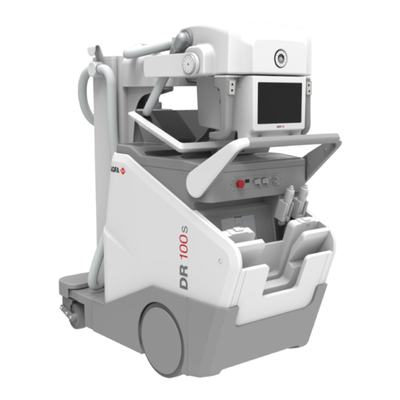
DR 100s | Introduction | 17 Configuration DR 100s is an integrated mobile Digital Radiography X-Ray System. The complete DR 100s consists of the mobile X-ray unit with integrated X-ray generator and NX software and one or more DR detectors. DR 100s has two configurations: •... - Page 18 18 | DR 100s | Introduction Figure 2: DR 100s mobile X-Ray System with manual collimator The DR 100s configurations have two variants of the vertical column: • Telescopic column • Standard column 0411D EN 20220627 1040...
-
Page 19: Operation Controls
DR 100s | Introduction | 19 Operation Controls Storage bin Emergency stop button NX workstation (all-in-one PC) mounted on a mounting bracket The NX workstation displays the NX application and the software console. Lock of the arm movement during transport... - Page 20 20 | DR 100s | Introduction Handlebar with brake lever Interfaces for registering the DR detector or connecting to the network Exposure buttons Topics: • Power on/off button • Battery status indicator • Power controls • Emergency stop button •...
-
Page 21: Power On/Off Button
DR 100s | Introduction | 21 Power on/off button Only authorized operators can power on the system. Depending on the configuration, the operator requires a personal RFID key or a four digit access code to power on the system. Power off button... - Page 22 22 | DR 100s | Introduction Stopping DR 100s on page 95 Managing the RFID reader for user authentication on page 139 Managing the access codes for the on/off keypad on page 135 0411D EN 20220627 1040...
-
Page 23: Battery Status Indicator
DR 100s | Introduction | 23 Battery status indicator Radiation indicator Battery charge level indicators Battery charge level is too low to make further exposures. Drive the unit to the nearest location where the battery can be charged. Related Links... -
Page 24: Power Controls
24 | DR 100s | Introduction Power controls Power supply cable reel Equipotential node Circuit breaker Figure 5: Power controls The equipment is protected by a circuit breaker against excessive mains fluctuations. To restore operation of the equipment after activation of the circuit breaker, return the switch to position "I". -
Page 25: Emergency Stop Button
DR 100s | Introduction | 25 Emergency stop button Figure 6: Emergency stop button If a system malfunction causes an emergency situation involving the patient, operating personnel or any system component, activate the emergency stop. All motor driven movements will be stopped. -
Page 26: Nx Workstation (All-In-One Pc)
26 | DR 100s | Introduction NX Workstation (all-in-one PC) The NX application is available on the all-in-one PC that is mounted on the X- ray system. The PC is operated by touchscreen. To connect USB accessories, use the USB ports on the front panel of the X-ray system. -
Page 27: Worklist Window
DR 100s | Introduction | 27 Worklist window Figure 8: Worklist Window In the Worklist window, you can view and manage the exams that are scheduled and that have been performed. 0411D EN 20220627 1040... -
Page 28: Examination Window
28 | DR 100s | Introduction Examination window Figure 9: Examination window In the Examination window, you can view and manage the details of a specific examination. The drop-down list in the title bar of the window shows the name of the patient for which the examination is performed. You can select another name from the list to display the examination of the patient. -
Page 29: Editing Window
DR 100s | Introduction | 29 Editing window Figure 10: Editing window In the Editing window, you can prepare the image for printing. 0411D EN 20220627 1040... -
Page 30: Main Menu Window
30 | DR 100s | Introduction Main Menu window Figure 11: Main Menu window In the Main Menu window, you can manage certain aspects of the NX Workflow which do not belong to the daily workflow. 0411D EN 20220627 1040... -
Page 31: Software Console
DR 100s | Introduction | 31 Software Console The software console is available to support X-ray exposure control on the NX workstation. It is displayed on the NX workstation next to the NX application. The software console is used to control the X-ray exposure settings. -
Page 32: Tube Head Display
32 | DR 100s | Introduction Tube head display The tube head display can be used to control X-ray exposure settings. It displays the system status. The tube head display contains the DR detector switch. Figure 13: Example: generator controls on the tube head display... -
Page 33: Dr Detector Switch
DR 100s | Introduction | 33 DR detector switch The DR detector switch is available in the X-ray modality status frame of the software console. The DR detector switch shows which DR detector is active and shows its status. The DR detector switch can be used to activate another DR Detector. -
Page 34: Portable Dr Detector
34 | DR 100s | Introduction Portable DR detector When performing an exposure, keep in mind the following detector orientation aids: Table 3: Orientation aids Tube side icon, indicating the side that faces the X- ray tube Patient orientation marker, red rectangle printed at... -
Page 35: Storage Bin
DR 100s | Introduction | 35 Storage bin Emergency stop button Connectors for the hospital network, DR detectors and accessories Exposure button Wireless exposure button (optional) Lock to secure the DR Detector (large format, optional) Integrated charger for DR Detector battery (optional) -
Page 36: Automatic Collimator
36 | DR 100s | Introduction Automatic Collimator Touchscreen display Longitudinal collimation Rails to insert a DAP meter or a filter. Measurement tape to measure the source image distance (SID). The measurement tape is at the rear side of the collimator. -
Page 37: Collimator Camera
DR 100s | Introduction | 37 Collimator camera The collimator can be equipped with a camera to visualize the anatomical region of interest. Figure 16: Location of the camera’s in the collimator The live camera image is visible on the tube head display or on the NX workstation in the software console. - Page 38 38 | DR 100s | Introduction Live camera image Camera button Figure 18: Live camera image on the Examination window Camera images are used for live display only and are not stored. Related Links Measuring the source-image-distance (SID) on page 109...
-
Page 39: Manual Collimator
DR 100s | Introduction | 39 Manual Collimator Longitudinal collimation Button to switch on the light field indicating the collimated area and the laser light indicating the center position. After pressing the button, they remain lit for half a minute before automatically switching off. -
Page 40: Led Beacon Light
40 | DR 100s | Introduction Led beacon light Figure 19: Led beacon light (green) Table 4: Led beacon light Color Meaning The system is not ready for making an exposure. Green The wireless DR Detector and the X-ray generator are ready for mak- ing an exposure. -
Page 41: Exposure Button
DR 100s | Introduction | 41 Exposure button Exposure button Collimator light button Step 1: preparation of the X-ray tube Step 2: exposure Figure 20: Exposure button 0411D EN 20220627 1040... -
Page 42: Wireless Exposure Button
42 | DR 100s | Introduction Wireless exposure button The wireless exposure button is optional. Exposure button Collimator light button Touch sensor Status indicators Led beacon light Figure 21: Wireless exposure button and its holder The operating range of the wireless exposure button is 10m. Check the wireless environment beforehand for conditions that may cause a communications error, e.g. - Page 43 DR 100s | Introduction | 43 Name Color Meaning BATT Battery charge level is low. The battery of the wireless ex- posure button must be replaced as soon as possible. Battery charge level is very low. The battery of the wireless exposure button must be replaced immediately.
-
Page 44: Barcode Reader
44 | DR 100s | Introduction Barcode reader The barcode reader setup includes following components : • A battery powered barcode reader • A charging stand connected to power outlet to store the barcode reader and charge the battery. Status LED The LED is flashing amber while charging. -
Page 45: Connectors For The Hospital Network, Dr Detectors And Accessories
DR 100s | Introduction | 45 Connectors for the hospital network, DR detectors and accessories IR Data Communication Unit for registering a DR Detector. Network connector to connect the NX workstation to the hospital network. Network connector to connect the Registration Cable for registering a DR Detector. -
Page 46: Messages
46 | DR 100s | Introduction Messages Under certain conditions the system shows a dialog box in the middle of the screen containing a message, or a message is displayed in a fixed message area in the user interface. This message informs the user that either a problem has occurred or that a requested action cannot be performed. -
Page 47: Labels
DR 100s | Introduction | 47 Labels Topics: • General • Type label • DR Detector identification label • Labeling of the collimator 0411D EN 20220627 1040... -
Page 48: General
48 | DR 100s | Introduction General Always take into account the markings and labels provided on the inside and outside of the machine. A brief overview of these markings and labels and their meaning is given below. Figure 24: Circuit breaker Table 7: Circuit breaker Circuit breaker on and off positions. - Page 49 DR 100s | Introduction | 49 Figure 25: Interfaces for registering the DR detector or connecting to the network Table 8: Interfaces for registering the DR detector or connecting to the network USB connector. Network connector to connect the Registration Cable for registering a DR Detector.
- Page 50 50 | DR 100s | Introduction Figure 26: Exposure buttons Table 9: Exposure buttons Exposure button Figure 27: Pinch points Table 10: Pinch points Follow the instructions in the user manual. General hazard. Pinch points. 0411D EN 20220627 1040...
- Page 51 DR 100s | Introduction | 51 Figure 28: Front bumper Table 11: Front bumper Follow the instructions in the user manual. The operator, the patient or any other person shall not climb on the bumper. Don't lay objects on the bumper.
- Page 52 52 | DR 100s | Introduction Table 12: Locks to secure the DR Detector Lock to secure the DR Detector Following warning is printed next to the power on/off button, in English: WARNING: This x-ray unit may be dangerous to patient and operator unless safe exposure factors, operating instructions and maintenance schedules are observed.
- Page 53 DR 100s | Introduction | 53 Serial number of the X-ray tube (only for 40 kW configuration) Figure 31: Labels at the back of the tube head 0411D EN 20220627 1040...
-
Page 54: Type Label
54 | DR 100s | Introduction Type label X-ray system Figure 32: Example of type label X-ray generator and X-ray tube assembly Figure 33: Example of type label The 21 CFR Subchapter J label is posi- tioned close to the type label. - Page 55 DR 100s | Introduction | 55 Manufacturer Date of manufacture Type number Serial number This mark shows compliance of the equip- ment with Directive 93/42/EEC (for Euro- pean Union). This symbol on the products, and/or ac- companying documents means that used...
-
Page 56: Dr Detector Identification Label
56 | DR 100s | Introduction DR Detector identification label Label Meaning Writable label to identify and dedicate a DR Detector to an X- ray system bucky. 0411D EN 20220627 1040... -
Page 57: Labeling Of The Collimator
DR 100s | Introduction | 57 Labeling of the collimator The type label is located at the rear side Figure 34: Example of type label of the collimator. (A) Laser openings (B) Warning labels Avoid exposure. Radiation is emitted from this opening. -
Page 58: Installation
58 | DR 100s | Introduction Installation Installation and configuration is performed by an Agfa trained and authorized service engineer. Contact your local support organization for more information. Use the equipment only in rooms or areas that comply with all applicable laws (or regulations having the force of law), referring to the electrical safety of this type of medical device. -
Page 59: Labeling The Dr Detectors
DR 100s | Introduction | 59 Labeling the DR Detectors CAUTION: Selecting the wrong DR detector can cause the need to retake the image. On a configuration with multiple wireless DR Detectors of the same type, it is required to apply labeling to the DR Detector containing a unique nickname for each DR Detector. -
Page 60: Equipotential Earth Connection
60 | DR 100s | Introduction Equipotential earth connection The device is supplied with an equipotential earth connection point. The device can only be used in areas that comply with local electrical safety norms and in environments suitable for medical activities. -
Page 61: Electrostatic Discharge
DR 100s | Introduction | 61 Electrostatic discharge CAUTION: Always resort to static procedures, protections and appropriate products before opening or during the handling of the equipment. This equipment includes electrostatically sensitive components. Non-compliance with electrostatic discharge procedures may cause damages to the components. Such damages to the components are not covered by any warranty. -
Page 62: Radiation Protection
62 | DR 100s | Introduction Radiation Protection X-ray radiation can cause serious damage to the health, therefore observe great care and ensure that protection against X-ray exposure is always applied. Some of the effects of X-ray radiation are cumulative and may extend over a period of time. -
Page 63: Monitoring Of Personnel
DR 100s | Introduction | 63 Monitoring of Personnel The monitoring checks the amount of X-ray radiation the personnel has been exposed to. It determines safety of the operators and it helps checking if safety measures of the X-ray environment are adequate. Inadequate or improper protection can lead to serious damage to the health. -
Page 64: Effect Of Sid On Patient Dose
64 | DR 100s | Introduction Effect of SID on patient dose Changing the distance of the X-ray tube to the patient affects the dose applied to the patient. For example doubling the distance reduces the dose by a factor of 4. The new dose can be calculated by a formula: new mAs = known mAs ×... -
Page 65: Cleaning And Disinfecting
DR 100s | Introduction | 65 Cleaning and Disinfecting All appropriate policies and procedures should be followed to avoid contamination of the user/staff, patients and other equipment. All necessary precautions shall be taken to avoid patient contact or contact with potential sources of contamination. -
Page 66: Cleaning
66 | DR 100s | Introduction Cleaning To clean the exterior of the equipment: 1. Stop the system. WARNING: When the equipment is going to be cleaned, be sure to turn OFF the power of each device, and to unplug the power cord from the AC outlet. - Page 67 DR 100s | Introduction | 67 Cleaning enameled or aluminum parts Enameled parts and aluminum surfaces must be cleaned only with a damp cloth and a mild detergent and then with a dry woolen cloth. Never use scouring powders, solvents, abrasives detergents or polishing abrasive. Do not use a special detergent if its properties are not sure.
-
Page 68: Disinfecting
If you plan to use other disinfectants, approval of Agfa is needed before use, as most disinfectants can damage the device. UV disinfection is also not allowed. Perform the procedure following the instructions for use, the disposal instructions and the safety instructions of the selected disinfectants and tools and of the hospital. -
Page 69: Disinfecting Safety Directions
DR 100s | Introduction | 69 Disinfecting safety directions WARNING: Using a disinfectant that can form an explosive or flammable gas mixtures is hazard to life and health because of explosion risk. Switch the equipment off before disinfecting. Allow the gas mixture to evaporate before switching the x-ray system back on. -
Page 70: Approved Disinfectants
70 | DR 100s | Introduction Approved disinfectants Refer to the Agfa website for specifications on the disinfectants that have been found compatible with the cover material of the device and can be used on the outer surface of the device. -
Page 71: Patient Data Security
DR 100s | Introduction | 71 Patient data security The user must ensure that the patients’ legal requirements are met and that the security of the patient data is guarded. The user must define who can access patient data in which situations. -
Page 72: Maintenance
There are two levels of maintenance, the first consists of tasks which are performed by the user/operator, and the second are those tasks to be performed by qualified X-ray service personnel. Always consult the Agfa Service documentation and an AGFA trained and authorized Service engineer for complete maintenance schedules. Topics: •... -
Page 73: Preventive Maintenance Schedule
DR 100s | Introduction | 73 Preventive maintenance schedule The user must ensure that all checks are performed satisfactorily before using the equipment for its intended purpose. Table 13: Preventive maintenance by the user Interval What to do? Daily Check for defective lights, components, nameplates and damaged warning signals, main cables and connectors. -
Page 74: Maintenance Of The Batteries
74 | DR 100s | Introduction Maintenance of the batteries The batteries require regular checks by trained and competent service personnel, in order to ensure a correct functioning of the equipment and a long lasting of batteries. The batteries require following actions by the user for correct maintenance: •... -
Page 75: Training
The user must make sure that training is received in accordance with local laws or regulations that have the force of law. Your local Agfa or dealer representative can provide further information on training. The user must note the following information in the system documentation: •... -
Page 76: Safety Directions
Safety is only guaranteed when changes, additions, maintenance or repairs are carried out by an Agfa certified field service engineer. A non certified engineer performing a modification or service intervention on a medical device, acts on his own responsibility and makes the warranty void. - Page 77 DR 100s | Safety Directions | 77 and adequate training can cause serious or mortal physical injuries or wrong diagnosis or therapies. WARNING: Do not use the device with patients if there is no adequate understanding of its capabilities and functions. Using the device...
- Page 78 78 | DR 100s | Safety Directions WARNING: Do not connect the equipment with anything other than specified. Doing so may result in fire or electric shock. WARNING: To avoid risk of electric shock, do not remove any covers. Changes, additions, maintenance or repairs must be carried out by an Agfa certified field service engineer.
- Page 79 DR 100s | Safety Directions | 79 WARNING: Always double check your exposure parameter settings prior to exposing the patient. CAUTION: Avoid unnecessary dose by checking before exposure if the DR Detector Switch displays the name of the DR Detector that is being used and if the status of the DR Detector is ready for exposure.
-
Page 80: Basic Workflow
80 | DR 100s | Basic Workflow Basic Workflow Topics: • Starting DR 100s • Driving the unit • Starting the examination • Positioning the DR detector • Positioning the X-ray tube • Checking the exposure settings • Executing the exposure •... -
Page 81: Starting Dr 100S
DR 100s | Basic Workflow | 81 Starting DR 100s 1. Unplug the unit from the mains power. 2. Unlock the device. • To unlock the device using the RFID reader, put your personal RFID key on the RFID reader. - Page 82 X-ray tube has not been in use for more than an hour. This extends the X-ray tube lifetime. The DR 100s can be operated in two different ways: connected to a wired network or using a wireless network.
-
Page 83: Automated Workflow For Warming-Up Of X-Ray Tube
DR 100s | Basic Workflow | 83 Connectors for the hospital network, DR detectors and accessories on page 45 Managing the RFID reader for user authentication on page 139 Managing the access codes for the on/off keypad on page 135... -
Page 84: Driving The Unit
84 | DR 100s | Basic Workflow Driving the unit WARNING: Exceeding speed while driving from a ramp. To drive from a ramp safely, reduce the speed by intermittently releasing the drive handle. WARNING: The uncontrolled movement of the equipment could cause damages to the operator, patient and personnel in proximity of it. - Page 85 DR 100s | Basic Workflow | 85 Locking bar • Push the handlebar softly with both hands to drive forward. • Pull the handlebar softly with both hands to drive backward. • The speed is proportional to the stress on the handle for the transport.
-
Page 86: Starting The Examination
86 | DR 100s | Basic Workflow Starting the examination 1. Press the brake control at the tube-collimator handles and move the X-ray tube head upward. The arm is released from secured position. The display of the NX workstation and of the tube head light up. -
Page 87: Positioning The Dr Detector
DR 100s | Basic Workflow | 87 Positioning the DR detector 1. If a grid is used for the examination, attach the grid to the detector. 2. Wrap the DR detector in a protective plastic bag. WARNING: Liquids ingressing the DR Detector may cause malfunction and contamination. -
Page 88: Positioning The X-Ray Tube
88 | DR 100s | Basic Workflow Positioning the X-ray tube WARNING: Monitor with special care the patient position or anyone present, to avoid injury caused by unit movements. Intravenous tubing, catheters and other patient connected lines should be routed away from moving equipment. - Page 89 DR 100s | Basic Workflow | 89 Pivot clockwise Pivot counterclockwise Move forward Move backward Figure 41: Movement control buttons The forward and backward directions assume the viewpoint of the operator facing the X-ray tube head while the vertical column is rotated 180°, e.g.
-
Page 90: Checking The Exposure Settings
90 | DR 100s | Basic Workflow Checking the exposure settings 1. Check if the DR Detector Switch displays the name of the DR Detector that's being used a) If a wrong DR Detector is displayed, select the right DR Detector by clicking the drop down arrow on the DR Detector Switch. -
Page 91: Executing The Exposure
DR 100s | Basic Workflow | 91 Executing the exposure 1. Take a safe distance from the X-ray tube. CAUTION: Excessive user or operator radiation exposure. Always keep a distance of at least 2 meters from the focal spot and X-ray beam, protect body and do not expose hands, arms or other parts of the body to the primary beam. -
Page 92: Using The Wired Exposure Button
92 | DR 100s | Basic Workflow Using the wired exposure button Completely extend the cable of the exposure button and keep as far as possible from the radiation source. The cable of the exposure button can be extended up to 4 m. Stretching it further can damage the cable. -
Page 93: Using The Wireless Exposure Button
DR 100s | Basic Workflow | 93 Using the wireless exposure button The wireless exposure button is optional. Ensure that there is no other equipment with remote control nearby. Keep as far as possible from the radiation source. The wireless exposure button operates at a distance of maximum 11 m from the device at any angle and within sight, through glass or leaded glass. -
Page 94: Performing A Quality Control
94 | DR 100s | Basic Workflow Performing a quality control In NX: 1. Select the image on which quality control is to be performed. 2. Prepare the image for diagnosis by using e.g. L/R markers or annotations. 3. If the image is OK, send the image to a hardcopy printer and/or PACS (Picture Archiving and Communication System). -
Page 95: Stopping Dr 100S
DR 100s | Basic Workflow | 95 Stopping DR 100s WARNING: Use of the equipment by non authorized personnel can cause damages to people or things. Never leave the equipment on and unattended. Switch the equipment off according the correct shutdown procedures. - Page 96 96 | DR 100s | Basic Workflow Check if the catch has successfully locked the X-ray tube head, by trying to push it upward without touching the brake controls. 2. Lock the device. • To lock the device using the RFID reader, press and hold the power button until the green status indicator light starts blinking.
- Page 97 DR 100s | Basic Workflow | 97 Figure 43: Activating the locks to secure the DR detector. 0411D EN 20220627 1040...
-
Page 98: Charging A Dr Detector Battery
98 | DR 100s | Basic Workflow Charging a DR detector battery Depending on the configuration, the grid holder includes a charger for a specific model of DR detector batteries. To charge a DR detector battery: 1. Insert the battery in the charger. - Page 99 DR 100s | Basic Workflow | 99 Label Light Status The battery is being charged. Battery charge level 75-100%. Green Battery charging is completed. Charge is sufficient to perform examinations. In order to optimize battery lifetime, it is recommen- ded not to leave the battery permanently powered by the charger.
-
Page 100: Charging The Dr 100S Battery
CAUTION: To charge the battery, place the system in a well-ventilated area. Charging the DR 100s battery can be started any time, regardless if the system is on or off. While the battery is charging, all motorized functions of the system are disabled. -
Page 101: Automatically Switching Off The Dr 100S
DR 100s | Basic Workflow | 101 Automatically switching off the DR 100s The DR 100s switches off automatically after a specific time since the last exposure. The time is 30 minutes by default and can be configured from 4 to 60 minutes by an authorized service engineer. -
Page 102: Stopping Nx By Logging Out Of Windows
102 | DR 100s | Basic Workflow Stopping NX by logging out of Windows 1. Go to the Main Menu. 2. Click the Log Off button. Figure 45: Log Off buton 3. The third step. As a result: • NX is closed. -
Page 103: Guidelines For Pediatric Applications
The user documentation of this product contains a set of guidelines for pediatric applications, applicable in the U.S.A. Refer to document "Exposure Techniques for pediatric and adult use with DR 100s". 0411D EN 20220627 1040... -
Page 104: Software Console
104 | DR 100s | Software Console Software Console The software console is displayed on the NX workstation. On a configuration with tube head display, the software console is displayed on the tube head display as well. The arrangement and availability of the controls may be slightly different. -
Page 105: Action Buttons
DR 100s | Software Console | 105 Action buttons Table 17: Action buttons Icon Description Button to switch on the light field indicating the collimated area. Button to switch on the laser light indicating the center position and the source image distance (SID). -
Page 106: Planned Exposures
106 | DR 100s | Software Console Planned exposures By clicking the status bar, an overview is displayed of the exposures that still have to be taken for the examination. Select an exposure to load the default X-ray exposure parameters and to activate the selected DR Detector. -
Page 107: Dr Detector And X-Ray Tube Head Alignment
DR 100s | Software Console | 107 DR detector and X-ray tube head alignment The examination overview screen can show a readout of the tilting angle of the DR detector and of the X-ray tube head. The relative angle between the DR detector and the horizon- tal surface. -
Page 108: Live Camera Image
108 | DR 100s | Software Console Live camera image By clicking an empty thumbnail in the Image Overview pane of the Examination window, the live camera image is displayed on the tube head display and on the software console. -
Page 109: Measuring The Source-Image-Distance (Sid)
DR 100s | Software Console | 109 Measuring the source-image-distance (SID) CAUTION: Moving the system from a cold environment into a heated room may cause condensation to form on the collimator camera’s. In this case, wait until the condensation evaporates before use. - Page 110 110 | DR 100s | Software Console Radiographic parameters Tilting angle of the DR detector and of the X-ray tube head Full screen button Reset button Live camera button Rotate button Transparant green overlay indicating the DR detector reference plane Figure 48: Still image 2.
- Page 111 DR 100s | Software Console | 111 7. If the position of the patient is adjusted, repeat the measurement. a) Press the reset button. Figure 51: Reset button The readouts for the measured SID and patient size are cleared. b) Repeat the above steps to perform a new measurement.
-
Page 112: Dose Adaptation Guidance
112 | DR 100s | Software Console Dose adaptation guidance On a system with a 3D depth camera, the patient size is calculated after measuring the source-image-distance. The optimal dose adaptation setting for the patient is indicated by a blinking orange frame. To apply this setting, press the indicated patient size icon. -
Page 113: X-Ray Image Preview Screen
DR 100s | Software Console | 113 X-ray image preview screen After an exposure, the acquired image is displayed on the tube head display. To return to the controls, push the display anywhere. To disable image preview, toggle the Image preview button. -
Page 114: X-Ray Modality Status Frame
114 | DR 100s | Software Console X-ray modality status frame Ready for exposure status The status bar displays the exam type. Modality position DAP value DR detector switch Filter status Grid status Button to enable or disable the preview of the acquired image... -
Page 115: Ready For Exposure Status
DR 100s | Software Console | 115 Ready for exposure status Table 18: Exposure ready Color Description Green Exposure ready. Indicates that the selected technique is properly set and there are no interlock failures or system faults. Exposure not ready. -
Page 116: Modality Position
116 | DR 100s | Software Console Modality Position The modality position is automatically selected, based on the selected exposure. To modify the position on the mode in which the exposure will be made, navigate to the X-ray modality controls screen and select the modality position. -
Page 117: Dr Detector Switch
DR 100s | Software Console | 117 DR detector switch The DR detector switch is available in the X-ray modality status frame of the software console. The DR detector switch shows which DR detector is active and shows its status. The DR detector switch can be used to activate another DR Detector. -
Page 118: Dr Detector Status
118 | DR 100s | Software Console DR Detector Status Battery status icon Meaning Full Medium Empty Connection status icon (wifi/ wired) Meaning Good Low Bad Wired DR Detector DR detector status icon (blinking) Meaning Ready Initializing expo- Error Sleep One DR detector... -
Page 119: Unknown Status
DR 100s | Software Console | 119 Unknown status If a status is unknown, a question mark icon is displayed: Figure 56: Unknown status Depending on the component for which the unknown status is displayed, an action is required on the component or on the software to provide the system with the missing information. -
Page 120: Filter Status
120 | DR 100s | Software Console Filter Status On systems with automatic filtering, the filter is automatically set, based on the selected exposure. The filter setting can be modified on the software console. Table 20: Collimator with automatic filter (no icon) No filter is used. -
Page 121: Anti-Scatter Grid Status
DR 100s | Software Console | 121 Anti-scatter grid status (no icon) No grid is required. A grid is required. 0411D EN 20220627 1040... -
Page 122: Radiation Status
122 | DR 100s | Software Console Radiation status Table 22: Radiation status Icon Description The X-ray tube is prepared. After pressing the exposure button completely, the X-ray ex- posure is made. The indicator on the console will light up. -
Page 123: Power Status
DR 100s | Software Console | 123 Power status Table 23: Power status Icon Description Battery charge level is critical. No exposure can be made. This status can be overruled by clicking the icon, to allow one more exposure to be made. -
Page 124: Dap Value
124 | DR 100s | Software Console DAP Value The DAP value shows the radiation value of the last exposure. The radiation measure is read as DAP value (Dose Area Product) in cGy*cm (for example: DAP 12.22). This measurement unit is configurable. -
Page 125: Generator Controls
DR 100s | Software Console | 125 Generator controls Radiographic parameters Focal spot indicator Patient size Figure 57: Generator controls To change a value, use the + and - buttons. The values increase or decrease step by step each time the corresponding button is pushed. To change a value without repeatedly pushing the buttons, push the value twice. -
Page 126: Radiographic Parameters
126 | DR 100s | Software Console Radiographic Parameters You can set up following radiographic parameters: • kV: shows the radiographic kV value (X-ray tube voltage) selected for the exposure. • mAs: shows the radiographic mAs value selected for the exposure. -
Page 127: Focal Spot Indicator
DR 100s | Software Console | 127 Focal Spot Indicator A focal spot indicator shows the selected focal spot of the X-ray tube: “Small” or “Large”. Table 24: Focal Spot Indicator Small Large If you change the focal spot, the kV and mAs are kept constant. When... -
Page 128: Patient Size
128 | DR 100s | Software Console Patient Size The size of the patient is classified in five categories: Extra Small, Small, Medium, Large and Extra Large. Press one of the buttons to select the desired patient size. The patient size setting affects the mAs value. -
Page 129: X-Ray Modality Controls
DR 100s | Software Console | 129 X-ray modality controls Select the modality position. Select the DR detector or switch to CR. All configured detectors are displayed. Only the detectors that can be used with the selected modality position, can be selected. -
Page 130: System Messages Screen
130 | DR 100s | Software Console System messages screen System messages are displayed at the bottom of the software console. The color of the message indicates the importance: Blue Information Yellow Warning Orange Error Messages that require feedback from the user contain a button that can be pressed. - Page 131 DR 100s | Software Console | 131 The system messages screen lists all messages since the last startup of the software. Figure 61: Messages history 0411D EN 20220627 1040...
-
Page 132: Advanced Operation
132 | DR 100s | Advanced Operation Advanced Operation Topics: • Hanging a leaded apron • Replacing the battery of the wireless exposure button • Managing the access codes for the on/off keypad • Managing the RFID reader for user authentication •... -
Page 133: Hanging A Leaded Apron
DR 100s | Advanced Operation | 133 Hanging a leaded apron CAUTION: The weight of a leaded apron hanging on the arm or directly on the X-ray tube assembly, could cause uncontrolled movements of the arm and trouble of positioning. Don't hang a leaded apron to the arm. -
Page 134: Replacing The Battery Of The Wireless Exposure Button
When the battery status indictor on the holder of the wireless exposure button lights up orange, the battery must be replaced immediately. Replace the battery of the wireless exposure button while the DR 100s is switched off. 1. Rotate the end cap 90° in the counterclockwise direction. -
Page 135: Managing The Access Codes For The On/Off Keypad
DR 100s | Advanced Operation | 135 Managing the access codes for the on/off keypad One or more access codes can be configured for unlocking the on/off keypad. Power button Status indicator lights Enter button Topics: • Modifying the access code •... -
Page 136: Modifying The Access Code
136 | DR 100s | Advanced Operation Modifying the access code 1. Shut down the system. 2. Press and hold the power button until the green status indicator light starts blinking. 3. Press and hold the enter button until the blue status indicator light starts blinking. -
Page 137: Adding An Extra Access Code
DR 100s | Advanced Operation | 137 Adding an extra access code 1. Shut down the system. 2. Press and hold the power button until the green status indicator light starts blinking. 3. Press and hold the enter button until the blue status indicator light starts blinking. -
Page 138: Deleting An Access Code
138 | DR 100s | Advanced Operation Deleting an access code 1. Shut down the system. 2. Press and hold the power button until the green status indicator light starts blinking. 3. Press and hold the enter button until the blue status indicator light starts blinking. -
Page 139: Managing The Rfid Reader For User Authentication
Each RFID key must be linked to a Windows user account. Multiple RFID keys can be linked to the same Windows user account. An RFID key can be configured on more than one DR 100s system. There are two special types of RFID key: •... -
Page 140: Adding An Rfid Key Card To The Configuration Of The Rfid Reader
1. On the NX workstation, go to the Main Menu. 2. Click the Show Desktop action button. The Windows desktop is shown. 3. Go to the Windows Start menu > Agfa and click RFID Config Tool. The RFID Configuration Tool dialog is displayed. Figure 63: RFID Configuration Tool 4. -
Page 141: Adding A Start-Up Only Rfid Key Card To The Configuration Of The Rfid Reader
1. On the NX workstation, go to the Main Menu. 2. Click the Show Desktop action button. The Windows desktop is shown. 3. Go to the Windows Start menu > Agfa and click RFID Config Tool. The RFID Configuration Tool dialog is displayed. 4. Select the tab Configure Users. -
Page 142: Updating The Configuration Of A User
Use this procedure e.g. to change the Windows password of a user or to replace a lost RFID key. 1. Go to the Windows Start menu > Agfa and click RFID Config Tool. The RFID Configuration Tool dialog is displayed. -
Page 143: Removing An Rfid Key Card From The Configuration Of The Rfid Reader
RFID reader Only users who have a Windows administrator account can perform this task. 1. Go to the Windows Start menu > Agfa and click RFID Config Tool. The RFID Configuration Tool dialog is displayed. 2. Select the user's RFID key from the list of configured RFID keys. -
Page 144: Copying The Configuration Of The Rfid Reader To Another Dr 100S System
1. On the NX workstation, go to the Main Menu. 2. Click the Show Desktop action button. The Windows desktop is shown. 3. Go to the Windows Start menu > Agfa and click RFID Config Tool. The RFID Configuration Tool dialog is displayed. 4. Select the tab Configure Settings. -
Page 145: Dose Area Product Meter (Dap)
DR 100s | Advanced Operation | 145 Dose Area Product Meter (DAP) An integrated DAP meter (Dose Area Product Meter) in the automatic collimator is available as an option. The DAP meter reads the radiation as Dose Area Product in [cGy x cm The measured radiation value is transferred to the Software Console automatically and displayed after each exposure. -
Page 146: Problem Solving
An object is hit while driving forward • The X-ray system cannot be moved • The NX workstation is not powering off when stopping DR 100s • Problem with RFID reader while starting or stopping DR 100s • The equipment cannot be switched off •... -
Page 147: An Object Is Hit While Driving Forward
DR 100s | Problem solving | 147 An object is hit while driving forward Details In case the front bumper hits an object while driving forward, the movement is immediately stopped. Brief Solu- Move the system backward, away from the collision area. -
Page 148: The X-Ray System Cannot Be Moved
148 | DR 100s | Problem solving The X-ray system cannot be moved Details The X-ray system cannot be moved. First Fault in the exposure button (wired or wireless). problem An error is displayed on the software console: “Exposure switch situation error”. - Page 149 DR 100s | Problem solving | 149 Always keep the red metallic unlocking cable pulled. If it is re- leased, the equipment immediately stops. 0411D EN 20220627 1040...
-
Page 150: The Nx Workstation Is Not Powering Off When Stopping Dr 100S
150 | DR 100s | Problem solving The NX workstation is not powering off when stopping DR 100s Details After stopping DR 100s, the NX workstation is not powering off automatically. Wait until the complete shutdown procedure has finished. This may take up to 5 minutes. -
Page 151: Problem With Rfid Reader While Starting Or Stopping Dr 100S
Problem with RFID reader while starting or stopping DR 100s Details The procedure to start or to stop DR 100s does not succeed. The power status indicator light is off or blinking. First problem The power status indicator light is not starting to blink situation when an RFID key is put on the RFID reader. -
Page 152: The Equipment Cannot Be Switched Off
152 | DR 100s | Problem solving The equipment cannot be switched off Details The procedure to stop DR 100s does not succeed. The power status indicator light remains on. Wait until the complete shutdown procedure has finished. This may take up to 5 minutes. -
Page 153: The Visibility Of The Windows Taskbar Is Not Configured Correctly
DR 100s | Problem solving | 153 The visibility of the Windows taskbar is not configured correctly Details The Windows taskbar can be configured to be always visible or to hide automatically. The setting must be configured for each indi- vidual Windows user account. -
Page 154: Bluetooth Connection Of Barcode Reader Is Broken
154 | DR 100s | Problem solving Bluetooth connection of barcode reader is broken Details The bluetooth LED is flashing fast when it has lost connection to the PC. Cause Bluetooth connection fails to pair the barcode device with the PC. -
Page 155: Corner Area Of Detector Not Exposed
DR 100s | Problem solving | 155 Corner area of detector not exposed Details A small area in the corner of the detector has not been ex- posed. Cause When making an exposure with small source-image distance (e.g. 1 m) and with the collimator in rotated position (e.g. -
Page 156: Virtual Keyboard Not Closing
156 | DR 100s | Problem solving Virtual keyboard not closing Details The virtual keyboard reappears right after it's closed. Cause When an editable field is selected, the virtual keyboard cannot be closed using the close button in the top right of the keyboard. -
Page 157: The Locks To Secure The Dr Detectors Cannot Be Released
Details The locks to secure the DR detectors are not released when start- ing DR 100s or when pressing the action button on the software console. The DR detector cannot be removed from the storage bin. Cause Mechanical or software failure. -
Page 158: Dr Detector Must Be Recalibrated
158 | DR 100s | Problem solving DR Detector must be Recalibrated Details A message is displayed on NX indicating that the DR De- tector must be recalibrated. Cause A DR Detector must be recalibrated at regular interval. Brief Solution... -
Page 159: Product Information
DR 100s | Product Information | 159 Product Information Topics: • Accessories • Compatibility • Compliance • Connectivity • Equipment Classification • Product Complaints • Environmental protection • Technical Data • Remarks for HF-emission and immunity 0411D EN 20220627 1040... -
Page 160: Accessories
Compatibility The system must only be used in combination with other equipment or components if these are expressly recognized by Agfa as compatible. A list of such equipment and components is available from Agfa service on request. Changes or additions to the equipment must only be carried out by persons authorized to do so by Agfa. -
Page 161: General
DR 100s | Product Information | 161 General • The product has been designed in accordance with the MEDDEV Guidelines relating to the application of Medical Devices and have been tested as part of the conformity assessment procedures required by 93/42/EEC Medical Device Directive (European Council Directive 93/42/EEC on Medical Devices). -
Page 162: Connectivity
DR 100s communicates with other devices in the hospital network using one of the following protocols: • DICOM • IHE DR 100s can be connected to a RIS system (input scheduling), a PACS system (output image/data management) and to a hardcopy device (output image). Topics: •... -
Page 163: Connecting Usb Devices
DR 100s | Product Information | 163 Connecting USB devices WARNING: Only USB devices powered via the USB cable may be connected to a USB port of the PC of the mobile X-ray system. The use of USB devices powered by an AC/DC power supply is strictly forbidden. -
Page 164: Connecting Dr 100S To A Wired Network
164 | DR 100s | Product Information Connecting DR 100s to a wired network To connect DR 100s to a wired network: 1. Place the unit in secured position. 2. Connect a network cable to the connector for the hospital network and plug it into a network socket. -
Page 165: Equipment Classification
DR 100s | Product Information | 165 Equipment Classification Per EN/IEC60601-1, Medical Electrical Equipment, General Requirements for Safety 3rd Edition, this device is classified as following: Table 27: Equipment classification Class I equip- Equipment in which protection against electric shock does... -
Page 166: Product Complaints
Manufacturer address: Agfa Service Support - local support addresses and phone numbers are listed on www.agfa.com Agfa - Septestraat 27, 2640 Mortsel, Belgium Agfa - Fax +32 3 444 7094... -
Page 167: Environmental Protection
DR 100s | Product Information | 167 Environmental protection Figure 70: WEEE symbol Figure 71: Battery symbol WEEE end user notice The directive on Waste Electrical and Electronic Equipment (WEEE) aims to prevent the generation of electric and electronic waste and to promote the reuse, recycling and other forms of recovery. - Page 168 168 | DR 100s | Product Information For battery replacements please contact your local sales organization. 0411D EN 20220627 1040...
-
Page 169: Technical Data
DR 100s | Product Information | 169 Technical Data Topics: • DR 100s • DAP meter • Automatic collimator • Manual collimator technical data • X-ray group (40 kW configuration) • X-ray group (32 kW configuration) • Wired exposure button •... -
Page 170: Dr 100S
170 | DR 100s | Product Information DR 100s Electrical connection Rated power supply 115 or 230Vac ±10%, 50/60 Hz ± 5 Hz, 10A, standard monophase with ground conductor. Automatic setting of the equipment accord- ing to mains voltage. Automatic line compensation. - Page 171 DR 100s | Product Information | 171 Mechanical specifications Table 28: Dimensions of the system with telescopic column Dimensions All dimensions are in mm. Linear tolerances ±5 mm, angular ±1°. 0411D EN 20220627 1040...
- Page 172 172 | DR 100s | Product Information Dimensions (in secured position) 576 x 1290 x 1364 mm width x length x height 940 - 960 mm Handle height (adjustable by service) Weight 470 kg (without DR detector) 675 mm - 2051 mm...
- Page 173 DR 100s | Product Information | 173 Table 29: Dimensions of the system with fixed column Dimensions All dimensions are in mm. Linear tolerances ±5 mm, angular ±1°. Dimensions (in secured position) 576 x 1290 x 1840 mm width x length x height...
- Page 174 174 | DR 100s | Product Information 940 - 960 mm Handle height (adjustable by service) Weight 475 kg (without DR detector) 660 mm - 1941 mm Focus-floor distance (Z-axis) 2076 mm Maximum height Telescopic arm extension range 360 mm...
- Page 175 DR 100s | Product Information | 175 Environmental conditions Table 30: Environmental conditions of the mobile X-ray unit Environmental conditions (during normal operation) Room temperature between +10 °C and +35 °C Humidity (non condensing) between 30% and 75% RH (non-condensing)
-
Page 176: Dap Meter
176 | DR 100s | Product Information DAP meter Model Diamentor CI-P Type Device for the dose area product meas- urement in X-ray diagnostics according to IEC 60580 standard. Principle of measurement Radiation measure with ionization chamber Measured quantity Dose area product Digital resolution 0.01 cGy x cm... -
Page 177: Automatic Collimator
DR 100s | Product Information | 177 Automatic collimator Model R221 ACS Manufacturer Ralco Via dei Tigli 13/G 20853 Biassono (MB), Italy Collimation Motorized (and manual) with internal light source, multilayer, squared field, double la- ser at overlaid lines for SID control at 100 cm adjustable by service up to 190 cm. -
Page 178: Manual Collimator Technical Data
178 | DR 100s | Product Information Manual collimator technical data Model R108 F Manufacturer Ralco Via dei Tigli 13/G 20853 Biassono (MB), Italy Collimation Manual with internal light source, multi- layer, squared field, laser field to deter- mine the SID at 1 m. -
Page 179: X-Ray Group (40 Kw Configuration)
DR 100s | Product Information | 179 X-ray group (40 kW configuration) Table 31: X-ray specifications Nominal power (IEC 60601-1) 40 kW @ 100 kV, 400 mA kV values 40 - 150 kV at steps of 1 kV Inverter frequency in high voltage... - Page 180 180 | DR 100s | Product Information Table 34: Maximum settable mAs focus small small large large exposure time minimum 0.63 0.63 maximum maximum maximum maximum Table 35: Generator Model HF1 G/29 Maximum power (100 kV - 400 mA) 40 kW...
- Page 181 DR 100s | Product Information | 181 Table 36: X-ray tube assembly Model Maximum voltage to the tube 150 kV Maximum thermal capacity 500 kJ Maximum continuous heat dissipation 120 W Minimum inherent filtration @75 kV 1.2 mm Al Additional filtration 0.3 mm Al...
- Page 182 182 | DR 100s | Product Information Minimum inherent filtration (IEC 522) 0.7 mm Al Thermal capacity of the anode 225 kJ (300 kHU) Maximum continuous anode dissipation 500 W Nominal high voltage 150 kVp 0411D EN 20220627 1040...
-
Page 183: X-Ray Group (32 Kw Configuration)
DR 100s | Product Information | 183 X-ray group (32 kW configuration) Table 38: X-ray specifications Nominal power (IEC 60601-1) 32 kW @ 100 kV, 320 mA kV values 40 - 125 kV at steps of 1 kV mA values @115/230Vac... - Page 184 184 | DR 100s | Product Information Table 41: Maximum settable mAs focus small large small large exposure time minimum 0.63 0.63 maximum maximum maximum maximum 2100 Table 42: Monobloc Model HF1 R/7 ORB Maximum power (100 kV - 400 mA)
- Page 185 DR 100s | Product Information | 185 1 mGy/h Maximum radiation leakage Figure 73: Heating and cooling curves Table 43: X-ray tube Model Rotation speed 3000 min‾¹ Nominal High voltage 130 kVp Nominal focus dim. (IEC 60336) 0.6 mm small focus 1.3 mm large focus...
- Page 186 186 | DR 100s | Product Information CURVE DI CARICO SINGOLO - SINGLE LOAD RATING - ABAQUE DE CHARGE UNIQUE CURVE DI CARICO SINGOLO - SINGLE LOAD RATING - ABAQUE DE CHARGE UNIQUE 0.6 - 3 ~ - 3000 min 1.3 - 3 ~ - 3000 min...
-
Page 187: Wired Exposure Button
DR 100s | Product Information | 187 Wired exposure button Model C2UW-DS Manufacturer Omron Type X-ray control with cable and integrated colli- mator light pushbutton Allowable operating fre- 60 times/min. or less quency Shock (malfunction) 300 m/s Vibration (destruction) Frequency 10 Hz to 55 Hz, double amplitude 1.5 mm... -
Page 188: Wireless Exposure Button
188 | DR 100s | Product Information Wireless exposure button Model C2UW (C2UW-LP-I DA+C2UW-LU DA) Manufacturer Omron Type X-ray remote control bluetooth with integrated col- limator light pushbutton Standard Bluetooth 4.0 Low Energy (SIG certification acquired) Frequency 2.4 GHz zone (2.402 GHz to 2.480 GHz) -
Page 189: Typical Exposure Parameters
DR 100s | Product Information | 189 Typical exposure parameters The default X-ray exposure parameters for each exposure type can be customized. The device is delivered with a set of X-ray exposure parameters that are intended as a guideline. The default X-ray exposure parameters are only starting points that can be replaced by more specific X-ray exposure parameters developed by the operator. - Page 190 190 | DR 100s | Product Information Table 46: Anatomic group for examinations of the upper extremities Anatomic program Focus µGym Clavicle Small 16.81 Humerus Small 8.56 Elbow Small 8.53 Forearm Small 4.27 Wrist Small 3.25 Hand/Fingers Small 1.99 Table 47: Anatomic group for examinations of the lower extremities...
- Page 191 DR 100s | Product Information | 191 Anatomic program Focus µGym Chest 8,0 kg Small 1.08 Abdomen 4,5 kg Small 3.19 Abdomen 8,0 kg Small 5.13 Chest 10 kg Small 2.18 Abdomen 10 kg Small 4.16 Abdomen 15 kg Small 8.36...
-
Page 192: Remarks For Hf-Emission And Immunity
192 | DR 100s | Product Information Remarks for HF-emission and immunity This device was tested for a normal hospital environment. WARNING: The HF-emission and immunity can be influenced by connected data cables depending on length and the manner of installation. - Page 193 DR 100s | Product Information | 193 might not offer adequate protection to radio-frequency communication services. The user might need to take mitigation measures, such as relocating or re-orienting the equipment. Table 51: Guidance and manufacturer's declaration on electromagnetic immunity...
- Page 194 194 | DR 100s | Product Information 6 V in ISM bands 6 V in ISM bands used no closer than from 150 kHz to from 150 kHz to 30 cm to any part of 80 MHz 80 MHz the equipment, in- cluding cables speci- fied by manufacturer.
-
Page 195: Immunity To Rf Wireless Communication Equipment
DR 100s | Product Information | 195 Immunity to RF wireless communication equipment Service ISM Band Distance Immunity test level (MHz) (V/m) 300-390 TETRA 400 430-470 GMRS 460; FRS 460 704-787 LTE Band 13, 17 800-960 GSM 800/900; TETRA 800, IDEN 820;... -
Page 196: Precautions On Emc
196 | DR 100s | Product Information Precautions on EMC WARNING: Use of this equipment adjacent to or stacked with other equipment should be avoided because it could result in improper operation. If such use is necessary, this equipment and the other equipment should be observed to verify that they are operating normally. -
Page 197: Cables, Transducers And Accessories
DR 100s | Product Information | 197 Cables, transducers and accessories Cables, transducers and accessories which were tested and found to comply with the collateral standard IEC60601-1-2 (EMC): CAUTION: Use of accessories, transducers and cables other than those specified or provided by the manufacturer of this equipment... -
Page 198: For U.s.a
198 | DR 100s | Product Information For U.S.A. This device complies with Part 15 of the FCC Rules. Operation is subject to the following two conditions: • This device may not cause harmful interference. • This device must accept any interference received, including interference that may cause undesired operation.
Need help?
Do you have a question about the DR 100s and is the answer not in the manual?
Questions and answers