
Related Manuals for Watson-Marlow qdos H-FLO


Summary of Contents for Watson-Marlow qdos H-FLO
- Page 1 Reference Manual qdos H-FLO Date of publication : Version of publication : Language of publication : December 18 , 2023 v0.5 English...
-
Page 2: Preface
Preface Disclaimer The information contained in this document is believed to be correct but Watson-Marlow accepts no liability for any errors it contains and reserves the right to alter specifications without notice. If the product is used in a way that is not intended or described in these instructions, the protection, performance, and/or lifespan may be negatively affected. -
Page 3: Table Of Contents
Table of Contents Preface ..........................2 Disclaimer ........................... 2 Translation of the original instructions ................. 2 Introduction to the document ..................6 User groups ..........................6 Information types ........................6 Trademarks ..........................6 Safety ..........................7 Product damage—Remove from service ................7 Safety symbols ........................... - Page 4 Installation—Chapter 3: Fluid path ................48 11.1 Part 1: Chapter installation requirements, specification, and information ....48 11.1.1 Fluid path connectors ......................48 11.2 Part 2: Chapter installation procedures ................52 11.3 Part 3: Chapter specific HMI set up ..................55 Installation—Chapter 4 Overview: Control ..............
- Page 5 Operation ........................207 24.1 Pre-operation checklist......................207 24.2 Safety ............................208 24.3 Pump operation........................209 Cleaning .......................... 214 25.1 Overview ..........................214 25.2 General procedure for guidance ..................214 Maintenance ........................215 26.1 Replacement pumpheads ....................215 26.2 Electrical maintenance ......................216 26.3 Pumphead maintenance ......................
-
Page 6: Introduction To The Document
Introduction to the document User groups These instructions are the installation and maintenance instructions, for a Watson-Marlow qdos H-FLO pump, for reference during the products lifecycle by a: User group Definition Responsible Person A person, competent in their aera of expertise, in or acting on... -
Page 7: Safety
Safety Product damage—Remove from service In the event of product damage. The pump must be removed from service by a responsible person. Do not continue to operate the pump. Safety symbols The following safety symbols may be used on the product, packaging and in these instructions: Symbol Name Description... -
Page 8: Safety Signals
Safety signals Signals indicate a possible hazard. Signals are used in these instructions when immediately relevant to the information, task or procedure. 3.3.1 Signals: With risk of personal injury Signals indicating risk of a personal injury are presented when relevant to a task in this format: WARNING The WARNING signal word indicates a hazard. -
Page 9: Responsibility
Responsibility A responsible person must use these instructions to: Ensure the product will be used within the scope of : • Intended Use (see section 4.3) Pumping of flammable liquids (see Section 3.5) • Prior to a task, such as installation, operation or maintenance Do a risk assessment. -
Page 10: Product Overview
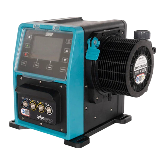
General description A Watson-Marlow qdos pump provides a flowrate of fluid through a fluid path, by the principle of positive displacement from the pumphead. A general illustration is provided below:... -
Page 11: Intended Use
A procedure for checking chemical compatibility is provided in NOTE section 28. Pump models A qdos pump is a combination of • A qdos H-FLO drive A ReNu pumphead • The model variation, general arrangement, and features of each of these components is explained in the following sub-sections. - Page 12 4.4.1 Drive: Model variations qdos H-FLO drive is available in the following model variations: Item Variation Pumphead 2 pumphead mounting models (left or right) mounting variations Control models 6 control models: • Manual only control Manual model (digital start/stop only) Manual, or Analogue or Digital control •...
- Page 13 4.4.2 Drive: General arrangement The general arrangement of a DriveSure drive is illustrated below: Number Description Picture Drive Pumphead Baseplate HMI cover (shown open, resting on top of drive) HMI screen Control connections Pumphead locking lever Power cable...
- Page 14 4.4.3 Pumphead: Model variations There are 2 different pumphead types. Pumphead Application ReNu SEBS Optimised for sodium hypochlorite, and sulphuric acid applications ReNu Santoprene General purpose with great chemical compatibility across a range of applications...
- Page 15 4.4.4 Pumphead: General arrangement The general arrangement of a pumphead is provided in the image below Normally wetted by Number Name pumped fluid Discharge fluid path ■ Discharge fluid connector ■ Connection collar Pumphead discharge fluid connection port ■ Pumphead inlet fluid connection port ■...
-
Page 16: Accessories
The M12 4W (4 wire) control cable is for the manual model only The pressure sensing kit will be available for purchase Q1, 2024. The kit NOTE includes the relevant control cable . Do not fit any devices or accessories other than those approved by Watson-Marlow or as specified in these instructions... -
Page 17: Product Labels
Product labels Number Name Picture Symbol: refer to these instructions Safety symbol QR code for instructions Product Range/Model Control connection labels Product manufacturer Compliance symbols Ingress protection rating Product serial number label location Disposal Symbol (not household waste) Earth bond test point A/C Power supply requirements... -
Page 18: Product Code Guide
Product code guide The product model may be identified from its product code . The drive and pumphead each have a separate product code. These product codes are explained in the subsections below. 4.7.1 Drive product code Model Input/Output Pumphead Power plug connectors orientation... -
Page 19: Specification
Specification 4.8.1 Performance 4.8.1.1 Flowrate and discharge pressure Flow rates in the table below are based on pumping water at 20 °C in a 0 bar inlet and discharge pressure application Discharge Flow rate pressure Min. Max. Max. USGPH USGPH Pumphead ReNu 150 Santoprene 0.12... - Page 20 4.8.1.2 Performance curve The flowrate versus application pressure of a under the following conditions is shown in the performance curves in this section.: Pumping water at 20 °C • Maximum pumphead speed (rpm) • Inlet pressure PSI Discharge pressure PSI Inlet pressure bar Discharge pressure bar...
- Page 21 Ingress protection IP66, NEMA4X Chemical compatibility is dependent on temperature. A procedure for checking NOTE chemical compatibility is provided in section 28. Under certain conditions the pump is suitable for limited outdoor use. Contact NOTE your Watson-Marlow representative for advice.
- Page 22 4.8.2.2 Dimensions 276.0 10.866 35.0 1.378 224.0 8.819 260.0 10.236 33.7 1.327 291.5 11.476 380.0 14.961 118.7 4.673 334.3 13.161 394.2 15.520 332.3 13.083 482.0 18.976...
- Page 23 4.8.2.3 Weight Drive: M type Weight Model Manual 11.6 25.57 Universal 11.7 25.79 Universal+ 11.7 25.79 PROFIBUS 11.7 25.79 EtherNet/IP 11.7 25.79 PROFINET 11.7 25.79 Drive: T type Weight Model Universal 11.8 26.01 Universal+ 11.8 26.01 Pumphead Weight Model ReNu 150 pumphead Santoprene 5.73 ReNu 300 pumphead Santoprene 5.73...
- Page 24 4.8.3 Electrical power specification Item Specification Power supply voltage/Frequency Alternating Current (~100 V to 240 V AC 50/60 Hz) Maximum voltage fluctuation ±10 % of nominal voltage Overvoltage category Rated power 350 VA, 330 W...
- Page 25 4.8.4 Control specification 4.8.4.1 Speed increment Item Specification Speed adjustment range 1900:1 Minimum drive shaft adjustment speed increment 2184:1 4-20 mA resolution NOTE 4-20 mA resolution is only applicable to the Universal and Universal+ models 4.8.4.2 Control feature summary table The control features of a qdos pump are summarised in the table below.
- Page 26 Control Manual Universal Universal+ EtherNet/IP PROFIBUS PROFINET methods Auto restart ● ● ● ● ● ● (after power restored) Fluid recovery ● ● ● ● ● ● Leak detection ● ● ● ● ● ● 5” (127 mm) ● ● ●...
- Page 27 4.8.4.3 Start up defaults Option Default Auto Restart Auto Keypad Lock Pin Protection Asset Number 123465789A Label for Pump WATSON-MARLOW Mode: Manual Manual Run Hours Volume Counter (L) Analog Scaling Factor 1.00 Flow calibration value 32.29...
-
Page 28: Hmi Overview
HMI Overview The HMI is a TFT display with keys. The keys are used to access the menus to configure or operate the pump. Information relating to the HMI key and menus is explained in the table below: Item Method Select Words highlighted in BLACK... - Page 29 4.9.1 HMI layout A summary of the key function is provided below: Number Name Summary Colour TFT display HMI display with backlight. Flow calibration Key activates flow calibration mode +/- Keys Keys are used to change programmable values or move the selection bar up or down in the menus.
- Page 30 4.9.2 HOME screen The HOME screen is the main screen showing the last selected operating mode in Manual Mode. This screen is accessed using the HOME key. An example of a HOME screen in Manual Mode is shown below. Home Screen: (Manual mode) Item Description Indicates menu selection.
- Page 31 4.9.3 INFO screen The INFO screen should inform the user of the configuration of the drive. It is accessible even when pin protection is active. The info screen is accessible from the home screen of the drive in any mode using the INFO key. An example of the INFO screen is shown below.
- Page 32 4.9.4 MAIN MENU overview The MAIN MENU is the highest level menu. All features, functionality and settings are accessible through this menu and subsequent sub-menus. The main menu screen is shown below. MAIN MENU Screen: Item Description User selected sub menus. Menu selection.
- Page 33 4.9.5 MODE MENU overview The MODE menu lists the available modes. Access to the MODE menu is through soft key 1 when the option is highlighted. If required, the settings will be available through soft key 2 when the option is highlighted. MODE MENU Screen: Item Description SELECT enables access to selected mode...
-
Page 34: Storage
Storage Storage conditions Storage temperature range: -20 °C to 70 °C (-4 °F to 158 °F) • Indoors • Not in direct sunlight • Humidity (non-condensing): 80 % up to 31 °C (88 °F), decreasing linearly to 50 % at 40 °C •... -
Page 35: Lifting And Carrying
Lifting and carrying Product in packaging The drive and pumphead are not supplied in the same packaging. The weight is as follows: 6.1.1 Packed Weight 6.1.1.1 Drive: M type Packed weight Model Manual 14.8 32.63 Universal 14.9 32.85 Universal+ 14.9 32.85 PROFIBUS 14.9... -
Page 36: Product Removed From Packaging
Product removed from packaging If the product has been removed from the packaging: Do not lift the pump by the top of the HMI. • • Obey the following safety signals CAUTION Lifting or moving the pump with the pumphead installed may result in the pumphead disengaging from the drive and falling. -
Page 37: Unpacking
Unpacking Components supplied A H-FLO drive and pumphead are sold separately. The components supplied with each part are detailed below 7.1.1 Drive The drive will come with the following items included within the packaging • Chosen model of drive unit •... -
Page 38: Unpacking, Inspection And Packaging Disposal
Carefully remove all parts from the packaging. Check that all components in "7.1 Components supplied" are present Inspect components for damage in transit. If anything is missing or damaged, contact your Watson-Marlow representative immediately. Dispose of the packaging according to local procedures. -
Page 39: Installation-Overview
Installation—Overview Responsibility Installation must only be undertaken by a responsible person competent in their area of expertise to the installation chapter. Using the HMI for installation The use of the HMI will be required to set up the pump during installation. Review the HMI overview of screens, key operation and menus, in section 4.9 prior to carrying out an installation task. -
Page 40: Installation-Chapter 1: Physical
Ingress protection IP66, NEMA4X Chemical compatibility is dependent on temperature. A procedure for NOTE checking chemical compatibility is provided in section 28. Under certain conditions the pump is suitable for limited outdoor use. NOTE Contact your Watson-Marlow representative for advice. - Page 41 Additional clearance will be required for the: mm (4.53 in) Installation of control cables • • Open and close the HMI cover Operate and view the screen and keypad. • If the pump is to be installed inside an enclosure, contact your Watson-Marlow representative for advice.
- Page 42 9.1.2.3 Surface and orientation The pump must be installed as follows in accordance with the illustrations and explanations table below: On a surface: Number Information Install the pump on a level surface. NOTICE A mounting slope can cause poor lubrication, resulting in damage to the pump though accelerated wear.
- Page 43 9.1.3 Pump mounting dimensions The dimensions for mounting the pump are provided by the illustration and table below Dimension Letter 10.87 1.38 8.82 10.24 0.43 0.55 The mounting slots are designed to accommodate an anchorage fixing not NOTE larger than a M8 bolt with a minimum 15 mm OD M8 flat washer.
-
Page 44: Part 2: Chapter Installation Procedures
Part 2: Chapter installation procedures 9.2.1 Chapter pre-installation checklist Carry out the following pre-installation checklist prior to following the installation procedure below: 1. Ensure all requirements of part 1 of this chapter have been met. 2. Ensure the pump has not yet been connected to electrical power, the fluid path, or the control system. -
Page 45: Installation-Chapter 2: Electrical Power
Installation—Chapter 2: Electrical power 10.1 Part 1: Chapter installation requirements, specification, and information 10.1.1 Power specification requirements Only connect to an earthed single phase power supply which meets the specification in the table below: Item Specification Power supply voltage/Frequency Alternating Current (~100 V to 240 V AC 50/60 Hz) Maximum voltage fluctuation ±10 % of nominal voltage Overvoltage category... -
Page 46: Part 2: Chapter Installation Procedures
10.2 Part 2: Chapter installation procedures 10.2.1 Chapter pre-installation checklist At this stage of the installation sequence, the pump should be physically installed, with no power, and the fluid path or control system not yet connected. Prior to electrical power installation, carry out the following pre-installation check to ensure: •... - Page 47 10.2.3 Procedure: Connecting to the power supply 1. Complete the pre-installation checklist provided in the section 10.2.1 2. Ensure the power cable plug socket outlet is isolated from the power supply. 3. Ensure the electrical power supply disconnecting device is easy to reach and operate for electrical power isolation when required.
-
Page 48: Installation-Chapter 3: Fluid Path
All other drive product codes are supplied with the BSP fluid connectors. 11.1.2 Ancillary devices A Watson-Marlow pump should be installed into a fluid path system with specific ancillary devices to ensure safe operation. These requirements are detailed in the sections below. All devices, connections or pipework must be: •... - Page 49 11.1.2.2 Overpressure safety device A Watson‑Marlow pump operates by positive displacement. Should a blockage or restriction occur, the pump will continue to operate until either of the following occur: • The pumphead tubing or element, or ancillary device may rupture, leak or otherwise fail The fluid path pipework or ancillary device, may rupture, leak or otherwise fail •...
- Page 50 11.1.3 Inlet and discharge pipework 11.1.3.1 General Inlet and discharge pipes should be should: • Be as short as possible • Be as direct as possible • Follow the straightest route • Use bends of large radius • With the largest diameter bore tube that will fit with your process. 11.1.3.2 Flow calibration In order to carry out a flow calibration, the discharge pipework system will need to be designed to allow pumping into a graduated container near the pump.
- Page 51 11.1.3.4 Safety overflow All pumphead models have a hose barb safety overflow, as illustrated below In the unlikely event of a leak detection sensor failure, the safety overflow provides a safe leak path for mixture of fluid and lubricant. The pumphead has a factory fitted rubber cap on the safety overflow, which is unplugged, but not removed during installation of the safety overflow.
-
Page 52: Part 2: Chapter Installation Procedures
11.2 Part 2: Chapter installation procedures 11.2.1 Chapter pre-installation checklist Prior to installing the fluid path carry out the following pre-installation check to ensure: Pump has been installed in accordance with installation chapter 1, and 2 • All requirements of part 1 of this chapter have been met •... - Page 53 9. Apply electrical power to pump. Pump will enter into its first time start up sequence and the Watson-Marlow logo will display for three seconds. 10. The screen below will be displayed to allow selection of the on screen text language.
- Page 54 12. Press CONFIRM to continue. 13. To change your selection, press REJECT 14. Press start and run pumphead for a few revolutions. 15. Stop pump. 16. Isolate the pump from the electrical power supply. 17. Check the locking lever is still correctly locked in position. If not: Isolate pump from electrical supply •...
-
Page 55: Part 3: Chapter Specific Hmi Set Up
11.3 Part 3: Chapter specific HMI set up 11.3.1 HMI—Setting the flow units: general settings>flow units After the fluid path is installed the flowrate from the pump should be calibrated. Prior to fluid calibration the preferred flow units should be selected in general settings using the HMI. From the MAIN MENU:... - Page 56 11.3.2 HMI—Calibrating the pump flowrate: MODE menu>Flow calibration MODE Menu using the +/- keys, Flow calibration can be accessed from either the or using the Flow calibration key. 11.3.2.1 To calibrate pump flowrate: 1. Enter the Flow Calibration menu from the MODE menu by pressing SELECT...
- Page 57 5. Press START to begin pumping a volume of fluid for calibration. 6. Press STOP to stop pumping fluid for the calibration. 7. Using the +/- keys enter the actual volume of fluid pumped. 8. Pump now calibrated. ACCEPT RE-CALIBRATE to repeat procedure.
- Page 58 11.3.2.2 Abort flow calibration 1. Press HOME or MODE to abort calibration. 2. This advice screen will be displayed. Press BACK CONFIRM to continue.
- Page 59 11.3.2.3 Troubleshooting flow calibration The following advice screens may appear during calibration. To clear, use either CONTINUE RE-CALIBRATE...
-
Page 60: Installation-Chapter 4 Overview: Control
Installation—Chapter 4 Overview: Control The control chapter is split into the following sub-chapters based upon model Sub-Chapter 4A: Manual model Sub-Chapter 4B: Universal and Universal+ models Sub-Chapter 4C: PROFIBUS model Sub-Chapter 4D: EtherNet/IP model Sub-Chapter 4E: PROFINET model Follow the sub-chapter based upon your model. 12.1 Sub-Chapter wiring diagram key The following key is used in all Chapter 4 sub chapters... -
Page 61: Installation-Sub-Chapter 4A: Control (Model: Manual)
Installation—Sub-Chapter 4A: Control (Model: Manual) This section provides information on connection, input/output specification and relevant set up using the HMI of the Manual model only. 13.1 Part 1: Sub-Chapter installation requirements, specification, and information 13.1.1 Control connections 13.1.1.1 Input/Output signal limits Limits Parameter Units... - Page 62 Watson-Marlow Accessory: Item Product code Qdos H-FLO Control cable - Manual I/O M12A 4W Cable 0M9.603Z.0EF Straight F Connection, 3m (10ft) Length, Unshielded 24 AWG. Qdos H-FLO Control cable - Manual I/O M12A 4W Cable 0M9.603Z.0FF...
- Page 63 13.1.1.3 Wiring information—Control input: Start/Stop Function Signal Configurable Wiring Diagram Pin 1 24 V DC START/STOP START/STOP Pin 2 (+) 0 = [0 V to 9.2 V DC] 1 = [10.4 V to 30 V DC] Pin 3 No user connection Pin 4 (-) 0 V Common...
-
Page 64: Part 2: Sub-Chapter Installation Procedures
13.2 Part 2: Sub-Chapter installation procedures 13.2.1 Sub-Chapter pre-installation checklist Prior to installing the control connections and wiring carry out the following pre-installation check: Ensure the pump has been installed in accordance with installation chapter 1, 2 and 3 • Ensure all requirements of part 1 of this chapter have been met •... -
Page 65: Part 3: Sub-Chapter Specific Hmi Set Up
13.3 Part 3: Sub-Chapter specific HMI set up The sub-sections below provide information on manual model only related set up of the pump using the HMI. 13.3.1 HMI—Setting the start/stop: control settings>input A start/stop signal can be used to stop the pump using the remote stop feature. This will not effect the following operation: Flow calibrations •... - Page 66 7. Press SELECT 8. Use +/- keys to highlight options 9. Press SELECT to enable HIGH or LOW polarity 13.3.1.2 To configure start/stop: Assign input The start/stop cannot be assigned to any other input than #4.
-
Page 67: Installation-Sub-Chapter 4B: Control (Models: Universal And Universal+)
Installation—Sub-Chapter 4B: Control (Models: Universal and Universal+) 14.1 Sub-Chapter overview This section provides information on connection, input/output specification and relevant set up using the HMI of the Universal and Universal+ models only. 14.2 Part 1: Sub-Chapter installation requirements, specification, and information 14.2.1 Chemical metering: Analog: 4-20 mA, or Pulse? Both a Universal and Universal+ pump can be used for chemical metering, using 2 primary... - Page 68 14.2.2 Connection type overview There are two types of input and output control connections for the Universal and Universal+ models: Product Name Description Location code M type with M12 control Product codes connections containing M T type with user wired Product codes cable gland containing T...
- Page 69 14.2.3 Control signal limits The control signal limits are provided in the table below, this information applies to all Universal and Universal+ models (M and T types). Limits Parameter Units Comment Sym Min Nom 24V IEC 61131-2 Type 3 Digital Input voltage High 10.4 Digital Input Voltage Low Digital Input Abs Max voltage...
- Page 70 Watson-Marlow Accessory: Item Product code Qdos H-FLO Control cable - General I/O M12A 8W Cable 0M9.603Z.0CF Straight F Connection, 3m (10ft) Length, Unshielded 24AWG Qdos H-FLO Control cable - General I/O M12A 8W Cable 0M9.603Z.0DF...
- Page 71 14.2.4.2 Wiring Information—Control input (Universal only) The following information applies to the Universal model only for the control input #1 connection Configurab Function Signal Wiring Diagram Pin 1 24 V DC INPUT 1 INPUT 1 Pin 2 (+) 0 = [0 V to 9.2 V DC] 1 = [10.4 V to 30 V DC] INPUT 2 INPUT 2...
- Page 72 14.2.4.3 Wiring Information—Control input (Universal+ only) The following information applies to the Universal+ model only for the control input #1 connection Function Signal Configurable Wiring Diagram Pin 1 24 V DC INPUT 1 INPUT 1 Pin 2 (+) 0 = [0 V to 9.2 V DC] 1 = [10.4 V to 30 V DC] INPUT 2 INPUT 2...
- Page 73 Function Signal Configurable Wiring Diagram OUTPUT 4-20mA OUT SPEED Pin 5 (+) Common shared connection with OUTPUT#1 Pin5 Pin 6 (-) 0 V Common ANALOG 1M 4-20mA#1M Pin 7 (+) Analogue 1 - Reference/Pass through (Floating ground) START/STOP Stop = High ►...
- Page 74 Watson-Marlow Accessory: Item Product code Qdos H-FLO Control cable - General I/O M12A 8W Cable 0M9.603Z.0CF Straight F Connection, 3m (10ft) Length, Unshielded 24AWG Qdos H-FLO Control cable - General I/O M12A 8W Cable 0M9.603Z.0DF...
- Page 75 14.2.4.5 Wiring Information—Control output #1 connection (Universal only) The following information applies to the Universal model only for the control output #1 connection. Function Signal Configurable Wiring Diagram RELAY1-NC Pin 2 24 V 1 A DC Resistive RELAY 1 RELAY1-COM Pin 3 24 V 1 A DC Resistive RELAY1-NO...
- Page 76 14.2.4.6 Wiring Information—Control output #1 connection (Universal+ only) The following information applies to the Universal+ model only for the control output #1 connection. Function Signal Configurable Wiring Diagram RELAY1-NC Pin 2 24 V 1 A DC Resistive RELAY 1 RELAY1-COM Pin 3 24 V 1 A DC Resistive RELAY1-NO...
- Page 77 Watson-Marlow Accessory: Item Product code Qdos H-FLO Control cable - General I/O M12A 8W Cable 0M9.603Z.0CF Straight F Connection, 3m (10ft) Length, Unshielded 24AWG. Qdos H-FLO Control cable - General I/O M12A 8W Cable 0M9.603Z.0DF...
- Page 78 14.2.4.8 Wiring Information—Control output #2 connection (Universal only) The following information applies to the Universal model only for the control output #2 connection. Function Signal Configurable Wiring Diagram RELAY3-NC Pin 2 24 V 1 A DC Resistive RELAY 3 RELAY3-COM Pin 3 24 V 1 A DC Resistive RELAY3-NO...
- Page 79 14.2.4.9 Wiring Information—Control output #2 connection (Universal+ only) The following information applies to the Universal+ model only for the control output #2 connection. Function Signal Configurable Wiring Diagram RELAY3-NC Pin 2 24 V 1 A DC Resistive RELAY 3 RELAY3-COM Pin 3 24 V 1 A DC Resistive RELAY3-NO...
- Page 80 14.2.4.9.1 Overview—Control input: Pressure sensor (Universal and Universal+) A pressure sensor input connection is provided, for use with the Watson-Marlow Pressure Sensor Kit on both the Universal and Universal+ models. It is not possible to use a third party pressure sensor.
- Page 81 14.2.5 T Type (user wired cable gland connections) 14.2.5.1 Overview—T-type connections Location The terminal board is located behind the input/ouput panel on T type models Connection IP66, NEMA 4X Specification Control Parameter Data NOTE 1 NOTE 2 cable specification Terminal Wire Size 24 AWG to 12 AWG M2.5 Screw 240 V 5 A AC...
- Page 82 14.2.5.2 Wiring information—T type connections The layout of the terminal board is provided in the illustration below: Function Signal Wiring Diagram Stop = High ► Pin 1 0 = [110 AC] STOP (AC) ■ 1 = [0 V AC] AC-INPUT Stop = Low Pin 2 ■...
- Page 83 Function Signal Wiring Diagram Pin 1 Stop = High (AC) ► 0 = [110 AC] INPUT-3 ■ 1 = [0 V AC] AC-INPUT Stop = Low Pin 2 ■ 0 = [0 V AC] (AC) ► 1 = [110 V AC] J10 re-label Pin 1 24 V DC...
- Page 84 Function Signal Wiring Diagram Pin 1 24 V DC START/STOP START/STOP Stop = High ► 0 = [0 V to 9.2 V DC] ■ Pin 2 1 = [10.4 V to 30 V DC] Stop = Low ■ 0 = [0 V to 9.2 V DC] ►...
- Page 85 Function Signal Wiring Diagram 4-20mA#1P ANALOGUE Analogue 1+ input 4 to 20 mA Positive Input. Pin 2 (+) [150R] = Pin 1 24 V DC INPUT 1 INPUT 1 Pin 2 (+) 0 = [0 V to 9.2 V DC] 1 = [10.4 V to 30 V DC Pin 3 24 V 100 mA DC...
- Page 86 Function Signal Wiring Diagram INPUT 4 INPUT 4 Pin 1 (+) 0 = [0 V to 9.2 V DC] 1 = [10.4 V to 30 V DC] Pin 2 24 V 100 mA DC INPUT 2 INPUT 2 Pin 3 (+) 0 = [0 V to 9.2 V DC] 1 = [10.4 V to 30 V DC] RELAY1-NO...
- Page 87 Function Signal Wiring Diagram RELAY1-NC Pin 3 240 V 5 A AC Resistive RELAY2-NO Pin 1 240 V 5 A AC Resistive RELAY 2 RELAY2-COM Pin 2 240 V 5 A AC Resistive RELAY2-NC Pin 3 240 V 5 A AC Resistive RELAY3-NO Pin 1 240 V 5 A AC Resistive...
-
Page 88: Part 2: Sub-Chapter Installation Procedures
14.3 Part 2: Sub-Chapter installation procedures 14.3.1 Sub-Chapter pre-installation checklist Prior to installing the control connections and wiring carry out the following pre-installation check: Ensure the pump has been installed in accordance with installation chapter 1, 2 and 3 • Ensure all requirements of part 1 of this chapter have been met •... - Page 89 14.3.3 Installation of M12 control cables (M type) 14.3.3.1 Protective caps The M12 control connections are covered with protective caps during manufacture If any of the connections will not be used for control, leave the protective caps in place of a control cable for added protection of the product. A picture of the cap is illustrated in the picture: 14.3.3.2 M12 control cable installation procedure Follow the procedure below to connect the M12 control cables.
- Page 90 14.3.4 Installation of user wired control cables (T type) 14.3.4.1 Removal and refitting of front input and output panel In order to connect the cables to the terminals of the input output circuit board, the pump module cover must be removed and re-installed after wiring. Follow the procedure below. Isolate the pump from its power supply.
- Page 91 16. Hold relay module cover in place and tighten six M3 x 10 Pozidrive screws.
-
Page 92: Part 3: Sub-Chapter Specific Hmi Set Up
14.4 Part 3: Sub-Chapter specific HMI set up The sub-sections below provide information on control related set up of the pump using the HMI. Not all control settings or MODE menu items are explained here. For full information on: • Mode Menus: See section 22 Control settings: See section 23 •... - Page 93 14.4.1 CHANGE MODE>Analog 4-20 mA In this operating mode the pump speed (flowrate) is proportional to external mA signal input received. Model Speed versus mA signal behaviour Universal model Signal Pump speed 4.1 mA Minimum speed (0 rpm) 19.8 mA Maximum speed (depends on pump head) Universal+ model Relationship between external mA signal and flow rate determined by...
- Page 94 14.4.1.2 Effect of speed limit The speed limit function in control settings will also scale the analog signal. The speed limit function takes precedence over the scaling factor. Speed limit cannot exceed high flow rate set point (B). For more information on the speed limit setting see section 23.1.1 14.4.1.3 Select Analog 4-20 mA mode 1.
- Page 95 14.4.1.4 Calibrate the pump for 4-20 mA control (Universal+ only) The universal+ model can be calibrated for minimum and maximum speed versus minimum and maximum mA signal. There are two methods in the procedure below: Method Summary Manually enter a signal figure using the +/- keys. Manual Input Apply a signal, then select to confirm the figure.
- Page 96 Setting a high signal: 1. MANUAL—Enter value using +/- keys. INPUT—Send high signal input to pump. ACCEPT option displays when high 4-20 mA signal is within tolerance: Press ACCEPT to set input or, CANCEL to return to previous screen...
- Page 97 Setting high flow calibration: 7. Use +/- keys to scroll to choose flow rate: Select SET FLOW BACK to return to previous screen. Setting a low signal 8. MANUAL—Enter value using +/- keys INPUT—Send low signal input to pump. If range between low and high signal is less than 1.5 mA, error message displayed. ACCEPT option displays when low 4-20 mA signal is within tolerance: ACCEPT...
- Page 98 Setting low flow calibration 10. Use +/- keys to choose flow rate: SET FLOW BACK to return to previous screen When all settings are entered, the calibration confirmation screen is displayed. Select either ANALOG to use proportional mode or, MANUAL to use manual mode.
- Page 99 14.4.2 CHANGE MODE>Contact mode Contact mode provides the ability to deliver a user defined dose volume between 0.1 mL and 999 L. This dose can be delivered by one of two methods: Method Summary Manual dose When the START key is pressed. This manual dose can only be delivered if an analogue does is not being delivered at the same time.
- Page 100 14.4.2.1 Procedure: Enable and configure contact mode Enable contact mode Contact Highlight from menu Press SETTINGS to enable Contact Mode and allow editing of values To configure contact mode settings Referring to the Contact Mode Settings table, use +/- keys to enter a value for each setting.
- Page 101 When complete, press FINISH save screen will display. Press SAVE to store data Press DISCARD to return to previous page.
- Page 102 14.4.2.2 Procedure: View Contact home screen. Once Contact mode is enabled and configured, easily view Contact mode home screen and settings via MODE button. To view Contact mode home screen: Press MODE key Use +/- keys to highlight Contact option Press SETTINGS The contact mode home screen will display.
- Page 103 14.4.3 Control settings>Configure inputs The following inputs can be configured in control settings: Item Summary Start/Stop Configure polarity Contact Configure polarity, assign input Fluid recovery Configure polarity, assign input Input 1 and 2 may also be configured in relation to floating ground, as a sub- NOTE menu.
- Page 104 14.4.3.2 To configure start/stop: Polarity A start/stop signal can be used to stop the pump using the remote stop feature. This will not effect the following operation: Flow calibrations • Max speed key operation • Manual Fluid recovery • The polarity of the voltage to start/stop can be set. A low polarity signal is recommended as the pump will stop if an input signal is lost.
- Page 105 Press SELECT Use +/- keys to highlight options Press SELECT to enable HIGH or LOW polarity 14.4.3.3 To configure start/stop: Assign input The start/stop cannot be assigned to any other input than #4.
- Page 106 14.4.3.4 To configure Contact dose start trigger: Polarity The polarity of the voltage to trigger the start of a contact dose can be set. A dose will only be delivered if the pump is in contact mode. 1. Highlight Configure option.
- Page 107 14.4.3.5 To configure Contact dose: Assign input The contact dose trigger can be assigned to be on any of the 4 inputs. 1. Highlight the desired input number. SELECT...
- Page 108 14.4.3.6 To configure fluid recovery polarity 1. Highlight Configure option. SELECT 3. Use +/- keys to highlight options SELECT High or low polarity.
- Page 109 14.4.3.7 To configure Fluid recovery: Assign input Fluid recovery can be assigned to be on any of the 4 inputs. 1. Highlight the desired input number. SELECT...
- Page 110 14.4.4 Control settings>Configurable outputs 14.4.4.1 To configure outputs: 1. Highlight the Configure outputs option. SELECT To configure outputs 1 to 4: Use +/- keys to highlight required option Press SELECT Tick symbol indicates current selection Choose pump status of selected output. Use +/- keys to highlight required option.
- Page 111 Press SELECT Programme selected input Use +/- keys to highlight required l ogic sta tus option Press SELECT Press SELECT to program output Press BACK to cancel...
- Page 112 14.4.4.2 Control settings 4 – 20 mA output (Universal+ model only) The universal+ model only has a 4-20 mA output which can be configured. There are two options Scale Explanation Full scale 4-20 mA output is based on pumps full speed range. 0 rpm Maximum rpm 4 mA...
- Page 113 14.4.5 Control settings>Scaling factor The 4-20 mA profile is a linear relationship where Y=mX+c. The scaling factor is a control setting that can be used to multiply the gradient (m) by a factor. Example shown in graph and table below: Flowrate % Scaling factor Scaling...
- Page 114 14.4.5.2 Effect on Analog 4-20 mA mode: A and B points The scaling factor • Will not alter stored A and B points, set i n An a l o g 4- 2 0 m A m ode • Speed limit cannot exceed high flow rate set point (B). 14.4.5.3 To configure scaling factor: Main Menu use +/- to select...
- Page 115 Toggle Action Enabled Floating ground Disabled Grounded at pump Contact your local Watson-Marlow representative if more information is required.
- Page 116 14.4.6.1 Set floating ground From the MAIN MENU Use +/- keys to highlight CONTROL SETTINGS Press SELECT Highlight Floating ground option. Press SELECT Use +/- keys to highlight required input Press Soft Key 1 to ENABLE DISABLE floating ground Press BACK to display CONTROL SETTINGS...
-
Page 117: Installation-Sub-Chapter 4C: Control (Model: Profibus)
• Diagnostic information it can pass to PROFIBUS master on interrogation. • The GSD file may be downloaded from the Watson-Marlow website from the link below: Web address: https://www.wmfts.com/en/literature/other-resources/software-and-devices/ Dataflow to/from pump may need to be byte-reversed, due to handling data between suppliers of master devices. - Page 118 15.2.3 Control connections The M12 control connections function by location, thread style, pin count and plug code vary. 15.2.3.1 Network connection Overview Two network connections are provided for the PROFIBUS models. Both connections have an identical function. Both PROFIBUS connectors are joined internally to allow flexible network configurations.
- Page 119 M12, Male, 4 Pin, A-code plug, IP66, NEMA 4X Pin out No pin out information is provided. This pressure sensor connection must information only be used with the Watson-Marlow pressure sensor kit. Do not connect any other wires, or cables or attempt to wire to this connection.
- Page 120 15.2.4 Units used in the PROFIBUS parameters The following units are used in the PROFIBUS parameters Name Explanation Example DeciRPM 1/10 of an RPM 1205 deciRPM = 120.5 rpm uL (microlitre) 1/1000 of a mL 1,000,000 uL/min = 1000 mL/min = 1 L/min 15.2.5 User parameter data User Parameter Data Ext_User_Prm_Data_...
- Page 121 15.2.5.3 Set Minimum/Maximum speeds Min/Max Speed parameters are used to set Min/Max speed from PROFIBUS interface: Values must only be used if matching bit in Control Word is enabled and not zero. • Values are 16 bit unsigned in deci RPM (1/10th of pumphead RPM). •...
- Page 122 15.2.6 PROFIBUS data exchange PROFIBUS data exchange Default address PROFIBUS Ident 0x0E7D GSD File WAMA0E7D.GSD Config 0x62, 0x5D (3 words out, 14 words in) User parameter bytes 15.2.6.1 Cyclic Data Write (from Master to pump) Data type Byte order Description 16 bit Byte 1 (high), 2 (low) Control Word...
- Page 123 15.2.6.5 Cyclic Data Read (from pump to master) Data type Byte order Description 16 bit Byte 1 ( high ), 2 ( low ) Status word 16 bit Byte 3 ( high ), 4 ( low ) Pumphead measured speed 16 bit Byte 5 ( high ), 6 ( low ) Hours run...
- Page 124 15.2.7 Device-related diagnostic data Device related diagnostic information is provided in the table below: Bit type Byte order Description Byte 1, 2, 3, 4, 5, 6 Mandatory Slave Byte 8 bit Byte 7 Header byte 8 bit Byte 8 Pump model 8 bit Byte 9 Pump Head...
-
Page 125: Part 2: Sub-Chapter Installation Procedures
15.3 Part 2: Sub-Chapter installation procedures 15.3.1 Sub-Chapter pre-installation checklist Prior to installing the control connections and wiring carry out the following pre-installation check: Ensure the pump has been installed in accordance with installation chapter 1, 2 and 3 • Ensure all requirements of part 1 of this chapter have been met •... - Page 126 15.3.3 Installation of M12 control cables (M type) 15.3.3.1 Protective caps The M12 control connections are covered with protective caps during manufacture If any of the connections will not be used for control, leave the protective caps in place of a control cable for added protection of the product. A picture of the cap is illustrated in the picture: 15.3.3.2 M12 control cable installation procedure Follow the procedure below to connect the M12 control cables.
- Page 127 15.3.4 Master slave communications sequence 15.3.4.1 Data exchange In PROFIBUS mode, the screen below is displayed, the P indicates data exchange is happening. This screen will only be displayed after successful implementation of Master Slave communications, which always follow the sequence described below. Master Slave communications sequence Power On Reset Power ON/reset of Master or Slave...
- Page 128 15.3.4.2 Loss of data exchange If data exchange is lost at any time, the following screen will be displayed. The first red dot corresponds to the stage at which the error occurred, and subsequent stages will indicate a red dot because the communication sequence halted before this point. The screen will state running or stopped, depending on how the user has set up the fail-safe function within the PROFIBUS GSD file.
-
Page 129: Part 3: Sub-Chapter Specific Hmi Set Up
15.4 Part 3: Sub-Chapter specific HMI set up The sub-sections below provide information on PROFIBUS only related set up of the pump using the HMI. For full information on: Mode Menus: See section 22 • • Control settings: See section 23 15.4.1 Procedure: Select and enable PROFIBUS To select and enable PROFIBUS mode: Press MODE key... - Page 130 PROFIBUS home screen shows white icon to indicate data exchange. Pressing INFO displays pump information screen...
- Page 131 15.4.2 Procedure: Assigning the PROFIBUS station address at the pump The station address cannot be automatically assigned by master. 15.4.2.1 To assign PROFIBUS station address Press MODE key Use +/- keys to highlight PROFIBUS SELECT Use +/- keys to edit station address.
- Page 132 Choose FINISH to set station address PROFIBUS Communication NEXT to select When FINISH is selected the save settings screen will be displayed: Select SAVE to store settings...
-
Page 133: Installation-Sub-Chapter 4D: Control (Model: Ethernet/Ip)
Part 1: Sub-Chapter installation requirements, specification, and information 16.1.1 EDS File The EDS file may be downloaded from the Watson-Marlow website from the link below: Web address: https://www.wmfts.com/en/literature/other-resources/software-and-devices/ 16.1.2 Control cable specification A category 5e. shielded ethernet cable, IP66 rated, with a M12 connector is required to connect... - Page 134 16.1.3 Connections The M12 control connections function by location, thread style, pin count and plug code vary. 16.1.3.1 Network connection Overview Two network connections are provided for the EtherNet/IP model. Both connections have an identical function. Location The connections are located as illustrated by the graphic. Specification M12, Female, 4 Pin, D-code socket, IP66, NEMA 4X Pin out...
- Page 135 M12, Male, 4 Pin, A-code plug, IP66, NEMA 4X Pin out No pin out information is provided. This pressure sensor connection must information only be used with the Watson-Marlow pressure sensor kit. Do not connect any other wires, or cables or attempt to wire to this connection.
- Page 136 16.1.4 EtherNet/IP parameters 16.1.4.1 Units used in the EtherNet/IP parameters The following units are used in the EtherNet/IP parameters Name Explanation Example DeciRPM 1/10 of an RPM 1205 deciRPM = 120.5 rpm uL (microlitre) 1/1000 of a mL 1,000,000 uL/min = 1000 mL/min = 1 L/min 16.1.4.2 Network parameters The network parameters for communication of the pump with the network, are pre- programmed during production:...
- Page 137 16.1.4.3 Cyclic parameters The table below lists the Ethernet IP cyclic parameters and the functionality available through the interface ADI Name Access Type Description SetSpeed Write UInt16 Speed set in Deci RPM. Max speed depends on head type. See Pump Head enumeration table SetSpeedLimit Write...
- Page 138 ADI Name Access Type Description Control bitfield Write Unit16 Bit 0 = Set fail safe enable, Enabled the failsafe speed. If disabled, pump will stop in the event of a communications loss. If enabled, pump will run at the speed set in the “SetFailsafeSpeed”...
- Page 139 ADI Name Access Type Description Error Bitfield byte 1 Read Unit32 Bit 0 = Leak detected, Leak detect signal high requires clearing and acknowledging before pump can resume. Bit 1 = Motor Stall error active, If set, pump has a Motor Stall Error. Follow onscreen instructions Bit 2 = Motor Speed error.
- Page 140 ADI Name Access Type Description Error Bitfield byte 3 Read Unit32 Bit 0 = Reserved Voltage Error Bit 2 = Over Temperature Error Bit 3 = Software Fault. If set, there is a software fault Bit 4 = Hardware Fault. If high, there is an Inverter Gate Drive Fault Bit 5 = Power supply over power error Status bit field...
- Page 141 16.1.4.4 Drive model enumeration table Drive model Abbreviation Enum QDOS H-FLO 16.1.4.5 Pumphead enumeration table Maximum Description Enum speed (DeciRPM) ReNu 150 pumphead Santoprene / PFPE 7 bar (102 psi) 1300 ReNu 300 pumphead Santoprene / PFPE 5 bar (73 psi)
-
Page 142: Part 2: Sub-Chapter Installation Procedures
16.2 Part 2: Sub-Chapter installation procedures 16.2.1 Sub-Chapter pre-installation checklist Prior to installing the control connections and wiring carry out the following pre-installation check: Ensure the pump has been installed in accordance with installation chapter 1, 2 and 3 • Ensure all requirements of part 1 of this chapter have been met •... - Page 143 16.2.3 Installation of M12 control cables (M type) 16.2.3.1 Protective caps The M12 control connections are covered with protective caps during manufacture If any of the connections will not be used for control, leave the protective caps in place of a control cable for added protection of the product. A picture of the cap is illustrated in the picture: 16.2.3.2 M12 control cable installation procedure Follow the procedure below to connect the M12 control cables.
-
Page 144: Part 3: Sub-Chapter Specific Hmi Set Up
16.3 Part 3: Sub-Chapter specific HMI set up The sub-sections below provide information on EtherNet/IP only related set up of the pump using the HMI. For full information on: Mode Menus: See section 22 • • Control settings: See section 23 16.3.1 Procedure: Select EtherNet/IP mode using the To select EtherNet/IP mode: Press MODE key... - Page 145 16.3.2 Procedure: Set IP address using the HMI Configuring the IP address can be undertaken by two methods: Method 1: Set static IP Address (manual, DHCP disabled) • • Method 2: Set dynamic IP Address (automatic, DHCP enabled) 16.3.2.1 Procedure: Method 1: Static IP address. By default, DHCP is enabled.
- Page 146 NEXT to move to next value When final value is entered, choose ENTER to commit setting. Setting the Subnet mask and Gateway address follow the same procedure as the IP address. To set the Subnet mask and Gateway address repeat steps 3 to 7.
- Page 147 16.3.2.2 Procedure: Method 2: Set dynamic IP Address (automatic, DHCP enabled) DHCP is enabled by default, it is only necessary to re-enable DHCP if it was previously disabled when an IP address was manually set. Highlight the DHCP setting Ensure that DCHP is Enabled A DHCP server within the network will allocate the drive an IP address based on the MAC address.
- Page 148 16.3.3 Network status screens If the pump is not running and connections are made to ports, the IP address is assigned, and the drive is connected to master. The status screen of this will be shown below: If the pump is not running with no connections made to ports, the IP address is not assigned, and the drive is not connected to master.
-
Page 149: Installation-Sub-Chapter 4E: Control (Model: Profinet)
Part 1: Sub-Chapter installation requirements, specification, and information 17.1.1 GSDML File The GSDML file may be downloaded from the Watson-Marlow website from the link below: Web address: https://www.wmfts.com/en/literature/other-resources/software-and-devices/ 17.1.2 Control cable specification A category 5e. shielded PROFINET cable, IP66 rated, with a M12 connector is required to... - Page 150 17.1.3 Connections The M12 control connections function by location, thread style, pin count and plug code vary. 17.1.3.1 Network connection Overview Two network connections are provided for the PROFINET model. Both connections have an identical function. Location The connections are located as illustrated by the graphic. Specification M12, Female, 4 Pin, D-code socket, IP66, NEMA 4X Pin out...
- Page 151 M12, Male, 4 Pin, A-code plug, IP66, NEMA 4X Pin out No pin out information is provided. This pressure sensor connection must information only be used with the Watson-Marlow pressure sensor kit. Do not connect any other wires, or cables or attempt to wire to this connection.
- Page 152 17.1.4 PROFINET Parameters 17.1.4.1 Units used in the PROFINET parameters The following units are used in the EtherNet/IP parameters Name Explanation Example DeciRPM 1/10 of an RPM 1205 deciRPM = 120.5 rpm uL (microlitre) 1/1000 of a mL 1,000,000 uL/min = 1000 mL/min = 1 L/min 17.1.4.2 Network parameters The network parameters for communication of the pump with the network, are pre- programmed during production:...
- Page 153 17.1.4.4 Cyclic parameters The table below lists the PROFINET cyclic parameters and the functionality available through the interface ADI Name Access Type Description Module Set pump Write UInt16 Speed set in Deci RPM. Max Pump Control speed speed depends on head (deciRPM) type.
- Page 154 ADI Name Access Type Description Module Control bitfield Write Unit16 Bit 0 = Set fail safe enable, Pump Control Enabled the failsafe speed. If disabled, pump will stop in the event of a communications loss. If enabled, pump will run at the speed set in the “SetFailsafeSpeed”...
- Page 155 ADI Name Access Type Description Module Error Bitfield Read Unit32 Bit 0 = Leak detected, Leak Errors and byte 1 detect signal high requires Warnings clearing and acknowledging before pump can resume. Bit 1 = Motor Stall error active, If set, pump has a Motor Stall Error.
- Page 156 ADI Name Access Type Description Module Error Bitfield Read Unit32 Bit 0 = Reserved Errors and byte 3 Warnings Bit 1 = Under Voltage Error Bit 2 = Over Temperature Error Bit 3 = Software Fault. If set, there is a software fault Bit 4 = Hardware Fault.
- Page 157 17.1.4.7 Acyclic parameters The table below lists the PROFINET acyclic parameters and the functionality available through the interface ADI Name Access Type Description Module Pump Model Read UInt8 Displays currently drive (Enum) model See Drive model enumeration table Asset Read Unsigned8 Read pump Asset number...
-
Page 158: Part 2: Sub-Chapter Installation Procedures
17.2 Part 2: Sub-Chapter installation procedures 17.2.1 Sub-Chapter pre-installation checklist Prior to installing the control connections and wiring carry out the following pre-installation check: Ensure the pump has been installed in accordance with installation chapter 1, 2 and 3 • Ensure all requirements of part 1 of this chapter have been met •... - Page 159 17.2.3 Installation of M12 control cables (M type) 17.2.3.1 Protective caps The M12 control connections are covered with protective caps during manufacture If any of the connections will not be used for control, leave the protective caps in place of a control cable for added protection of the product. A picture of the cap is illustrated in the picture: 17.2.3.2 M12 control cable installation procedure Follow the procedure below to connect the M12 control cables.
-
Page 160: Part 3: Sub-Chapter Specific Hmi Set Up
17.3 Part 3: Sub-Chapter specific HMI set up The sub-sections below provide information on PROFINET only related set up of the pump using the HMI. For full information on: Mode Menus: See section 22 • • Control settings: See section 23 17.3.1 Procedure: Select PROFINET mode using the HMI To select EtherNet/IP mode: Press MODE key... - Page 161 17.3.2 Procedure: Set IP address using the HMI Configuring the IP address can be undertaken by two methods: Method 1: Set static IP Address (manual, DHCP disabled) • • Method 2: Set dynamic IP Address (automatic, DHCP enabled) 17.3.2.1 Procedure: Method 1: Static IP address. By default, DHCP is enabled.
- Page 162 When final value is entered, choose ENTER to commit setting. Setting the Subnet mask and Gateway address follow the same procedure as the IP address. To set the Subnet mask and Gateway address repeat steps 3 to 7.
- Page 163 17.3.2.2 Procedure: Method 2: Set dynamic IP Address (automatic, DHCP enabled) DHCP is enabled by default, it is only necessary to re-enable DHCP if it was previously disabled when an IP address was manually set. Highlight the DHCP setting Ensure that DCHP is Enabled by pressing ENABLE A DHCP server within the network allocates the drive an IP address based on the MAC address.
- Page 164 17.3.3 Network status screens If the pump is not running and connections are made to ports, the IP address is assigned and the drive is connected to master. The status screen of this will be shown below: If the pump is not running with no connections made to ports, the IP address is not assigned and the drive is not connected to master.
-
Page 165: Hmi Set Up: Overview
HMI set up: Overview The set up of the HMI is split into the following sections based upon the main menu order: Section 19: HMI set up: Fluid level monitor Section 20: HMI set up: Security settings Section 21: HMI set up: General settings Section 22: HMI set up: MODE menu Section 23: HMI set up: Control settings Follow the sub-chapter based upon your requirement. -
Page 166: Hmi: Fluid Level Monitor
HMI: Fluid level monitor Fluid level monitor i s a cc e s s e d from t h e MAIN MENU using the +/- keys. All models feature a fluid level monitor to monitor the fluid level (quantity) remaining in the inlet supply vessel during operation. -
Page 167: To Enable/Disable The Fluid Level Monitor
19.1 To enable/disable the Fluid level monitor Fluid Level Monitor MAIN MENU. Choose from Use the +/- keys to highlight options. Enable level monitor will already be highlighted. Press ENABLE HOME Fluid volume level will display on screen hoose DISABLE to deactivate the fluid level monitor. -
Page 168: To Change Fluid Volume Unit Of Measure
19.2 To change fluid volume unit of measure: Fluid V o l u m e U n i t FLUID LEVEL SETTINGS. Choose from key to toggle between US GALLONS LITRES 19.3 To configure the level monitor: Choose Configure Level Monitor Press SELECT Use +/- keys to enter maximum volume of supply container. - Page 169 Use +/- keys to set Alert Level. FLUID LEVEL SETTINGS Press SELECT to return to...
-
Page 170: To Adjust Fluid Volume If Different To Maximum Container Volume (E.g., After Partial Refill)
19.4 To adjust fluid volume if different to maximum container volume (e.g., after partial refill) Accuracy of fluid level monitor will improve with regular calibration of the pump. Choose Adjust Level from FLUID LEVEL SETTINGS. Use +/- keys to set volume of fluid in container. Press SAVE to confirm setting. -
Page 171: Hmi: Security Settings
HMI: Security settings 20.1 Security settings overview Security Settings MAIN MENU using the +/- keys. a r e a c c e s se d from t h e The following security settings may then be selected and adjusted. A summary is provided in the table below: Security setting Summary... - Page 172 20.1.1 Security settings>Auto keypad lock • When active, keypad will lock after 30 seconds of inactivity. When Auto Keypad Lock enabled; a message displays if any key is pressed • STOP Key will continue to function when Auto Keypad Lock enabled.
- Page 173 20.1.1.2 To access keypad functions: Simultaneously press UNLOCK keys together. 20.1.1.3 To disable the Auto keypad lock: Highlight Auto Keypad Lock option. Press DISABLE Status symbol displays.
- Page 174 20.1.2 Security settings>PIN protection • When active, PIN protection will request a PIN before allowing any change of operating mode settings or entry to menu. • Once correct PIN has been entered all menu options can be accessed. PIN protection re-activates after 30 seconds of no keypad activity. •...
- Page 175 After selecting fourth digit press ENTER Check number entered is correct, then: Press CONFIRM to store PIN. Pin protection will take 30 seconds before it becomes active. Or Press CHANGE to return to PIN Entry. Pressing HOME or MODE key at any time before confirming PIN will also abort process...
- Page 176 20.1.2.3 Use Security PIN to access pump: Enter the stored PIN to enable access 1. Use +/- to select each digit from 0-9. 2. Choose NEXT DIGIT key to cycle through digit entry locations. If the PIN number is correct the HMI will display mode home screen. If PIN number is incorrect the HMI will display the following screen.
- Page 177 20.1.2.4 Forgotten PIN: Contact your local Watson-Marlow representative for PIN reset instruction. 20.1.2.5 Deactivate PIN protection: PIN Protection 1. Highlight option DISABLE Status symbol displays.
-
Page 178: Hmi: General Settings
HMI: General settings 21.1 General settings overview General Settings are accessed from the MAIN MENU using the +/- keys General settings menu contains the following sub menus General setting Summary Auto restart Returns pump to previous operating state/mode after power loss Flow units Sets flow units display preferences Asset number... - Page 179 21.1.1 General settings>Auto restart. This pump offers an auto restart feature. When enabled, the feature will allow the pump to return to the operating state (mode and speed) it was in when power was lost. Example pumping scenarios using auto restart: Before power loss After power loss Pump running in manual mode...
- Page 180 21.1.1.1 Using Auto Restart versus Start/Stop control For applications that require the pump to be started and stopped regularly, START/STOP control should be used. The pump is not designed to be power cycled as a regular method of starting and stopping. NOTICE Do not power cycle the pump, either manually or by using the auto restart feature.
- Page 181 21.1.2 General Settings>Flow units Set displayed flow units for all pump displays. Use the +/- keys to highlight preferred flow unit. SELECT to store preference. 21.1.3 General Settings>Asset number User defined 10 digit alphanumeric number which is also displayed in the help screen To define/edit pump asset number: Highlight Asset Number...
- Page 182 4. Choose NEXT/PREVIOUS to edit next/previous character. 6. Choose FINISH to save and return to General Settings menu.
- Page 183 21.1.4 General Settings>Pump label User defined 20 digit alphanumeric label displayed on home screen header bar in the right corner, as illustrated below. To define/edit the pump label: Highlight Pump Label option. SELECT Use +/- keys to highlight characters for editing Available characters: 0-9, A-Z, and SPACE.
- Page 184 Any previously defined asset number will be displayed on screen to allow NOTE editing to edit next/previous character. Choose NEXT/PREVIOUS 5. Choose FINISH to save entry and return to GENERAL SETTINGS menu.
- Page 185 21.1.5 General Settings>Restore defaults Restores all pump default settings including calibration and default manual mode 21.1.6 General Settings>Language Sets display language of pump To define/edit display language: Language 1. Highlight option. SELECT 3. If the pump is running the screen below will show. Stop pump 4.
- Page 186 CONFIRM to continue. All display text will appear in chosen language To cancel: language 7. Choose REJECT to return to the choice screen. 21.1.7 General Settings (USB update) If a USB media update is required, contact your Watson Marlow representative for more details.
-
Page 187: Hmi: Using The Mode Menu
HMI: Using the MODE menu 22.1 Mode menu overview The MODE Menu MAIN MENU using the +/- keys, or c a n b e a cc e s se d f r o m e i t h er t h e MODE using the key. - Page 188 22.1.1 CHANGE MODE>Manual The manual mode is the default mode. Manual mode allows the drive to be operated from the HMI interface. In this mode the drive speed can be set from the keypad and the drive started and stopped from the keypad. If manual MODE is selected while a pump is running, the pump will stop.
- Page 189 22.1.1.2 Starting and stopping the pump The pump can be stopped or started using the respective STOP or START key Number Name Summary STOP Key will stop the pump START Key will Start the pump at the set speed when in manual •...
- Page 190 MAX key Pressing and holding the MAX button, pump will run at the lower of two limts: Speed limit setting • Maximum pump speed (set by pumphead RFID) • This function is useful for priming the pump. During operation a blue screen is displayed, which shows: the delivered volume in real time •...
- Page 191 22.1.2 CHANGE MODE>Flow calibration Flow calibration should be undertaken. After first time pumphead and fluid path installation • • After maintenance After changing pumphead • • After changing process fluid After changing any connecting pipework. • • Periodically to maintain accuracy. See section 11.3.2 22.1.3 CHANGE MODE>Analog 4-20 mA (Models: Universal and Universal+)
- Page 192 22.1.5 CHANGE MODE>Fluid recovery The fluid recovery mode allows pump to operate in reverse to recover fluid from discharge line. This is mainly used for maintenance purposes. The mode is feature of all models. Fluid recovery can be undertaken as a manual operation or using analog signals (Universal, and Universal+ models only).
- Page 193 Press and hold RECOVER to running the pump in reverse and recover fluid. The screen below is displayed whilst RECOVER is held down. Fluid volume recovered and time elapsed will increase. Release RECOVER to stop running pump in reverse...
- Page 194 22.1.5.2 Fluid recovery: Analog control (Models: Universal and Universal+) To run pump in reverse and recover fluid automatically in analog 4-20 mA mode: Press MODE key. Use +/- keys to highlight Fluid Recovery SETTINGS ENABLE Once enabled, remote fluid recovery is ready for operation. Remote fluid recovery must be operated in following sequence: 1.
- Page 195 22.1.6 CHANGE MODE>PROFIBUS (Model: PROFIBUS) See section 15.4.1 22.1.7 CHANGE MODE>EtherNet/IP (Model: EtherNet/IP) See section 16.3.1 22.1.8 CHANGE MODE>PROFINET (Model: PROFINET) See section 17.3.4...
-
Page 196: Hmi: Control Settings Menu
HMI: Control settings menu 23.1 Control settings overview Control Settings are accessed from the MAIN MENU using the +/- keys Control settings contain the following sub-menus Comment Setting Action Speed limit User defined maximum pump speed All models limit Reset run hours Zero`s run hours counter All models Reset volume counter... - Page 197 23.1.1 Control settings>Speed limit The maximum pumphead speed limit may be changed. This limit is dependent on the pumphead which is fitted to the drive unit. The speed limit will be applied to all operating modes Maximum Description speed (rpm) ReNu 150 pumphead Santoprene / PFPE 7 bar (102 psi) ReNu 300 pumphead Santoprene / PFPE 5 bar (73 psi) ReNu 300 pumphead SEBS / PFPE 4 bar (58 psi)
- Page 198 23.1.1.2 To change maximum speed limit: Highlight Speed Limit option Press SELECT Use +/- keys to adjust value Choose SELECT to store new value. This speed limit will be applied to all operating modes...
- Page 199 23.1.2 Control settings>Reset run hours 23.1.2.1 To view run hours counter Choose Info from HOME screen. 23.1.2.2 To zero run hours counter: Highlight Reset Run Hours option Press SELECT Choose RESET and the following screen will be displayed. Choose RESET to continue...
- Page 200 23.1.3 Control settings>Reset volume counter 23.1.3.1 To view volume counter Choose Info from HOME screen. 23.1.3.2 To zero volume counter: Highlight Reset Volume Counter option Press SELECT Choose RESET and the following screen will be displayed. Choose RESET to continue...
- Page 201 23.1.4 Revolution counter The revolution counter is feature on all models, that allows a user to set the number of revolutions at which they would like a warning to change the pumphead before it reaches its end of life. A revolution counter indicator bar is shown on the INFO screen when this feature is enabled. The indicator bar full in a green colour: Revolution counter enabled Revolution counter not enabled...
- Page 202 23.1.4.1 To select Revolution counter: Highlight Revolution Counter option from the control settings menu Press SELECT 23.1.4.2 To enable: Revolution counter alarm: Use +/- keys to highlight Enable revolution counter alarm option Press ENABLE...
- Page 203 23.1.4.3 To configure: Revolution counter alarm: Use +/- keys to highlight Configure revolution counter alarm option Press SELECT Revolution count max limit setting screen is displayed Use +/- keys to highlight characters for editing. Available characters: 0-9 Choose NEXT/PREVIOUS to edit next/previous character. Use +/- keys to highlight characters for editing.
- Page 204 Press FINISH to save the set value 23.1.4.4 To reset: Revolution c ounter: Use +/- keys to highlight Reset revolution counter option Press SELECT to reset to zero...
- Page 205 23.1.4.5 To disable: Revolution c o unter alarm: Use +/- keys to highlight Disable revolution counter alarm option Press DISABLE...
- Page 206 23.1.5 Control settings>Configure inputs See section 14.4.3 23.1.6 Control settings>Configure outputs See section 14.4.4 23.1.7 Control settings>Scaling settings See section 14.4.5 23.1.8 Control settings>Floating ground See section 14.4.6...
-
Page 207: Operation
Operation 24.1 Pre-operation checklist Ensure the pump has been installed correctly: Carry out the following pre-operation checks to ensure: A responsible person has installed the pump in accordance with all installation chapters • • A responsible person has provided training on the automatic operation of the pump by the control system in all modes of pump operation. -
Page 208: Safety
24.2 Safety 24.2.1 Hazards that may occur during operation The following hazards may occur during operation of the pump. 24.2.1.1 Risk of burns CAUTION Risk of injury due to burns. The exterior of the pump can get hot during operation. Stop the pump and let the pump cool before handling. 24.2.1.2 Unexpected operation All pump models may operate automatically either in response to the control system or because of the auto-restart feature (start-up following a power cut) is enabled. -
Page 209: Pump Operation
The following takes place during this sequence: 1. Pump runs power-on test confirming proper functioning of memory and hardware. 2. Faults display error codes, if any are present. 3. Watson-Marlow Pumps logo displayed for three seconds. 4. Home screen displayed. - Page 210 24.3.3 Changing pump operating MODE MODE Menu MAIN MENU To change the pump MODE, access the f r o m e i t h e r t h e using the +/- keys, or using the MODE key. Using MAIN MENU Using MODE Key Press select to choose the operating MODE from the mode menu...
- Page 211 24.3.4 Starting and stopping the pump The pump can be stopped or started using the respective STOP or START key Number Name Summary STOP Key will stop the pump START Key will • Start the pump at the set speed when in manual mode or during flow calibration.
- Page 212 24.3.4.1 Manual Interrupt screens If keypad ‘STOP’ is pressed during pump operation, drive will stop and following messages will display dependant on mode: The Manual interrupt Condition Suggested action screen Analog mode 4 Press MANUAL to change mode - 20 mA control or ANALOG to return to remote interrupted by control...
- Page 213 24.3.4.2 Change pump speed in manual MODE The pump speed is changed by Up and down keys Action Pressing Up arrow key to increase the drive set point speed by 0.1 rpm. • If held the set point speed increases using fast scrolling. Pressing Down arrow key to decrease the drive set point speed by 0.1 rpm.
-
Page 214: Cleaning
Cleaning 25.1 Overview Watson-Marlow confirm that fresh water is compatible with all exposed pump surfaces. No other cleaning agents or chemicals are approved for use. Responsible person must: • Carry out a risk assessment to approve fresh water as suitable cleaning agent. Consider... -
Page 215: Maintenance
Maintenance 26.1 Replacement pumpheads Name Part number Picture ReNu 150 Santoprene 0M3.6200.PFP ReNu 300 Santoprene 0M3.7200.PFP ReNu 300 SEBS 0M3.7800.PFP ReNu 600 Santoprene 0M3.8200.PFP... -
Page 216: Electrical Maintenance
26.2.1 Drive maintenance There are no replaceable or serviceable parts within the drive. If the pump drive is damaged remove the pump from service and contact your Watson-Marlow representative to discuss how the pump can be repaired or replaced. Do not attempt to remove the pump casing to inspect the internal parts within the drive. Do not attempt to repair or replace any part of the drive. -
Page 217: Pumphead Maintenance
Instructions for replacement of the pumphead are in this section: 26.3.1 Life of pumphead The pumphead is a key consumable item. It is not possible for Watson-Marlow to predict the precise life of a pumphead due to multiple factors such as speed, chemical compatibility, pressure amongst other factors. - Page 218 26.3.2 Replacement of pumphead In the section below, these instructions detail the removal and replacement of a left-hand mounted pumphead. Replacing the right-hand mounted pumphead is the identical procedure on the right-hand side. WARNING There can be harmful chemicals inside the pumphead that can cause serious injury or damage to equipment if spilled.
- Page 219 9. Check that the leak detect sensor and driveshaft are both clean and free from process chemical. If any evidence of chemical residue is found, remove pump from service and contact your local Watson-Marlow representative for advice. 10. If the pumphead had not failed, dispose of the pumphead in accordance with local regulations.
- Page 220 26.3.2.2 Fitting new pumphead This procedure is written for a new pumphead which would not contain any previous chemical. Do not fit a used pumphead. 1. Remove the new pumphead from its packaging and re-cycle in accordance with your organisation’s procedures. 2.
- Page 221 Pumphead of the same type fitted 1. Press ACKNOWLEDGE 2. When acknowledged, the home screen of current operating mode is displayed. 3. Bring pump back into operation. 4. Re-calibrate the flow, follow the flow calibration procedure in section 11.3.2...
- Page 222 Pumphead of the different type fitted Press ACCEPT NEW HEAD PUMPHEAD CHANGED screen will be displayed. Press CONFIRM NOTE: Analog calibration reset to default on Universal and Universal+ only. 4. Bring pump back into operation. 5. Re-calibrate the flow, by following flow calibration procedure in section 11.3.2...
- Page 223 Pumphead of unknown type fitted PUMPHEAD UNKNOWN screen displays warning to check settings. Previous pump head settings (Speed limit, pressure limit, analog calibration) are retained. Press ACKNOWLEDGE to continue with current configuration. 2. Bring pump back into operation. 3. Re-calibrate the flow, by following flow calibration procedure in section 11.3.2...
-
Page 224: Errors, Breakdown And Troubleshooting
Errors, breakdown and troubleshooting 27.1 Section overview This section will provide information on errors or a breakdown which may occur during operation, along with possible causes to assist with troubleshooting. If the problem cannot be solved, information on how to seek technical support along with our comprehensive warranty is provided at the end of this section. -
Page 225: Error Reporting
27.3 Error reporting If any unexpected faults or failures are experienced report them to your Watson-Marlow representative. 27.4 Breakdown 27.4.1 Leak detection message If leak detected, pump display following message:... - Page 226 27.4.2 Leak detection procedure As soon as a leak is detected either as a result of a message on the screen or observing a fluid leak from the pumphead. The following procedure must be immediately followed: 1. Isolate the pump from electrical power 2.
-
Page 227: Troubleshooting
3. Refit the pumphead, making sure it is correctly oriented with the arrow pointing upwards. If the message continues to appear after several pumphead installations, there may be a problem with the leak detection sensor. In this case, please contact your local Watson-Marlow representative for further troubleshooting or repair. - Page 228 27.5.4 Flow calibration The following advice screens may appear during calibration. To clear, use either CONTINUE RE-CALIBRATE...
- Page 229 27.5.5 General pump help The pump contains a help menu which provides information on the software in the pump. This information may be required when discussing technical support with Watson-Marlow as detailed in the section below. Select Help from main menu to access...
-
Page 230: Technical Support
Should you be unable to resolve the error or breakdown, or have another query please contact us your Watson-Marlow representative for technical support. 27.6.1 Manufacturer This product is manufactured by Watson-Marlow. For guidance or support of this product please contact: Watson-Marlow Limited... -
Page 231: Warranty
Watson-Marlow’s sole responsibility and the customer’s exclusive remedy for any claim arising out of the purchase of any product from Watson-Marlow is, at Watson Marlow’s option: repair, replacement or credit, where applicable. Unless otherwise agreed in writing, the foregoing warranty is limited to the country in which the product is sold. - Page 232 Products must be returned by pre-arrangement to Watson-Marlow, or a Watson- Marlow approved service centre. • All repairs or modifications must have been made by Watson-Marlow Limited, or a Watson-Marlow approved service centre or with the express permission in writing of Watson-Marlow, signed by a manager or director of Watson-Marlow.
- Page 233 You are required to complete and return a decontamination declaration stating all fluids that have been in contact with the equipment being returned to us. On receipt of the declaration, a Returns Authorisation Number will be issued. Watson-Marlow reserves the right to quarantine or refuse any equipment that is not displaying a Returns Authorisation Number.
-
Page 234: Product End Of Life
27.8 Product end of life Once the product has reached its end of life, a responsible person must remove the product from service to enable disposal. 27.8.1 Drive The drive must not be disassembled. It must be taken to an approved recycling centre for disposal. -
Page 235: Chemical Compatibility
Intended Use (see section 4.3). A responsible person, must carry out a risk assessment, to determine the impact of fluids, coming into contact with Materials of Construction (MoC) of a qdos H-FLO pump in the following scenarios: 1. Normally wetted by the fluid path 2. -
Page 236: Materials Of Construction
28.1 Materials of construction 28.1.1 Identification of item groups Materials of construction are grouped according to the picture and table below: Item group Item group name number Users fluid path tubing/pipework Pumphead fluid path connections Pumphead: Item group 3A: Pumphead—Normally wetted by fluid path •... - Page 237 28.1.2 Abbreviations (Materials of Construction) The following abbreviations may be used in this section: Abbreviation Full name Fluorine Kautschuk Material HDPE High Density Polyethylene Nitrile rubber Nylon 6 Polycarbonate Polyethylene Terephthalate PFPE Perfluoropolyether Polypropylene Personal Protective Equipment Polyphenylene sulphide Polystrene PVCu Polyvinylchloride PVDF...
- Page 238 28.1.4 Materials of construction—Not normally wetted by the fluid path 28.1.4.1 Item group 3B: Pumphead The following pumphead items are not normally wetted by the fluid path, but could be wetted by the fluid path in some scenarios. Item Group Item Material of construction Connection Collar...
- Page 239 28.1.4.2 Item group 4: Drive The following drive items are not normally wetted by the fluid path, but could be wetted by the fluid path in some scenarios. Item Group Item Material of construction Drive cosmetic GF PPE+PS casework & lock Drive enclosure Fire retardant GF PPE+PS casework...
-
Page 240: Procedure To Check Chemical Compatibility
28.2 Procedure to check chemical compatibility Follow the 3 step procedure to check chemical compatibility, each step has sub-steps (A and B) Using the information in 28.1, Determine the materials of construction that would be wetted by the following scenarios: Step 1A: Items in section 28.1.3 (Group 1, 2 and 3A) Normally wetted by the fluid path) Step 1B: Items in section 28.1.4 (group 3B, and 4) Not normally wetted by the fluid... - Page 241 2. Determine chemical compatibility of the materials of construction identified in Step 1, using Step 2A and 2B: Step 2A: For products with a Watson-Marlow product code, use the Watson- Marlow chemical compatibility guide: https://www.wmfts.com/en/support/chemical-compatibility-guide/ For items in group 3A: A combined check of the items is undertaken •...
-
Page 242: Certification
Certification 29.1 Compliance markings on the product 29.1.1 Location of compliance marking The product is marked to demonstrate compliance. These markings may be identified on the product in the location, illustrated by the pictures below: 29.1.2 Description of compliance marking Compliance mark Description Complies with the applicable marking regulations, listed on the EU... -
Page 243: Product Certification
29.2 Product certification Printed conformance documents are supplied within product packaging.
Need help?
Do you have a question about the qdos H-FLO and is the answer not in the manual?
Questions and answers