Table of Contents
Advertisement
Quick Links
Watson-Marlow 620DuN and 620Du User Manual
WATSON-MARLOW BREDEL MANUALS
m-620dun-du-gb-02
Watson-Marlow
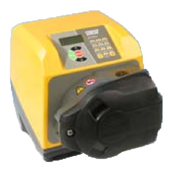
620DuN / 620Du pumps
Contents
1
2
3
4
5
6
7
8
8.1
8.2
9
9.1
9.2
3
3
3
4
5
6
8
12
13
15
16
17
17
19
20
20
22
22
23
23
23
24
24
25
25
25
27
28
31
32
33
34
35
36
36
36
22.12 Outputs 1, 2, 3, 4
37
38
38
38
39
40
40
42
43
44
44
45
45
46
46
47
47
48
49
50
50
52
53
54
54
55
55
56
59
60
61
61
62
62
63
63
63
64
1
Advertisement
Table of Contents

Related Manuals for Watson-Marlow 620DuN


Summary of Contents for Watson-Marlow 620DuN
-
Page 1: Table Of Contents
22.8 Direction input 18.2.1 Input 1: speed 22.9 Auto / manual toggle 18.2.2 Scaling - stroke input 18.2.3 Trim 22.10 MemoDose input 18.2.4 Exit 22.11 Leak detection input 18.3 Display 22.12 Outputs 1, 2, 3, 4 Watson-Marlow 620DuN and 620Du User Manual... - Page 2 35 Pumping accessories general operation 36 Trademarks 29.6 620RE and 620RE4 37 Warning not to use pumps in tube element loading patient-connected applications 111 29.7 620R continuous 38 Publication history tube loading 39 Decontamination certificate Watson-Marlow 620DuN and 620Du User Manual...
-
Page 3: Declaration Of Conformity
Watson-Marlow shall not be liable for any loss, damage, or expense directly or indi- rectly related to or arising out of the use of its products, including damage or injury... -
Page 4: When You Unpack Your Pump
Marlow, or a Watson-Marlow approved service centre. All repairs or modifications must have been made by Watson-Marlow Limited, or a Watson-Marlow approved service centre or with the express permission of Watson-Marlow. Warranties purporting to be on behalf of Watson-Marlow made by any person,... -
Page 5: Information For Returning Pumps
Equipment which has been contaminated with, or exposed to, body fluids, toxic chemicals or any other substance hazardous to health must be decontaminated before it is returned to Watson-Marlow or its distributor. A certificate included at the rear of these operating instructions, or signed state- ment, must be attached to the outside of the shipping carton. -
Page 6: Safety Notes
If the pump is used in a manner not specified by Watson-Marlow Limited, the protection provided by the pump may be impaired. Any person who is involved in the installation or periodic maintenance of this equip-... - Page 7 Do not fit any devices to the drive unit other than those tested and approved by Watson-Marlow. Doing so could lead to injury to persons or damage to property for which no liability can be accept- If hazardous fluids are to be pumped, safety procedures specific to the particular fluid and application must be put in place to protect against injury to persons.
-
Page 8: Pump Specifications
The pump can be digitally controlled with a contact closure or logic input signal. Analogue control The pump speed can be controlled through an analogue signal input in the ranges 0-10V, 1-5V or 4-20mA. Scaling can be controlled similarly using Analogue signal input 2. Watson-Marlow 620DuN and 620Du User Manual... - Page 9 (enclosure) undamaged by the contact in harmful quantities formation of ice on the (splashing over) enclosure. (Resist corrosion: 200-hour salt spray) * 620 cased pumps are rated to NEMA 4X (indoor use) only. Watson-Marlow 620DuN and 620Du User Manual...
- Page 10 80% up to 31C, 88F, decreasing (620Du) linearly to 50% at 40C, 104F Humidity (condensing) (620DuN) 10% - 100% RH Weight See table on previous page Noise <70dB(A) at 1m * Protect from prolonged UV exposure. Watson-Marlow 620DuN and 620Du User Manual...
- Page 11 BS EN 809 UL 61010A-1 CAN/CSA-C22.2 No 61010-1 Other Conducted emissions FCC 47CFR, Part 15.107 standards Radiated emissions FCC 47CFR, Part 15 NEMA 4X to NEMA 250 (indoor use) for IP66 products only Watson-Marlow 620DuN and 620Du User Manual...
-
Page 12: Pressure Capability
A warning is displayed when the user sets the speed above 165rpm. Note: Applies to 620RE MarkII and 620RE4 MarkII pumpheads only. (The 620LG is not limited). The pump’s software records the duration of operation above 165rpm. 0-2 bar pressure pumping Watson-Marlow 620DuN and 620Du User Manual... -
Page 13: Dimensions
+ 620R, 620RE + 620RE4 + 620L, 620LG IP31 16.5kg, 36lb 6oz 19.6kg, 43lb 3oz 20.1kg, 44lb 5oz 24.3kg, 53lb 9oz IP66 NEMA 4X 17.4kg, 38lb 6oz 20.5kg, 45lb 3oz 21.0kg, 46lb 5oz 25.2kg, 55lb 9oz Watson-Marlow 620DuN and 620Du User Manual... -
Page 14: Good Pump Installation Practice
However, to maintain performance at pressures above 2 bar, avoid running the pumphead below 50rpm. If low-flow, high-pressure operation is necessary, switching to a smaller tube is recommended. Watson-Marlow 620DuN and 620Du User Manual... -
Page 15: Do's And Do Not's
Tube selection: The chemical compatibility lists published in Watson-Marlow pub- lications are guides. If in doubt about the compatibility of a tube material and the duty fluid, request a Watson-Marlow tube sample card for immersion trials. Watson-Marlow 620DuN and 620Du User Manual... -
Page 16: Connecting This Product To A Power Supply
See 22.1 620N module removal and replacement. If the mains power cable is inappropriate for your installation, it can be changed. DuN, Du Please contact your local Watson-Marlow Bredel service centre. Watson-Marlow 620DuN and 620Du User Manual... -
Page 17: Start-Up Check List
The pump displays a language menu. Use the UP and DOWN keys to select your language. Press the ENTER key to confirm your choice. The information which follows assumes that your choice was English. Watson-Marlow 620DuN and 620Du User Manual... - Page 18 (Language can be reset as described later. See 18.19 Language.) The pump displays the Watson-Marlow start-up screen for four seconds, followed by the pump model identity screen for four seconds, and then the manual mode main screen.
-
Page 19: Switching The Pump On In Subsequent Power Cycles (If Not In Auto-Restart Mode)
If a fault is found, an error message is displayed. See 26.1 Error codes. The pump displays the Watson-Marlow start-up screen for four seconds followed by the pump model identity screen for four seconds, and then the manual mode main screen. -
Page 20: Manual Operation
Note: Priming can be achieved by pressing MAX (SHIFT, 4) until fluid flows through the pump and reaches the point of discharge, and then releasing MAX (SHIFT, 4). Watson-Marlow 620DuN and 620Du User Manual... - Page 21 . (decimal point, period) ( SHIFT, 0): used in numeric expressions as a decimal point. To enter 5.3, press 5, SHIFT, 0, 3. (Some languages use , (comma) to represent a decimal point. This pump uses .) Watson-Marlow 620DuN and 620Du User Manual...
-
Page 22: Speed
To toggle the pump’s rotation sense: Press DIRECTION (SHIFT, 1) to toggle the pump between clockwise and counter-clockwise rotation. Note: Direction control is available subject to access not being limited by security code. See 18.22 Security code. Watson-Marlow 620DuN and 620Du User Manual... -
Page 23: Keypad Lock
7 to pin 19, lower D-connector, to be able to start the pump from the keypad. See 22.7 Run/stop input. If STOP is pressed the remote run/stop switch will have no effect. You cannot invert the polarity of the remote direction signal. Watson-Marlow 620DuN and 620Du User Manual... -
Page 24: Backlight
To turn the auto-restart facility off: Turn off the mains power switch at the rear of the pump. Depress the STOP key while switching on the mains power switch at the rear of the pump. Watson-Marlow 620DuN and 620Du User Manual... -
Page 25: Main Menu
Trim, Analogue, Display, Pump I/D, Baud, Stop bits, Xon/Xoff, Flow units, Run time, Outputs, Remote stop, Auto-restart, Set max speed, Set min speed, Scrolling, Date/time, Backlight, ROM, Language, Defaults, Beep, Security code and Exit. Watson-Marlow 620DuN and 620Du User Manual... - Page 26 The MemoDose facility is used to remember the number of revolutions needed to dispense a previously dispensed volume of fluid, and cause the pump to dispense that volume repeatedly. Exit If Exit is selected, the pump returns to its last manual state with the pump stopped. Watson-Marlow 620DuN and 620Du User Manual...
-
Page 27: Pin-Secure Process Protection
If the main code is lost or forgotten: The Setup main security code can be bypassed by entering a special key sequence; all codes can then be cancelled and reset. Contact Watson-Marlow or your distributor for details. Watson-Marlow 620DuN and 620Du User Manual... -
Page 28: Head And Tubing Calibration
Head and tube; Tube; and Calibration dose. If Change is selected with no security code in place, the three options are displayed immediately. Use the UP and DOWN keys to make a selection. Press ENTER to confirm. Watson-Marlow 620DuN and 620Du User Manual... - Page 29 If Tube is selected or a pumphead choice has just been made, the pump dis- plays a list of standard tube sizes that can be used in the pumphead previously identified. Use the UP and DOWN keys to make a selection. Press ENTER to confirm. Watson-Marlow 620DuN and 620Du User Manual...
- Page 30 4 minutes. You may stop the calibration dose at any time with the STOP key - but allow the pump to run as long as possible to obtain the most accurate calibration. A minimum of 15 seconds is recommended. Watson-Marlow 620DuN and 620Du User Manual...
-
Page 31: Setup
Follow the reverse procedure using the UP key to move to an item on a previous screen of the menu. Make a selection using the UP or DOWN keys and press ENTER to confirm your choice. Watson-Marlow 620DuN and 620Du User Manual... -
Page 32: Trim
18.1 Trim Watson-Marlow 620DuN and 620Du User Manual... -
Page 33: Analogue
Select Analogue from the Setup menu using the UP or DOWN keys and press ENTER to confirm your choice. Four options are displayed: Input 1 - speed, Scaling - stroke, Trim and Exit. Watson-Marlow 620DuN and 620Du User Manual... -
Page 34: Input 1: Speed
The user is returned to the Analogue setup dis- play. Example figures are shown here. Alternatively the user can select Program to configure the pump to respond in a user-programmed way to any process signal range within 4-20mA, 0-10V or 1-5V. Watson-Marlow 620DuN and 620Du User Manual... -
Page 35: Scaling - Stroke
If 4-20mA, 0-10V or 1-5V is selected, the pump configures the hardware and calibration data appropriately. A confirmation screen is displayed briefly and the user is returned to the Analogue setup menu. If Program is selected, the pump offers: mA (4-20mA) and V (0-10V). Use Watson-Marlow 620DuN and 620Du User Manual... -
Page 36: Trim
The pump can display three default screens in manual mode: revolutions per minute, flowrate in a choice of units, or both. In the first screen of the Setup menu select Display using the UP and DOWN Watson-Marlow 620DuN and 620Du User Manual... -
Page 37: Pump I/D
Use the numeric keys to enter a new number in the display and press ENTER to confirm your decision. An example is shown here. The pump displays the first screen of the Setup menu. Watson-Marlow 620DuN and 620Du User Manual... -
Page 38: Baud
The pump displays a screen allowing you to set flow control on or off. Use the UP and DOWN keys to choose and press ENTER to confirm your decision. The pump displays the second screen of the Setup menu. Watson-Marlow 620DuN and 620Du User Manual... -
Page 39: Flow Units
0.01 and 15.00. Press ENTER to confirm your decision. Press STOP if you decide to make a different choice of units. A confirmation screen appears briefly and the pump displays the second screen of the Setup menu. Watson-Marlow 620DuN and 620Du User Manual... -
Page 40: Run Time
Provides a status output to indicate whether the pump is in analogue control mode or manual control mode. General alarm Provides an alarm output when any system error condition occurs except: leak detected; analogue signal out of range; analogue over-signal; analogue no sig- nal. Watson-Marlow 620DuN and 620Du User Manual... - Page 41 Output 3 and output 4 provide open collector logic outputs from pins 13 and 12, upper D-connector, respectively. A supply voltage from the pump (5V, 10V, 12V) or user-supplied up to 30V to pin 22, upper D-connector, provides the voltage level for these logic status outputs. DuN, Du Watson-Marlow 620DuN and 620Du User Manual...
-
Page 42: Remote Stop
If No is chosen, the pump asks the user to make a further choice, according to whether the pump is required to run on an open or closed remote switch: Open=stop or Open=run. Choose using the UP and DOWN keys and press Watson-Marlow 620DuN and 620Du User Manual... -
Page 43: Auto-Restart
If On is chosen, the pump returns the user to the fourth screen of the Setup menu, where an exclamation mark ( ! ) is now visible. This mark confirms that the auto-restart feature is in place and will operate the next time power is lost and restored. Watson-Marlow 620DuN and 620Du User Manual... -
Page 44: Set Maximum Allowed Speed
The minimum allowed speed of the drive defaults to 0.1rpm. It is possible to set this limit at any speed up to 264rpm, as long as the maximum speed is at least 1rpm greater. In the fourth screen of the Setup menu select Set min speed using the UP Watson-Marlow 620DuN and 620Du User Manual... -
Page 45: Scrolling
The pump’s real-time clock can be set with the date and time. In the fifth screen of the Setup menu select Date/time using the UP and DOWN keys. Press ENTER to confirm your choice. The pump displays any pre- Watson-Marlow 620DuN and 620Du User Manual... -
Page 46: Backlight
CHK 123, for example. This may be required if reporting pump performance to the Watson-Marlow service department. Alternatively ... Press 1 (DIRECTION) and DOWN together to interrupt the display and show the pump’s ROM version for four seconds. Watson-Marlow 620DuN and 620Du User Manual... -
Page 47: Language
Press ENTER to confirm your decision. If Yes was chosen, the pump resets its factory defaults and redisplays the sixth Setup screen. If No was cho- sen, the pump makes no changes to its setup and redisplays the sixth Setup screen. Watson-Marlow 620DuN and 620Du User Manual... -
Page 48: Beep
To toggle the sound on and off, stop the pump. Turn off the mains power switch at the rear of the pump. Depress the UP and 1 (DIRECTION) keys while switching on the mains power switch at the rear of the pump. Watson-Marlow 620DuN and 620Du User Manual... -
Page 49: Security Code
If the codes tally and, for a user code, if there is no clash with a previously set Watson-Marlow 620DuN and 620Du User Manual... -
Page 50: Exit
Note: If a code has been set but forgotten, it is still possible to access the Setup screens to cancel the code or reset it to another three-digit number. Contact your supplier or Watson-Marlow Technical support for the bypass sequence. 18.23 Exit In the seventh screen of the Setup menu Exit is highlighted. - Page 51 Cycle through the Pin out menu screens until the fifth screen is displayed. Select Exit using the UP or DOWN keys and press ENTER to confirm your choice. Alternatively ... Repeatedly press STOP to go back level by level until the main menu is displayed. Watson-Marlow 620DuN and 620Du User Manual...
-
Page 52: Memodose
OR ... 3 Press the STOP key. The pump stops. Press the MENU (SHIFT, 7) key. Use the UP or DOWN keys to select MemoDose. Press ENTER to confirm. The pump displays the MemoDose screen. Watson-Marlow 620DuN and 620Du User Manual... -
Page 53: Changing Dosing Speed
Note: To retain the MemoDose value through a power interruption the pump must be in auto-restart mode. The dosing cycle will resume at the start of a dose and wait for START to be pressed, with the MemoDose percentage screen displayed. See 18.12 Auto-restart. Watson-Marlow 620DuN and 620Du User Manual... -
Page 54: Footswitch Operation And Other Remote Inputs And Outputs With Memodose
MemoDose if previously enabled; it can also be enabled while in MemoDose mode. See 14.4 Keypad lock. 21 Exit DuN, Du Press Exit in the Main menu to return to the Manual mode main screen. Watson-Marlow 620DuN and 620Du User Manual... -
Page 55: Automatic Control Wiring Using The 620N Module
If necessary, remove the module’s earth link from the back of the drive. However, the link is long enough to allow the module to fold back to give access to the circuit board inside and to the back of the drive. Watson-Marlow 620DuN and 620Du User Manual... -
Page 56: Wiring Up
9.5mm-5mm. The cable section must be circular to ensure a seal. The recommended cable and cable glands must be used for the IP66 (NEMA 4X) version of this pump; otherwise ingress protection may be jeopardised. Watson-Marlow 620DuN and 620Du User Manual... - Page 57 Strip the outer sheath as necessary and remove 5mm of insulation from the conductors. No tinning or ferrule is required. Note: If very stiff or large-diame- ter cable is used, it may be convenient to strip the outer sheath before passing Watson-Marlow 620DuN and 620Du User Manual...
- Page 58 Permanent damage, not covered by warranty, may result. The maximum rating on the relay contacts of this pump is 30V DC; maximum load 30W. Note: Also suitable for low power: ie, 1mA at 5VDC minimum. Watson-Marlow 620DuN and 620Du User Manual...
-
Page 59: Speed: Analogue Input
The pump will provide an increasing flow rate for a rising control signal (non-inverted response) or an increasing flow rate for a falling control sig- nal (inverted response). See 18.2 Analogue. Watson-Marlow 620DuN and 620Du User Manual... -
Page 60: Scaling: Analogue Input
This is done in software - see 18.1 Trim in the Setup section. When using a remote potentiometer, it is important to set the analogue input to volt- Watson-Marlow 620DuN and 620Du User Manual... -
Page 61: Speed: Analogue Output
The pulse train from the pump can be used to calculate the speed of rotation or to determine the number of pumphead revolutions. This output has the required strength to be effective up to 3m from the pump. Longer cable runs require signal amplification. Watson-Marlow 620DuN and 620Du User Manual... -
Page 62: Run/Stop Input
Alternatively a logic signal may be applied to the i/p terminal and the 0V terminal of the Direction i/p connector (J2). Low input for clockwise rotation, high input for counter-clockwise rotation. With no connection the pump defaults to clockwise rotation. Watson-Marlow 620DuN and 620Du User Manual... -
Page 63: Auto / Manual Toggle Input
Alternatively a logic input may be applied to the i/p ter- minal, ground to the 0V terminal. High input indicates a leak. Connect the cable of a Watson-Marlow Tube monitor leak detector as follows: Tube monitor wire colour 620N module... -
Page 64: Outputs
An appropriate voltage supply is available where required on each connector. In addition, supplies may be drawn from the Spare supplies connector (J12). In the table below, “Max load” is the maximum total load on each supply, irrespec- tive of the number of connections. Watson-Marlow 620DuN and 620Du User Manual... -
Page 65: Rs485 Input
A to A, B to B, screen to 0V. Ensure that the pump is configured to operate under Network control. More than one pump may be controlled with the same RS485 signal: con- nect all pumps in parallel. See 25 Network control and oper- ation. Watson-Marlow 620DuN and 620Du User Manual... - Page 66 0V and 5V; but in practice <0.4V (<16mA) and 2.4-5V (<0.4mA). They are not suitable for driving relays. If a relay is to be driven by the TTL signal, it must be done as described under Logic output 1-4, below. Watson-Marlow 620DuN and 620Du User Manual...
- Page 67 059.3122.000, up to a maximum of 16 pumps. If a connection must be made to a pc fitted with a 25-pin serial outlet, use RS232 network adaptor 059.3123.000, shown, dotted, left, instead of 059.3121.000. Watson-Marlow 620DuN and 620Du User Manual...
-
Page 68: Speed: Analogue Input 1
16. The pump will provide an increasing flow rate for a rising control signal (non-inverted response) or an increasing flow rate for a falling control signal (invert- ed response). See 18.2 Analogue in the Setup menu. Watson-Marlow 620DuN and 620Du User Manual... -
Page 69: Scaling: Analogue Input 2
When using a remote potentiometer, it is important to set the analogue input to volt- age in the Setup menu. Otherwise the reference voltage supply from pin 21 will be overloaded and will not provide a full 5V or 10V. Watson-Marlow 620DuN and 620Du User Manual... -
Page 70: Tachometer Frequency Output
This output has the required strength to be effective up to 3m from the pump. Longer cable runs require signal amplification. Watson-Marlow 620DuN and 620Du User Manual... -
Page 71: Direction Input
18.11 Remote stop in the Setup menu. 23.6 Direction input To enable remote direction control and disable the DIRECTION (SHIFT, 1) key on the keypad, link pins 6 and 18 of the lower D-connector. Connect a remote switch Watson-Marlow 620DuN and 620Du User Manual... -
Page 72: Memodose Input
5V to 24V logic as shown above, using pin 8 as the input and pin 20 as the 0V (lower D-connector). Note: This input is software-debounced, so the signal can be either momentary or maintained during the dose. If maintained, the signal must be removed before the next dose. Watson-Marlow 620DuN and 620Du User Manual... -
Page 73: Leak Detection Input
Closed circuit indicates a leak. Alternatively a logic input may be applied to pin 2 of the upper D-connector, ground to pin 15. High input indicates a leak. Connect a Watson-Marlow leak detector in the same way, drawing 12V to power it from pin 21 of the upper D-connector. -
Page 74: Pump Status Outputs
Output 1. Do not connect to any device requiring more than 1 TTL load. By default, output 1 is configured to indicate Run/Stop status. See 12 Switching the pump on for the first time. Watson-Marlow 620DuN and 620Du User Manual... -
Page 75: Logic Output 2
Output 2. Do not connect to any device requiring more than 1 TTL load. By default, output 2 is configured to indicate Direction status. See 12 Switching the pump on for the first time. Watson-Marlow 620DuN and 620Du User Manual... -
Page 76: Logic Output 3
Output 4. Do not connect to any device requiring more than 50mA. By default, output 4 is configured to indicate General alarm status. See 12 Switching the pump on for the first time. Watson-Marlow 620DuN and 620Du User Manual... -
Page 77: Supply Voltages
Voltage supply for the 620N wash- +22.5V down module. Do not use Reference voltage for remote poten- +10V tiometer speed control. Do not use as a general supply voltage Note: All DC supplies are stabilised except the +22.5V. Watson-Marlow 620DuN and 620Du User Manual... -
Page 78: Automatic Control And Operation
The pump displays whichever of six auto running screens is appropriate accord- ing to the previously selected auto mode - 4-20mA, 1-5V or 0-10V with or without scaling in place. The auto running screens display four pieces of information: the speed at which Watson-Marlow 620DuN and 620Du User Manual... - Page 79 If keypad lock was not in place when STOP was pressed, the interruption screen offers a choice: Continue to continue auto operation, or Manual to switch to manual mode. Use the UP and DOWN keys to choose and press ENTER to confirm. Watson-Marlow 620DuN and 620Du User Manual...
-
Page 80: Network Control And Operation
The only keys active are STOP, MAN (SHIFT, 6) and MENU (SHIFT, Remote stop, auto/man, dose, direction enable and direction inputs are inac- tive. Leak input is active. See 26.1 Error codes. All pump status outputs are active. Watson-Marlow 620DuN and 620Du User Manual... - Page 81 Manual to set the pump to manual control (see 14 Manual operation), or Menu to display the main menu (see 15 Main menu). Use the UP and DOWN keys to choose and press ENTER to confirm. Watson-Marlow 620DuN and 620Du User Manual...
-
Page 82: Rs232 And Rs485 Command Strings
Note 4: ‘n’ can be any number from 1 to 16 inclusive (1 to 32, 620DuN), and by exception the # symbol can be used as an all-drives command; but not with the RS, RT or ZY commands, as the results would be indeterminate. Watson-Marlow 620DuN and 620Du User Manual... -
Page 83: Troubleshooting
Check for any kinks or blockages in the lines. Check that any valves in the lines are open. Check that the correct wall-thickness tube is being used. Check direction of rotation. Check that the rotor is not slipping on the drive shaft. Watson-Marlow 620DuN and 620Du User Manual... -
Page 84: Error Codes
Turn OFF. Check network and connections. Or seek support detected RS485/RS232 Turn OFF. Check network and connections. Or seek support fault RS485/RS232 lost Turn OFF. Check network and connections. Or seek support General error Turn OFF. Seek support condition Watson-Marlow 620DuN and 620Du User Manual... -
Page 85: Drive Maintenance
27 Drive maintenance DuN, Du There are no user serviceable parts inside the pump. The unit should be returned to Watson-Marlow or its appointed agents or distributors for service. 28 Drive spares DuN, Du Replaceable main fuse, type T5A H 250V: FS0043... -
Page 86: Re, 620Re4 And 620R Key Safety Information
The electrical guard switch on cased pumps should never be used as primary protection. Always disconnect the mains power supply to the pump before opening the pumphead guard. Watson-Marlow 620DuN and 620Du User Manual... -
Page 87: Re, 620Re4 And 620R Pumping Conditions
Waste pipe work should run to a suitable container or drain. The leak detector installation procedure is included in the leak detector kit. If unsure of an installation please contact your local Technical Support Office. Watson-Marlow 620DuN and 620Du User Manual... -
Page 88: Re, 620Re4 And 620R General Operation
Ensure that the rollers are engaged and locked out against the tubing Close the guard and push it against the track until the latch engages. Connect suitable pipe work to the pumphead using the appropriate connectors for the tube element. See below. Watson-Marlow 620DuN and 620Du User Manual... -
Page 89: Re And 620Re4 Tube Element Loading
Always isolate the pump from the mains power supply before opening the guard or performing any positioning, removal or maintenance. 620RE element pumpheads are factory set to accept Watson-Marlow LoadSure tube elements. Pumping performance will be adversely affected if LoadSure elements are not used. -
Page 90: R Continuous Tube Loading
Always isolate the pump from the mains power supply before opening the guard or performing any positioning, removal or maintenance. 620R continuous tubing pumpheads are factory set to accept Watson-Marlow 600 series 3.2mm wall tubing. Pumping performance will be adversely affected if Watson-Marlow tubing is not used. -
Page 91: Continuous Tube Removal
If fluid is spilled inside the pumphead, flush the pumphead out with water and mild detergent as soon as possible. If specific cleaning agents are required to clean the spillage, please consult Watson-Marlow Technical Support Office before proceeding, in order to confirm chemical compatibility. - Page 92 After removing the rotor and track, it is advisable to remove the metal key from the keyway, clean and reassamble. The key fits its keyway tightly. It may be freed by tapping gently with a screwdriver or other suitable tool. Watson-Marlow 620DuN and 620Du User Manual...
- Page 93 When closing the guard, check it does not make contact with the rotor. If it does, the rotor has been fitted incorrectly. Re-open the guard, remove and refit the rotor, and close the guard. Watson-Marlow 620DuN and 620Du User Manual...
-
Page 94: Re, 620Re4 And 620R Cip And Sip
Ensure that controlled waste pipework is fitted to allow a safe release of steam in the event of a tube failure. Ensure a 1m safety zone is maintained around the pumphead during SIP cycles. Watson-Marlow 620DuN and 620Du User Manual... -
Page 95: Re, 620Re4 And 620R Pumphead Spares
Ensure that the pumphead door is closed and locked before SIP cleaning commences. 29.11 620RE, 620RE4 and 620R pumphead spares Watson-Marlow 620DuN and 620Du User Manual... - Page 96 Adaptor - Bodine (white polypropylene ring) FN0488 Cased drive track locating screws M6x10 FN0523 Close-coupled track locating screws M6x20 FN0581 Rotor locating washer M6 MR2251B Rotor locating bolt M6 x 25 TT0006 5mm Allen key MA0017 Magnet Watson-Marlow 620DuN and 620Du User Manual...
-
Page 97: Re, 620Re4 And 620R Performance Data
Note: Flow rates quoted have been rounded for simplicity, but are accurate to with- in 5% - well within the normal tubing tolerance variation of flow rate. They should therefore be taken as a guide. Real flow rates in any application must be determined empirically. Watson-Marlow 620DuN and 620Du User Manual... -
Page 98: Re, 620Re4 And 620R Flow Rates
620RE4 (hard) (hard) Speed 12.0 17.0 12.0 17.0 0.004 0.01 0.003 0.004 620 Pumpsil silicone, l/min 620R 620RE 620RE4 Speed 12.7 15.9 12.0 17.0 12.0 17.0 0.001 0.003 0.004 0.01 0.004 0.01 0.003 0.004 Watson-Marlow 620DuN and 620Du User Manual... - Page 99 620RE4 (hard) (hard) Speed 12.0 17.0 12.0 17.0 0.001 0.002 0.001 0.001 620 Pumpsil silicone, USGPM 620R 620RE 620RE4 Speed 12.7 15.9 12.0 17.0 12.0 17.0 0.0003 0.001 0.001 0.001 0.001 0.002 0.001 0.001 Watson-Marlow 620DuN and 620Du User Manual...
- Page 100 15.9 902.0159.032 903.0159.032 913.0159.032 inch Sta-Pure Neoprene 960.0064.032 920.0064.032 950.0064.032 960.0096.032 920.0096.032 950.0096.032 12.7 960.0127.032 920.0127.032 950.0127.032 15.9 960.0159.032 920.0159.032 950.0159.032 inch Fluorel Chem-Sure 970.0064.032 965.0064.032 970.0096.032 965.0096.032 12.7 970.0127.032 965.0127.032 15.9 970.0159.032 965.0159.032 Watson-Marlow 620DuN and 620Du User Manual...
- Page 101 960.0120.PFT 960.0170.PFT Chem-Sure 965.0120.SST 965.0170.SST Bioprene TM 903.P120.PFT 903.P170.PFT Bioprene TL 903.0120.PFT 903.0170.PFT Pumpsil 913.0120.PFT 913.0170.PFT silicone Marprene TM 902.P120.PPC 902.P170.PPC Marprene TL 902.0120.PPC 902.0170.PPC Neoprene 920.0120.PPC 920.0170.PPC Note: = for 4 bar use Watson-Marlow 620DuN and 620Du User Manual...
-
Page 102: L And 620Lg Pumpheads
The electrical guard switch on cased pumps should never be used as primary protection. Always disconnect the mains power supply to the pump before opening the pumphead. Watson-Marlow 620DuN and 620Du User Manual... -
Page 103: L And 620Lg Pumping Conditions
A 620 pump supplied with a 620L pumphead is not intended for use with any other pumphead. However, the pumphead can be removed for cleaning or maintenance. Always isolate the pump from the mains power supply before opening the guard or performing any positioning, removal or maintenance. Watson-Marlow 620DuN and 620Du User Manual... - Page 104 Clean and grease the projecting dog of the drive shaft. Position the cleaned pumphead so that it engages with the drive-shaft dog. Use two M6 screws to secure the pumphead to the adaptor plate. Reverse the directions above to reposition the track. Watson-Marlow 620DuN and 620Du User Manual...
-
Page 105: L And 620Lg Tube Loading
Unscrew and remove the 625L inlet clamping peg. Connect the twin inlet tubes and outlet tube using the appropriate Y-piece connector and clips. Fit the inlet tubes into the correct size clamping block. Locate the Y-piece end of the ele- Watson-Marlow 620DuN and 620Du User Manual... -
Page 106: L And 620Lg Care And Maintenance
However, the pump warranty will be invalidated if this is done. The factory setting is 20.3mm vertically from the rotor side of the sprung track to the top of the track cover. Watson-Marlow 620DuN and 620Du User Manual... -
Page 107: L And 620Lg Pumphead Spares
Tube clamp set MR3017S Adaptor plate MRA0144A Tube locating peg FN0493 M6x12 screws x 6 MRA0150A Rotor assembly BB0018 Shaft bearing MR0850S Front plate TT0005 10mm / 3/8in spanner MRA3020A Track assembly MR3002 Foot Watson-Marlow 620DuN and 620Du User Manual... -
Page 108: L And 620Lg Performance Data
620L, Sta-Pure, ChemSure, l/min 620L, Sta-Pure, ChemSure, USGPM Speed Tube bore (4.0mm wall) Speed Tube bore (4.0mm wall) 8.0mm 12.0mm 16.0mm 8.0mm 12.0mm 16.0mm 0.002 0.003 0.005 0.0005 0.0009 0.0012 0.81 1.52 2.05 12.4 1.39 2.38 3.28 Watson-Marlow 620DuN and 620Du User Manual... -
Page 109: L Tubing Codes
0.01672 913.A120.040 Continuous 12.0mm 0.03214 913.A160.040 16.0mm 0.04353 Neoprene Dispensing information Bore Litres/rev 920.E080.K40 8.0mm 0.01721 Y element 920.E120.K40 12.0mm 0.02901 920.E160.040 16.0mm 0.05004 920.0080.040 8.0mm 0.01721 920.0120.040 Continuous 12.0mm 0.02901 920.0160.040 16.0mm 0.05004 Watson-Marlow 620DuN and 620Du User Manual... -
Page 110: Lg Element Codes
All models for use with 624AFN filling needles Tube monitor with 25-pin D-connector 059.4501.520 620U, 620Du, 620Di Tube monitor, bare lead 059.450N.520 620UN, 620DuN, 620DiN 620AL Leak detector kit, bare lead 069.7131.000 620UN, 620DuN, 620DiN Watson-Marlow 620DuN and 620Du User Manual... -
Page 111: Trademarks
36 Trademarks DuN, Du Watson-Marlow, Bioprene, Pumpsil and Marprene are trademarks of Watson-Marlow Limited. Tygon is a trademark of the Saint Gobain Performance Plastics Company. Fluorel is a trademark of 3M. Sta-Pure and Chem-Sure are trademarks of W.L.Gore and Associates. -
Page 112: Decontamination Certificate
In compliance with the UK Health and Safety at Work Act and the Control of Substances Hazardous to Health Regulations, you are required to declare the sub- stances which have been in contact with product(s) you return to Watson-Marlow or its subsidiaries or distributors. Failure to do so will cause delays. Please ensure that you fax us this form and receive an RGA (Returned Goods Authorisation) before you despatch the product(s).
Need help?
Do you have a question about the 620DuN and is the answer not in the manual?
Questions and answers