Table of Contents
Advertisement
Quick Links
Advertisement
Table of Contents

Related Manuals for Watson-Marlow 825


Summary of Contents for Watson-Marlow 825
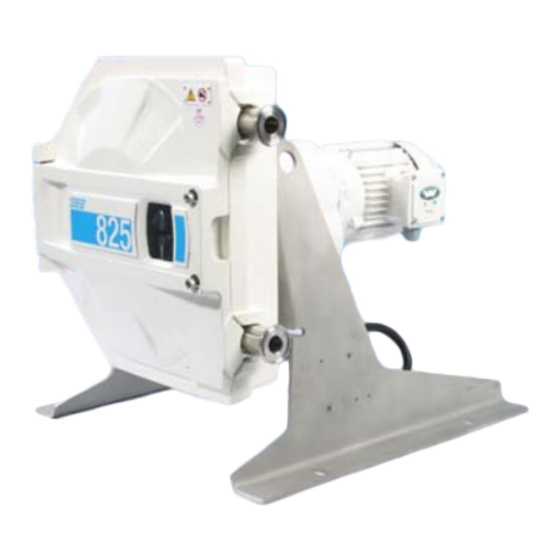
- Page 1 INSTRUCTIONS FOR USE Machine Designation, Model variant of a: 825 Pump or Pumphead 840 Pump or Pumphead Date of publication: 12 of September 2024 Version of publication: PB0190 v5.02 ORIGINAL INSTRUCTIONS COMPLIANCE NOTES T OGGLE Page 1...
-
Page 2: Preface
Preface Disclaimer The information contained in this document is believed to be correct, but Watson-Marlow accepts no liability for any errors it contains and reserves the right to alter specifications without notice. If the product is used in a manner which has not been specified in these instructions, then the protection provided by the equipment may be impaired. -
Page 3: Table Of Contents
Table of Contents Preface ..........................2 Disclaimer ........................... 2 Translation of the original instructions ................. 2 Introduction: Document ....................6 Information types ........................6 Trademarks ..........................7 Terminology ..........................7 Abbreviations ..........................7 Introduction: Product ..................... 8 General description ........................8 Intended use .......................... - Page 4 Removing product from original packaging ............... 31 Unpacking, inspection and packaging disposal ..............31 Installation: Chapter 1 (Physical) ................33 Part 1: Physical installation requirements ................33 8.1.1 Intended mounting (Frame Support) ................33 8.1.2 Intended environment ....................33 8.1.3 Area around the product ....................
- Page 5 14.3 Pumphead maintenance ......................57 14.3.1 Tubing ........................... 57 14.3.2 Roller adjustment ......................64 Troubleshooting ......................65 15.1 Troubleshooting ........................65 15.1.1 Troubleshooting table ..................... 65 15.2 Technical support ........................66 15.2.1 Manufacturer ........................66 15.3 Warranty ..........................67 15.3.1 Conditions ........................... 67 15.3.2 Exceptions ...........................
-
Page 6: Introduction: Document
Introduction: Document These instructions are the installation and maintenance instructions, for a Watson-Marlow 800 series pumphead or pump, for reference by a: Responsible Person Individual responsible for the installation, maintenance, and safe use of the product by operators. These instructions do not contain any operator instructions; The product is a partially complete... -
Page 7: Trademarks
The following terminology is used in these instructions: This terminology is explained further when first relevant Standard Product An 825 or 840 pumphead and support frame, which is identical each time, manufactured by Watson-Marlow. Engineered Product An 825 or 840 pumphead, support frame, and attached... -
Page 8: Introduction: Product
Introduction: Product General description A Watson-Marlow 800 Series pump provides a flowrate of fluid positive displacement through a tube element and fluid path. A general illustration is provided below. Exact arrangement will vary by model (Engineered Product is shown): Drive... -
Page 9: Intended Use
Intended use All model variants of the 800 series pumps are designed for the controlled movement of fluid, in ordinary safe locations, except those fluids or applications listed below as prohibited use. Prohibited use: In patient-connected applications In an environment that requires explosion proof certification ... -
Page 10: Safety
COMPLIANCE NOTES T OGGLE 3.1.1 Instructions for renewing safety symbols If product safety symbols suffer damage, contact your local Watson-Marlow representative for information on obtaining replacements. Safety devices The pumphead features a proximity sensor, which when connected to a control system can function as an emergency stop in safety applications up to category 1, SIL 1 as defined by ISO 13849-1, IEC 62061. -
Page 11: Safety Signals
COMPLIANCE NOTES T OGGLE Safety signals Signals indicate a possible hazard. COMPLIANCE NOTES T OGGLE 3.3.1 Signals: With risk of personal injury Signals indicating risk of a personal injury are presented when relevant to a task in this format: WARNING The WARNING signal word indicates a hazard. -
Page 12: Personal Protective Equipment (Ppe)
Personal protective equipment (PPE) The following minimum PPE will be required during specific tasks: Safety glasses Safety boots Gloves chemically compatible with the chemicals being pumped A risk assessment by a responsible person must be undertaken to identify: Suitability of PPE for the application ... -
Page 13: Product Overview
825 or 840 pumphead with support frame support frame, and drive (motor mounted inverter model shown) Engineered products are bespoke products produced by Watson-Marlow. These NOTE products have custom features or specifications. Contact your Watson-Marlow representative to identify which features or specifications apply to your model For the pump to provide a flowrate, a tubing element must be installed. -
Page 14: Pumphead
4.1.1 Pumphead 4.1.1.1 Pumphead variations Pumphead model For flowrates up to: 2,060 L/Hr For flowrates up to: 8,140 L/Hr General arrangement of Pumphead Item Description Quantity Tube clamp Rocker assembly Rotor assembly Roller assembly Connector Door proximity sensor Tube element Locking pin assembly 4.1.1.2 Engineered Options... - Page 15 Place 1 x Bolt (1) through support frame into Pumphead, ensuring that 1 x Washer (2) and 1 x Washer (3) are fitted against the support frame. Repeat process for remaining attachment hole. Tighten Bolt (1) to 35.5Nm for 825 model and 61.3Nm for 840 model Support to pumphead fixtures Model Item...
- Page 16 4.1.1.4 Attaching a drive to pumphead Preparing drive and Pumphead: Before attaching a drive to the pumphead, ensure that it is of the correct specifications to allow the pumphead to operate correctly. Ensure the pumphead is on a flat horizontal surface allowing sufficient room around it to carry out the necessary maintenance activities Ensuring that all local lifting practices are adhered to and carried out by qualified personnel only.
- Page 17 2. At the back of the pumphead and drive, fit 1 x Washer (2), 1 x Washer (3) and 1 x Nut (4) on to Bolt (1). 3. Repeat process for remaining attachment holes. 4. Tighten nut (4) to 39Nm for 825 and 100Nm for 840 model Page 17...
- Page 18 4.1.1.5 Attaching a rotor to driveshaft Rotor to drive shaft attachment fixtures. Model Item Description Model Item Description 1 x Bolt M10 x 35 SKT 1 x Bolt M16 x 35 SKT 1 x Washer M10 s/Coil 1 x Washer M16 s/Coil 1 x Plate Washer M10 1 x Plate Washer M16 1x Shaft Collar...
- Page 19 Keep fingers clear from back of rotor to prevent crushing injuries or cuts 7. Fit large plate washer (3), spring washer (2) and bolt (1)into drive shaft. 8. Tighten securing bolt (1) to 20Nm for 825 model and 100Nm for 840 model. Page 19...
- Page 20 Fixtures supplied for attaching drive to Pumphead: Model Item Description Model Item Description 4 x Bolt M8 x 35 HEX HD 4 x Bolt M12 x 45 HEX HD 8 x Washer M8 S.S 8 x Washer M12 S.S 4 x Washer M8 s/COIL SP 4 x Washer M12 s/COIL SP 4 x Nut M8 HEX FULL GRA 4 x Nut M12 HEX FULL GRA...
- Page 21 4.1.1.6 Tubing Tubing is available in two materials: Bioprene Sta-Pure Pressure and temperature ratings: Model Descrip on Temperature Bioprene tubing element 2 Bar 5°C-80°C ( 41°F to 176°F) Bioprene tubing element 2.3m length 2 Bar 5°C-80°C ( 41°F to 176°F) Bioprene tubing element 3.5 Bar 5°C-80°C ( 41°F to 176°F)
-
Page 22: Drive
4.1.2 Drive 4.1.2.1 General arrangement of drive The general arrangement of the drive is provided below: An Engineered Product with motor mounted inverter is shown - the exact arrangement will depend on model. Figure number Description Gearbox Inverter Motor Motor nameplate Motor mounted inverter (optional) with local control (option) Motor mounted inverter: Remote Control/DIP Switches/LED Diagnostic Ports options... -
Page 23: Name Plate
Name plate 4.2.1 Product Nameplate is fixed to the pumphead. Manufacturer details Serial number 4.2.2 Drive (Engineered Product) 4.2.2.1 Motor The electric motor nameplate is fixed to its body. It will vary, dependent on the model. Example of a name plate shown below: Item Descrip on Item Descrip on... - Page 24 4.2.2.2 Motor mounted inverter (Optional) The inverter nameplate is fitted on top of the inverter. It will vary dependent on the inverter model. Example of a name plate shown below: Item Descrip on Manufacturers details Model/version details Opera ng and protec on specifica ons Conformity specifica ons Hazard warnings COMPLIANCE NOTES T OGGLE...
-
Page 25: Specification Summary
Specification summary This section provides a summary specification for the purposes of an overview. Detailed information is provided in Section 17 4.3.1 Performance 4.3.1.1 Flowrate The flowrate of the pump is a combination of pumphead speed, and application (pressure, fluid viscosity). -
Page 26: Dimensions
Dimension X is dependent on the size of drive selected (outlined in red). NOTE 4.3.3.1 Weight Nominal weight of Pumps 825 Series 840 Series 100 kg (220 lb ) 175 kg (385 lb) NOTE Weight depends upon the drive model fitted 4.3.3.2... -
Page 27: Electrical Power Specification (Ep)
Local/Remote Operation ✔ ✔ Local Control by HMI ✔ ✔ Please contact your Watson-Marlow representative to determine which features your pump has. 4.3.5.1 Control panel overview (EP: Local control models) A local control option can be fitted to some models. - Page 28 4.3.5.3 PROFIBUS DP Inverter Interface Option NORD Profibus SK CU4-PBR, Specifications: Version: Protocol: DPV0, DPV1 Baud Rate: Maximum 12 MB/s Profibus 2 digital Inputs LED: 2 Status and 2 Failure Page 28...
-
Page 29: Storage
Storage COMPLIANCE NOTES T OGGLE Storage conditions Storage of the pump and tube elements should be carried out in accordance with the following: Pump 1. Storage temperature range: -40 °C to 70 °C (-40 °F to 158 °F) 2. Indoors, cool, and dry 3. -
Page 30: Lifting And Carrying
Product is heavy. Suitable lifting aids are to be used to prevent crushing injuries or death. Ensure all lifting aids are in date for servicing. The correct PPE must be worn when carrying out lifting operations. Nominal Weights: 825; 100kg (187lb) 840; 175kg (385lb) Page 30... -
Page 31: Unpacking Your Pump
Components supplied with your pump 800 SERIES TOGGLE The following components are supplied with the pump/pumphead. 1. Allen Key ,10 mm for 840 or 6 mm for 825. 2. Tube Element, supplied fitted to pump. 3. Relevant manufactures manuals. Removing product from original packaging Procedure 1. -
Page 32: Installation
Installation Installation is provided in the following order. 1. Installation: Chapter 1 (Physical) 2. Installation: Chapter 2 (Electrical power) 3. Installation: Chapter 3 (Control system) 4. Installation: Chapter 4 (Fluid path) Follow the installation in the specific order above. to ensure that hazards are minimised. Each of the chapters, are divided into two main parts. -
Page 33: Installation: Chapter 1 (Physical)
Installation: Chapter 1 (Physical) Part 1: Physical installation requirements 8.1.1 Intended mounting (Frame Support) Model 490mm 81mm 64mm 300mm 272mm 184mm (19.29”) (3.91”) (2.52”) (11.81”) (10.71”) (7.24”) 730mm 118mm 90mm 380mm 450mm 239mm (28.74”) (4.65”) (3.54”) (14.96”) (17.72”) (9.41”) COMPLIANCE NOTES T OGGLE 8.1.2 Intended environment The product must be installed such that no part of the pump may exceed the environment limits... -
Page 34: Area Around The Product
The pump must always be accessible to facilitate the following Number Comment Suggested Distance Clearance for door to open fully during maintenance and 825: 500mm cleaning 840: 700mm Allow sufficient room for airflow and access for maintenance, cleaning, and programming Allow sufficient head room for access and airflow... -
Page 35: Surface Characteristics
8.1.4 Surface characteristics The pump must be installed as follows in accordance with the instructions below: Ensure that: Pump is on a flat horizontal surface CAUTION Pump must be on a flat horizontal surface to prevent it from tipping over and causing crushing injuries or cuts and abrasions. With a frame support suitable to: 1. -
Page 36: Part 2: Physical Installation
Part 2: Physical Installation 8.2.1 Pre-physical installation checklist Carry out the following pre-installation checklist prior to following the installation procedure below: Ensure all sections of Part 1 of the physical installation requirements have been met Ensure that M16 anchor bolts are available (use Grade 5.6 bolts as a minimum) ... -
Page 37: Installation: Chapter 2 (Electrical Power)
Drive units Pumphead, with support frames will require a drive unit with the following specification. Contact your Watson-Marlow representative for more information. 825 & 840 Series IE3 motors Integrated with Nord SK Inverter (5-50Hz) 230/400V 3ph IP55. (Example Model No.VIB/R) - Page 38 9.1.1.5 Cable (wiring) specification A power cable is not supplied with this product and Watson-Marlow are unable to give a recommendation on the supply cable size. The electrical installer should be consulted for the correct cable size to be used. The supply cable should be suitable for the operating environment, power supply and geographical legislation.
-
Page 39: Part 2: Electrical Power Installation
Part 2: Electrical power installation 9.2.1 Pre-electrical power installation requirement checklist Prior to electrical power installation, carry out the following pre-installation checks to ensure that. The pump has been physically installed in accordance with section 8 The pump has a suitable drive unit installed (section 9.2.1) ... -
Page 40: Installation: Chapter 3 (Control System Pumphead Guard Interlock)
Installation: Chapter 3 (Control system Pumphead Guard Interlock) 10.1 Part 1: Control system installation requirements 10.1.1 Pumphead Guard Interlock The installed pump requires the implementation of a pumphead guard (door) interlock function. 10.1.1.1 Pumphead Guard Sensor Specifications: General Specifications Switching function Normally open (NO) when guard is open Output type Two-wire... - Page 41 10.1.1.3 pumphead guard (door) proximity sensor connection. The pumphead guard (door) proximity sensor requires connecting to the inverter by the user. Below is an example of a single pumphead guard (door) proximity sensor connection to a NORD SKZ00E frequency inverter digital stop input Page 41...
-
Page 42: Part 2: Control System Installation Instructions
10.2 Part 2: Control system installation instructions 10.2.1 Pre-Control system installation checklist Carry out the following pre-control installation checks to ensure. The pump has been physically installed in accordance with Section 8 The pump has been electrically installed in accordance with section 9 ... -
Page 43: Installation: Chapter 4 (Fluid Path)
11.1 Part 1: Fluid path system requirements A Watson-Marlow pump should be installed into a fluid path system with specific ancillary devices to ensure safe operation. These requirements are detailed in the sections below. All devices, connections or pipework must be: Chemically compatible with the pumped fluid. -
Page 44: Isolation And Drain Valves
This is to prevent pressurised chemical backflow in the event of a pumphead, tube or element failure. If the pump is to be operated in reverse, the non-return valve will need to be bypassed during this operation, to avoid becoming a blockage. 11.1.3 Isolation and drain valves Isolation and drain valves must be installed in the fluid path in the following scenarios:... -
Page 45: Part 2: Fluid Path Installation
Prepare the pumphead and install the tubing element fluid path Products may be supplied with or without the tubing element installed by Watson-Marlow at time of manufacture. This is at the customer request at time of order. If the tubing element is already installed this installation section may be disregarded. - Page 46 11.2.2.1 Prepare the pumphead Refer to Figure 1 when rocker assemblies are to be locked or unlocked Lift and rotate locking handle clockwise or anti-clockwise to lock and un-lock rocker. Locked position Unlocked position Figure 1 Refer to Figure 2 when rotor assembly requires rotating. CAUTION The rotor must only be rotated using the recesses as shown to prevent crushing/trapping injuries or cuts and abrasions...
- Page 47 Refer to Figure 3 when rocker assemblies are moved. CAUTION Never place hands on outer edge of rotor near the rocker assemblies or rocker pin to prevent crushing/trapping injuries or cuts and abrasions Figure 3 11.2.2.2 Install a tube element To install a tube element, use the following procedure: 1.
- Page 48 3. Undo upper and lower tube clamps (1). 4. Rotate rotor to position shown using casting recesses (refer to figure 2). CAUTION The rotor must only be rotated using the recesses as shown to prevent crushing/trapping injuries or cuts and abrasions 5.
- Page 49 11.2.2.3 Construct a new tube element Insert a coupling into both ends of a new sec on of tubing as shown below. Ensure that the coupling bu s against the element end 11.2.2.4 Installing a tube element 1. Locate tube coupling into upper clamp, ensuring coupling sits correctly in track groove then hand tighten clamp.
- Page 50 3. Slowly rotate anti-clockwise until lower tube coupling is located into the lower clamp (1) ensuring coupling sits correctly in track groove then hand tighten clamp. 4. The locked, disengaged rocker assembly (2) should be in position shown. 5. The rotor is prevented from rotating further by the locked, engaged rocker assembly (3) 6.
-
Page 51: Operation
Operation These instructions contain limited operator instructions; The product is a partially complete machine, to be incorporated into a control system or final piece of equipment either of which must be independently designed, and certified (with the production of relevant operator instructions), by or on behalf of the user’s organisation. -
Page 52: Dry Running
12.2.1.3 Dry running The pump can be run dry for short time periods, such as during priming (air bubbles) or when there is fluid with pockets of gas. NOTICE Risk of damage to the pump. The pump is not designed to be run dry for extended periods of time. -
Page 53: Cleaning
Cleaning 13.1 Safety The pumphead door is opened and closed during the cleaning process to unlock/lock rocker assemblies. The pumphead features a proximity sensor, which when connected to a control system can func on as an emergency stop in safety applica ons up to category 1, SIL 1 as defined by ISO 13849-1, IEC 62061. -
Page 54: Steam In Place (Sip)
13.3 Steam In Place (SIP) SIP can be carried out on the 800 series at a maximum of 135°C (275°F) for a maximum of 30 minutes at 2 bar. Normal operation of the pump with roller occlusion of tube element only allows 80°C (175°F) maximum temperature for fluid. -
Page 55: Maintenance
Maintenance COMPLIANCE NOTES T OGGLE 14.1 Spare parts The table below provides a list of spare parts which may be used during installation, servicing, or maintenance. Parts Item Descrip on Model Part number Model Part number Door HF1202C HF1402C Window HF1005S HF1005S Track... - Page 56 Connectors Item Description Model Part number Triclamp Hygienic connector 089.0250.00T SMS Hygienic connector 089.0250.00S Quick Coupling 089.0250.00Q Item Description Model Part number Triclamp Hygienic connector 089.0400.00T SMS Hygienic connector 089.0400.00S Tubing Description Model Part number 825TM 2 bar Bioprene tube element 088.T250.E0P 825TM 2 bar Bioprene tubing 2.3m length 089.T250.00P...
-
Page 57: Drive Maintenance: Restricted Maintenance (Ep)
The tubing element installed in the pumphead is a primary consumable item. 14.3.1.1 Life of tubing It is not possible for Watson-Marlow to predict the precise life of a tubing element due to factors such as speed, chemical compatibility, temperature, and pressure. - Page 58 Refer to Figure 1 when rocker assemblies are to be locked or unlocked Lift and rotate locking handle clockwise or anti-clockwise to lock and un-lock rocker Locked position Unlocked position Figure 1 Refer to Figure 2 when rotor assembly requires rotating. CAUTION The rotor must only be rotated using the recesses as shown to prevent crushing/trapping injuries or cuts and abrasions...
- Page 59 Refer to Figure 3 when rocker assemblies are moved. CAUTION Never place hands on outer edge of rotor near the rocker assemblies or rocker pin to prevent crushing/trapping injuries or cuts and abrasions Figure 3 Open pumphead door and unlock rocker assembly not in contact with tubing (refer to Figure Close and secure pumphead door and reconnect power supply.
- Page 60 Unlock lower tube clamp and remove tubing from around rotor and drain excess fluid. WARNING Risk of serious injury or death and equipment or property damage from a chemical spillage. Harmful chemicals may remain in the tubing element. Follow your organisations procedures such as the wearing of suitable PPE and draining procedures.
- Page 61 14.3.1.3 Constructing a tubing element Insert a coupling into both ends of a new section of tubing as shown below, eEnsuring that the coupling bu s against the element end 14.3.1.4 Install a tube element Preparation To install a tube element, use the following procedure: 1.
- Page 62 Never place hands on outer edge of rotor near the rocker assemblies or rocker pin to prevent crushing/trapping injuries or cuts and abrasions 7. Turn locking pin assembly (6) to locked position (refer to figure 1). 8. Gently allow rocker assembly (5) to return until it rests on locking pin assembly (6) 9.
- Page 63 2. Feed tubing into track whilst rotating rotor anti-clockwise using the casting recesses CAUTION The rotor must only be rotated using the recesses as shown to prevent crushing/trapping injuries or cuts and abrasions 3. Slowly rotate anti-clockwise until lower tube coupling is located into the lower clamp (1) ensuring coupling sits correctly in track groove then hand tighten clamp.
-
Page 64: Roller Adjustment
3. Bring pump back into service and check for leaks 14.3.2 Roller adjustment Roller adjustment maybe required if the recommended tube element is not used, or pump performance does not appear optimal. Contact your Watson-Marlow representative for guidance. Page 64... -
Page 65: Troubleshooting
Troubleshooting COMPLIANCE NOTES T OGGLE 15.1 Troubleshooting 15.1.1 Troubleshooting table Should the pump fail to operate, carry out the following checks as a quick reference. Also refer to the drive/inverter manufacturers manuals for further information. Problem Possible Cause Action Insufficient power Check that drive rating is correct from drive Failure to start... -
Page 66: Technical Support
Should you be unable to resolve the error or breakdown, or have another query please contact us your Watson-Marlow representative for technical support. COMPLIANCE NOTES T OGGLE 15.2.1 Manufacturer This product is manufactured by Watson-Marlow. For guidance or support of this product please contact: Watson-Marlow Limited Bickland Water Road Falmouth, Cornwall... -
Page 67: 15.3 Warranty
Watson-Marlow’s sole responsibility and the customer’s exclusive remedy for any claim arising out of the purchase of any product from Watson-Marlow is, at Watson Marlow’s option: repair, replacement, or credit, where applicable. Unless otherwise agreed in writing, the foregoing warranty is limited to the country in which the product is sold. -
Page 68: Exceptions
Any attempt to disassemble a Watson-Marlow product will invalidate the product warranty. Watson-Marlow reserves the right to amend these terms and conditions at any time. 15.4 Returning pumps Contact your Watson-Marlow representative before a product return. Before returning products, they must be thoroughly cleaned/decontaminated. The declaration confirming this must be completed and returned to us in advance of the item being shipped. -
Page 69: Chemical Compatibility
Chemical compatibility Ensuring chemical compatibility is a key requirement in determining if the pumped fluid and the chemical environment the pump is operating in, is within scope of the intended use of the product. Chemical compatibility analysis is based on which materials of construction would be in contact (wetted) with the fluid or environment, as represented by the 3 scenarios in this table Fluid Path (wetted by the Potential of being wetted... -
Page 70: How To Check Chemical Compatibility
Pumphead body, door, and rotor Aluminium (Epoxy polyester powder coated) Rollers and connectors Stainless Steel 316 Frame Stainless Steel 304 Door and motor fixings High Tensile Steel Frame Fixing Stainless Steel Rocker Locking Knob 840 Polypropylene Rocker Locking Knob 825 Stainless Steel Page 70... -
Page 71: Scenario C: Potential Of Being Wetted Due To Operating The Tubing To The Point Of Failure
Pumphead body, door, and rotor Aluminium (Epoxy polyester powder coated) Rollers and connectors Stainless Steel 316 Frame Stainless Steel 304 Door and motor fixings High Tensile Steel Frame Fixing Stainless Steel Rocker Locking Knob 840 Polypropylene Rocker Locking Knob 825 Stainless Steel Page 71... -
Page 72: Product Specification And Equipment Ratings
Product specification and equipment ratings COMPLIANCE NOTES T OGGLE 17.1 Physical 17.1.1 Performance 17.1.1.1 speed and flowrate Flowrates are based on pumping water at 20 °C nominal, with a 0 bar.g inlet and discharge pressure. Page 72... -
Page 73: Environmental And Operating Conditions
17.1.2 Environmental and operating conditions Pumphead and support (SP) Engineered Product (EP) Ambient temperature 5 °C to 40 °C (40°F to 105°F) Refer to drive instructions range Maximum altitude ≤2000 m, (6561 ft) Refer to drive instructions Pollution degree of the Refer to drive instructions intended environment Noise... -
Page 74: Dimensions
17.1.3 Dimensions Dimension (X) is dependent on the drive variation fitted COMPLIANCE NOTES T OGGLE Page 74... -
Page 75: Weight
17.1.4 Weight Nominal weight of Pumps 825 Series 840 Series 100 kg (220 lb ) 175kg (385 lb) COMPLIANCE NOTES T OGGLE 17.1.5 Ingress protection (IP Rating) Pumphead and support (SP) No IP rating Pumphead, support and The IP rating of the drive is dependent upon the drive and drive (EP) inverter which is fitted.
Need help?
Do you have a question about the 825 and is the answer not in the manual?
Questions and answers