Table of Contents
Advertisement
Advertisement
Table of Contents

Related Manuals for Watson-Marlow qdos20


Summary of Contents for Watson-Marlow qdos20
- Page 1 Watson-Marlow qdos User Manual m-qdos-en-02...
-
Page 2: Table Of Contents
Contents 1 Declaration of conformity 2 Warranty 2.1 Conditions 2.2 Exceptions 3 When you unpack your pump 3.1 Packaging disposal 3.2 Inspection 3.3 Components supplied 3.4 Optional accessories 3.5 Storage 4 Information for returning pumps 5 Safety notes 6 Pump specifications 6.1 Pump specifications 6.2 Standards (AC mains power supply) 6.3 Standards (12-24V DC power supply) - Page 3 11.4 110V relay module pcb connectors 12 PROFIBUS control wiring 12.1 PROFIBUS installation 12.2 Pin assignments at the pump 13 Switching on (Manual, PROFIBUS, Universal and Universal+) 13.1 Switching on the pump for the first time (Manual, PROFIBUS, Universal and Universal+ only) 13.2 Switching the pump on in subsequent power cycles (Manual, PROFIBUS, Universal and Universal+ only)
- Page 4 22 Status LEDs (Remote only) 23 Troubleshooting 23.1 Leak detection 23.2 Error codes 23.3 Error Indication (Remote only) 24 Technical support 25 Drive maintenance 26 Pumphead Replacement (qdos 30) 26.1 Connecting interface tubing 27 Pumphead Replacement (qdos 20, 60 and 120) 27.1 Connecting interface tubing 28 Ordering information 28.1 Pump part numbers...
-
Page 5: Declaration Of Conformity
Declaration of conformity This pump is ETL listed: ETL control number 3050250. Cert to CAN/CSA std C22.2 No 61010-1. Conforms to UL std 61010A-1. See "Pump specifications" on page 13. m-qdos-en-02... -
Page 6: Warranty
Watson-Marlow’s sole responsibility and the customer’s exclusive remedy for any claim arising out of the purchase of any product from Watson-Marlow is, at Watson Marlow’s option: repair, replacement or credit, where applicable. Unless otherwise agreed in writing, the foregoing warranty is limited to the country in which the product is sold. -
Page 7: Exceptions
Failure caused by UV light or direct sunlight. All ReNu pumpheads are excluded. Any attempt to disassemble a Watson- Marlow product will invalidate the product warranty. Watson-Marlow reserves the right to amend these terms and conditions at any time. m-qdos-en-02... -
Page 8: When You Unpack Your Pump
When you unpack your pump Unpack all parts carefully, retaining the packaging until you are sure all components are present and in good order. Check against the components supplied list, below. Packaging disposal Dispose of packaging materials safely, and in accordance with regulations in your area. The outer carton is made of corrugated cardboard and can be recycled. -
Page 9: Optional Accessories
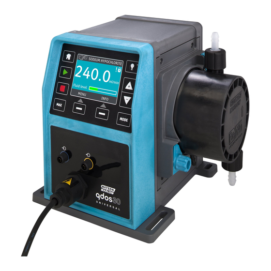
Qdos 30: Note: The appearance of the pump drive unit may vary from the that shown depending on the pump model. The hydraulic connector pack shown is an optional accessory. The following components are supplied with all qdos pumps: Pump drive unit ReNu pumphead User connection collars The designated power cable (attached to the pump drive unit) -
Page 10: Information For Returning Pumps
Information for returning pumps In compliance with the UK Health and Safety at Work Act and the Control of Substances Hazardous to Health Regulations, you are required to declare the substances which have been in contact with product (s) you return to Watson- Marlow or its subsidiaries or distributors. -
Page 11: Safety Notes
Safety notes In the interests of safety, this pump and pumphead should only be used by competent, suitably trained personnel after they have read and understood this manual, and considered any hazard involved. If the pump is used in a manner not specified by Watson- Marlow Limited, the protection provided by the pump may be impaired. - Page 12 Please refer to the chemical compatibility guide which can be found at: www.wmpg.com/chemical If you need to use the pump with any other chemical please contact Watson-Marlow to confirm compatibility Operation of the pump after failure of the consumable peristaltic tube may result in a flow of chemicals to the inside of the pumphead.
-
Page 13: Pump Specifications
Pump specifications qdos 20, 60 and 120: ReNu pumphead (left hand mounted) Mounting plate Pumphead locking latch Outlet (not Remote) Drive unit Inlet qdos 20, 60 and 120 with relay module: 110v or 24v relay module ReNu pumphead (left hand mounted) Mounting plate Pumphead locking latch... - Page 14 qdos 30: ReNu pumphead (left hand mounted) Mounting plate Pumphead retaining clamps Outlet (not Remote) Drive unit Inlet Power qdos 30 with 110v or 24v relay module: 110V or 24V relay module ReNu pumphead (left hand mounted) Mounting plate pumphead retaining clamps Outlet (not Remote)
-
Page 15: Pump Specifications
Manufacturer details Pump specifications Manual, PROFIBUS, Universal and Universal+: qdos120:0.1-2000 ml/min (20000:1) qdos60:0.1-1000 ml/min (10000:1) qdos30:0.1-500 ml/min (5000:1) qdos20:0.1-333 ml/min (3330:1) Flow Range (flow control) Remote: qdos120:1.25-2000 ml/min (1600:1) qdos60:0.6-1000 ml/min (1600:1) qdos30:0.3-500 ml/min (1600:1) qdos20:0.2-333 ml/min (1600:1) AC Supply voltage/frequency... -
Page 16: Standards (Ac Mains Power Supply)
AC Power consumption 190VA DC Supply voltage/frequency 12-24V DC (12/24VDC power option) DC Power consumption (12/24VDC 150W power option) Installation category (overvoltage category) An electrical mains supply is required ±10% of nominal voltage. Maximum along with cable connections to the best voltage fluctuation practice of noise immunity IP66 to BS EN 60529... -
Page 17: Standards (12-24V Dc Power Supply)
UL 61010A-1, UL/CSA 61010-1 CAN/CSA-C22.2 No 61010-1 IEC 61010-1 Other Standards Radiated emissions FCC 47CFR, Part 15 NEMA 4X to NEMA 250 NSF61 for pumphead Standards (12-24V DC power supply) Safety requirements for electrical equipment for measurement, control and laboratory use: BS EN 61010- 1 incorporating A2 Category 2, Pollution degree 2 EC Harmonised Degrees of protection provided by enclosures (IP code): BS EN... -
Page 18: Dimensions
Dimensions Dimension qdos20 qdos30 qdos60 qdos120 234mm (9.2”) 234mm (9.2”) 234mm (9.2”) 234mm (9.2”) 214mm (8.4”) 214mm (8.4”) 214mm (8.4”) 214mm (8.4”) 82.5mm 118mm (4.6”) 118mm (4.6”) 118mm (4.6”) (3.2”) 266mm 266mm 233mm (9.2”) 266mm (10.5”) (10.5”) (10.5”) E*—Optional relay modules (H or 43mm (1.7”) -
Page 19: Weights
Weights qdos20, 60 and 120: Drive Drive with pumphead Model Manual 10lb 2oz 12lb 9oz Remote 9lb 15oz 12lb 6oz Universal 10lb 2oz 12lb 9oz Universal+ 10lb 2oz 12lb 9oz PROFIBUS 10lb 2oz 12lb 9oz Universal 24V relay 10lb 9oz... -
Page 20: Good Pump Installation Practice
Please refer to the chemical compatibility guide which can be found at: www.wmftg.com/chemical. If you need to use the pump with any other chemical please contact Watson-Marlow to confirm compatibility. m-qdos-en-02... -
Page 21: Do's And Do Not's
Pressure capability qdos120 can be operated continuously at discharge pressures of up to 4 bar (60psi) qdos20, qdos30 and qdos60 can be operated continuously at discharge pressures of up to 7 bar (100psi). qdos30 can be operated at discharge pressures of up to 10 bar (145 psi), however flowrate and pumphead life will be affected. -
Page 22: Connecting To A Power Supply
Connecting to a power supply AC mains power supply This pump is fitted with a switch mode power supply and will operate from any mains voltage in the range ~100-240V AC, 50/60Hz supplies. Make suitable connection to an earthed, single-phase mains electricity supply. We recommend using commercially available supply voltage surge suppression where electrical noise may be present. -
Page 23: Dc Power Supply Option
DC power supply option The range of DC sources is intended to include: • Automotive— either mobile, such as trailer mounted, or static, such as a vehicle battery or auxiliary output • Conventional DC supplies derived from AC mains, such as 12V or 24V supplies powering PLCs •... -
Page 24: Start-Up Check List
Start-up check list Fit the pumphead to the drive. (See "Pumphead Replacement (qdos 30)" on page 112 or "Pumphead Replacement (qdos 20, 60 and 120)" on page 117) Ensure the pumphead ports are securely fitted to the interface tubing. Ensure proper connection has been made to a suitable power supply. Ensure that general... -
Page 25: Automatic Control Wiring - Universal, Universal+ And Remote Models Without Relay Modules
Interfacing the pump with other devices is by means of two IP66 rated five pole M12 connectors mounted on the front of the pump. M12 connectors with flying lead cables can be purchased as an accessory from Watson-Marlow. The function of each of the leads is labelled. -
Page 26: Input Pin Assignments At The Pump
10.1 Input pin assignments at the pump Pin 2 Pin 2 Pin 1 Pin 3 Pin 5 Pin 4 Input lead Function Specification Referenced to colour Connect 5-24V DC supply to stop (referenced to pin 4). Run/stop Min. 5V, max.30V Alternatively, connect pin 5 of the Brown output connector to this pin via... -
Page 27: Output Pin Assignments At The Pump
Remote stop Depending on the polarity set in the control settings menu, applying a 5V to 24V signal to pin 1 will STOP the pump in all operating modes. In manual and analogue mode, the pump will start when the signal is removed. The user can reconfigure this input in the control settings menu so that the pump will run when the signal is applied and stop when there is no signal to pin 1. - Page 28 Output Function Specification lead colour Analog out 4-20mA into 250Ω (referenced to pin 4) Blue Black Pin 5 supply voltage is 5V with impedance of 2.2k, this can be Supply Grey connected via a NO switch to input pin 1 or 2 to power the inputs. Example wiring for a "pull up resistor"...
-
Page 29: Optional Output Lead
On the Universal+ version there is also an option to match the scale of the 4-20mA input if this has been reconfigured by the user. This option is available in the Control settings menu. Note: If the mA output is to be used for reading from a multimeter, a 250Ω resistor is required in series. -
Page 30: Automatic Control Wiring - 24V Relay Module And 110V Relay Module (Universal And Universal+ Only)
Automatic control wiring - 24V relay module and 110V relay module (Universal and Universal+ only) The pump can be connected with other devices by means of the screw-terminal connectors within the relay module situated on the side of the pump. The relay module must be removed from the pump housing to allow suitable cables to be connected to the terminal connectors via the watertight cable glands on the module. -
Page 31: Wiring Up The Terminal Connectors
Refitting the relay module cover Ensure the sealing strip is undamaged and positioned within its channel on the side of the drive housing. Hold the module cover in place, taking care not to disturb the sealing strip. Starting with the top left screw, tighten the four retaining screws to 2.5Nm. - Page 32 For convenience of wiring more than 8 conductors per cable may be awkward to handle. 1. Use a suitable 21mm spanner to unscrew the sealing plugs. 2. Screw in the supplied ½” NPT cable glands complete with new sealing washers in place of the plug, ensuring that the retaining nut is properly seated.
- Page 33 6. Prepare the cable screen(s) by twisting a suitable length. The twisted length(s) shall ideally be sleeved to prevent shorting. 7. Secure the end of the cable screen to the Faston receptacles on the spade connectors provided. 8. Push the bared conductor into the square hole in the connector.
-
Page 34: Relay Module Pcb Connectors
11.3 24V relay module pcb connectors As you look at the module the pcb will appear in the same orientation as shown in the diagram below. Never apply mains power to the 4-20mA input, 4-20mA output,+24VDC or stop contact terminals. Apply the correct signals to the terminals shown below. - Page 35 RLY 2 Run status output (J4) Connect the output device to the C (common) terminal of the relay connector and either the N/C (normally closed) or N/O (normally open) terminal as required. This relay coil is energised when the pump is running. The default for Relay 2 is run status, on universal+ models this output (2) can be configured in the control settings menu.
- Page 36 Speed: analogue output (J1) (Universal+ only) A current analogue signal within the range 4-20mA is available between the O/P (output) terminal and the 4-20mA GND terminal. The current is fixed and directly proportional to the pump speed. 20mA = maximum speed, 4mA = zero speed.
-
Page 37: Relay Module Pcb Connectors
11.4 110V relay module pcb connectors As you look at the module the pcb will appear in the same orientation as shown in the diagram below. Apply the correct signals to the terminals shown below. Limit signals to the maximum values shown. Do not apply voltage across other terminals. - Page 38 RLY 2 Run status output (J4) Connect the output device to the C (common) terminal of the relay connector and either the N/C (normally closed) or N/O (normally open) terminal as required. This relay coil is energised when the pump is running. The default for Relay 2 is run status, on universal+ models this output (2) can be configured in the control settings menu.
- Page 39 Earth shielding terminals 4.8mm spade terminals are supplied for earth shielding of cables. The input cable and output cable earths can be connected to either terminal. 4-20mA and low voltage signals separate from mains power. Use separate glanded input cables m-qdos-en-02...
-
Page 40: Profibus Control Wiring
PROFIBUS control wiring Interfacing the pump with the PROFIBUS network is by means of an M12 connector mounted on a flying lead on the front of the pump. It is the user’s responsibility to ensure the safe and reliable operation of the pump under PROFIBUS control. -
Page 41: Pin Assignments At The Pump
12.2 Pin assignments at the pump Pin 5 Pin 3 Pin 4 Pin 2 Pin 1 Pin No. Signal Function +5V supply for terminating resistors RxD/TxD-N Data line minus (A-line) DGND Data ground RxD/TxD-P Data line plus (B-line) Shield Ground connection Note: If the pump is the last bus device connected to the PROFIBUS cable it must be terminated using terminating resistor (PROFIBUS standard EN 50170). -
Page 42: Switching On (Manual, Profibus, Universal And Universal+)
Switching on (Manual, PROFIBUS, Universal and Universal+) 13.1 Switching on the pump for the first time (Manual, PROFIBUS, Universal and Universal+ only) Power-up the pump. The pump displays the start- up screen with the Watson- Marlow Pumps logo for three seconds. - Page 43 The pump is preset with operational parameters as shown in the table below: First-time start-up defaults qdos120:960ml/min qdos60:480ml/min Flow rate Pump status Stopped qdos30:240ml/min qdos20:120ml/min qdos120:16 ml/rev qdos60:6.67ml/rev Calibration Flow unit ml/min qdos30:8 ml/rev qdos20:4 ml/rev Backlight 30 minutes Pump tag WATSON-MARLOW Auto restart This then proceeds to the home screen. m-qdos-en-02...
-
Page 44: Switching The Pump On In Subsequent Power Cycles (Manual, Profibus, Universal And Universal+ Only)
The pump runs a power- on test to confirm proper functioning of the memory and hardware. If a fault is found, an error code is displayed (see "Error codes" on page 108). The pump displays the start-up screen with the Watson-Marlow Pumps logo for three seconds followed by the home screen. -
Page 45: Switching On (Remote)
Switching on (Remote) When power is supplied to the pump, all the LED icons will illuminate for three seconds. After this period the pump will operate in accordance with the inputs received. m-qdos-en-02... -
Page 46: Pump Operation
Pump operation Note: Sections "Keypad functions (Manual, PROFIBUS, Universal and Universal+ only)" below up to and including "Help (Manual, PROFIBUS, Universal and Universal+ only)" on page 105 apply to Manual, PROFIBUS, Universal and Universal+ only. It is only possible to control the Remote pump via the input and output, (I/O) provided. 15.1 Pump operation (Remote pump) The remote pump will operate proportionally to the analog signal provided. - Page 47 This key can be used to prime the pump when in manual mode. When pressed the pump will operate at maximum flow rate. FUNCTION KEYS When pressed will perform the function displayed on the screen directly above the relevant function key. After 30 minutes of no keypad activity, the HMI display will dim to 50% brightness.
- Page 48 Switching between modes (Manual, PROFIBUS, Universal and Universal+ only) Note: Remote model does not feature selectable modes. Using +/- keys will scroll through the available modes. The available modes are: Manual (default) Flow calibration Analog 4–20mA (Universal and Universal+ only) Contact mode (Universal+ only) PROFIBUS (PROFIBUS only) Fluid recovery...
-
Page 49: Manual Mode (Manual, Profibus, Universal And Universal+ Only)
Manual mode (Manual, PROFIBUS, Universal and Universal+ only) All settings and functions of the pump in manual mode are set and controlled by means of key-presses. Immediately after the start-up display sequence (detailed in: "Switching the pump on in subsequent power cycles (Manual, PROFIBUS, Universal and Universal+ only)" on page 44 ), the manual mode home screen will be displayed unless auto restart is enabled. - Page 50 STOP Stops the pump. The display background changes to white. If the pump is not running pressing this has no effect. INCREASING AND DECREASING FLOWRATE Using the +/- keys will increase or decrease the flowrate. Decreasing flowrate: A single key press will decrease flowrate by the least significant digit of the chosen flowrate unit.
- Page 51 Increasing flow rate: A single key press will increase flowrate by the least significant digit of the chosen flowrate unit. Repeat key-presses as required to achieve the desired flowrate. Hold down the key for flowrate scrolling. Max 100% function (Manual mode only) Press and hold the MAX key to run at maximum flow.
-
Page 52: Profibus Mode(Profibus Only)
PROFIBUS mode(PROFIBUS only) In this operating mode PROFIBUS control can be enabled or disabled. The qdos PROFIBUS pump is designed so that the station address can only be set from the pump. The user can set the station address within this mode. Select MODE Using the +/- keys scroll to PROFIBUS and press SELECT If PROFIBUS is not enabled, the screen below will prompt you to CONFIRM that you would... -
Page 53: Assigning The Profibus Station Address At The Pump
Pressing the INFO function key will display further information. 17.1 Assigning the PROFIBUS station address at the pump The station address can only be set from PROFIBUS settings. The station address cannot be automatically assigned by the master. Select MODE Using the +/- keys scroll to PROFIBUS and press SETTINGS m-qdos-en-02... - Page 54 Using the +/- keys alter the station address, in the range from 1 to 125. (126 is the default station address). Press FINISH to set the station address, or NEXT to enable/disable PROFIBUS communication. Use the +/- keys to enable or disable PROFIBUS communication and press FINISH. m-qdos-en-02...
-
Page 55: Profibus Communication Errors
17.2 PROFIBUS communication errors In PROFIBUS mode, the screen below is displayed, the P indicates data exchange is happening. This screen will only be displayed after successful implementation of Master Slave communications, which always follow the sequence described below. Power ON / reset of Master or Slave Power ON Reset Download of parameters into the field device (selected Parameterisation... -
Page 56: Profibus Gsd File
The GSD file, filename: WAMA0E7D.GSD ;************************************************************************* *********** ======================================================= ========================= * ;* * ;* Watson-Marlow Bredel Pumps * ;* Bickland Water Road * ;* Falmouth * ;* Cornwall * ;* TR11 4RU * ;* Tel.: +44(1326)370370 * ;* FAX.: +44(1326)376009 *... - Page 57 ;* * ======================================================= ========================= * ;* Filename: WAMA0E7D.GSD * ;* GSD file version 3 from 2013-09-24 * ;* -------------------------------------------------------------------------------- * ;* * ;************************************************************************* *********** #Profibus_DP GSD_Revision = 3 Vendor_Name = “Watson Marlow” Model_Name = “Qdos Profibus Pump” Revision = “Version 3.00” Ident_Number = 0x0E7D Protocol_Ident = 0 Station_Type = 0...
-
Page 58: User Parameter Data
MaxTsdr_1.5M=150 MaxTsdr_3M=250 MaxTsdr_6M=450 MaxTsdr_12M=800 Slave_Family = 0 Implementation_Type = “VPC3+S” Info_Text=”PROFICHIP: PROFIBUS DPV0 - slave, Watson Marlow Qdos” Bitmap_Device = “WAMA_1N” Freeze_Mode_supp=1 Sync_Mode_supp=1 Fail_Safe=1 Auto_Baud_supp=1 Set_Slave_Add_supp=0 Min_Slave_Intervall=6 Modular_Station=0 Max_Diag_Data_Len=34 Max_User_Prm_Data_Len = 9 Ext_User_Prm_Data_Const(0)= 0x00,0x00,0x00,0x00,0x00,0x00,0x00,0x00,0x00 Module=”WM Pump, 3/14 word out/in” 0x62,0x5D EndModule 17.4 User Parameter Data... -
Page 59: Profibus Data Exchange
8 bit Byte 7 Fail Safe 8 bit Byte 8 Fail Safe Speed (Low byte of 16-bit unsigned) 8 bit Byte 9 Fail Safe Speed (High byte of 16-bit unsigned) Set Min/Max Speeds The Min/Max Speed parameters are used to set the minimum and maximum speed from the PROFIBUS interface. - Page 60 Cyclic Data Write (from Master to pump) 16 bit Byte 5 (low), 6 (high) Set Flow Calibration in μl per revolution Control Word Description Motor running (1= Running) Direction (0= CW, 1= CCW) Motor revolution counter reset (1=Reset count) Reserved Enable User Parameter Min/Max Speeds (1= Enabled) Enable Fieldbus master to set Flow Calibration (1= Enabled) Ignore leak detection sensor...
- Page 61 If a leak is detected the leak detect screen (16.1 Leak detection on page 54) will not be displayed. Bit 10 of the status word will be activated to indicate that a leak has occurred and the pump will continue to run until the Master indicates what action should be taken. Cyclic Data Read (from pump to Master) Cyclic data read (from pump to Master) 16 bit...
-
Page 62: Device-Related Diagnostic Data
Pumphead Speed The pumphead speed is a 16-bit unsigned integer value that represents the speed of the pump head in 1/10th of RPM. For example 1205 represents 120.5 RPM. Hours Run The hours run parameter is a 16 bit unsigned integer and will represent whole hours of runtime. - Page 63 Byte 26 Header Byte 27 Channel type Byte 28 Channel-related error code Channel-related diagnostic data Byte 3 Global error =0xA9 (General error) Over current =0xA1 (Short circuit) Under voltage =0xA2 (Under voltage) Over voltage =0xA3 (Over voltage) =0xA3 (Over voltage) Motor stall =0xA4 (Overload) Over temp =0xA5 (Over temp)
-
Page 64: Flow Calibration Mode (Manual, Profibus, Universal And Universal+ Only)
Flow calibration mode (Manual, PROFIBUS, Universal and Universal+ only) This pump displays flow rate in ml/min. Setting the flow calibration Select MODE Using the +/- keys, scroll to Flow calibration and press SELECT. Using the +/- keys enter the maximum flow rate limit and press ENTER. m-qdos-en-02... - Page 65 Press START to begin pumping a volume of fluid for calibration. Press STOP to stop pumping fluid for the calibration. m-qdos-en-02...
- Page 66 Using the +/- keys enter the actual volume of fluid pumped. To accept the new calibration press ACCEPT or RECALIBRATE to repeat the procedure. Press HOME or MODE to abort. The pump is now calibrated. m-qdos-en-02...
-
Page 67: Analog 4-20Ma Mode (Universal And Universal+ Only)
The default values stored in the pump are: A—4.1mA, 0 rpm B (qdos20)—19.8mA, 55 rpm B (qdos30,qdos60 and qdos120)—19.8mA, 125 rpm Flowrate When the mA signal received is greater than the level defined by point A, the run status output will be energised as the pump is running. - Page 68 To select Analog 4-20mA mode: Select MODE. Using the +/- keys, scroll to Analog 4-20mA and press SELECT. The current signal being received by the pump is displayed, for information only, on the HOME screen. Pressing the INFO function key will display further information. m-qdos-en-02...
- Page 69 Press the INFO key again to display the 4-20mA calibration figures. Analog Scaling Factor The Scaling Factor is a method of adjusting the 4-20mA profile by using a multiplication factor. Press +/- from the HOME screen to access the scaling factor. Use the +/- keys to enter a multiplication factor.
- Page 70 Press SELECT once you have chosen the required factor. Press ACCEPT to confirm the new 4-20mA PROFILE figures. This will not alter the stored A and B points, the multiplication factor will re- scale the 4- 20mA profile. To re- set the original flow rates re-set the multiplication factor to 1.00.
- Page 71 The speed limit function takes precedence over the scaling factor. For example if the qdos20 4-20mA profile is 0% flow at 4mA to 100% flow at 20mA and a speed limit of 33 rpm is applied, followed by a scaling factor of 0.5, then the output will be 30%. If a scaling factor of 2 is applied in the same scenario then the output will be 33 rpm or 60%, as the speed limit takes precedence over the scaling factor.
-
Page 72: Calibrate The Pump For 4-20Ma Control (Universal+ Only)
19.1 Calibrate the pump for 4-20mA control (Universal+ only) This feature is only available in the Universal+ model. The pump must be stopped before attempting to calibrate the 4-20mA values. High and low signals must be within range. If the signal sent is out of range you will not be able to set the signal input value and progress to the next step in the process. - Page 73 Setting a high signal Send the high signal input to the pump, or enter the current value using the +/- keys. ACCEPT appears when high mA signal is within tolerance limits. Press ACCEPT to accept the high signal input or CANCEL to return to the previous screen. m-qdos-en-02...
- Page 74 Setting high flow calibration Using the +/- keys scroll to the desired flow rate. Select SET FLOW or press BACK to return to the previous screen. Setting a low signal Send the low signal input to the pump, or enter the current value using the +/- keys. m-qdos-en-02...
- Page 75 If the range between the low and high signal is less than 1.5mA, the following error message will be displayed. ACCEPT appears when low mA signal is within tolerance limits. Press ACCEPT to accept the low signal input or CANCEL to return to the previous screen. m-qdos-en-02...
- Page 76 Setting low flow calibration Using the +/- keys scroll to the desired flow rate. Select SET FLOW. This proceeds to the screen confirming calibration is complete. Select CONTINUE to start in proportional mode or MANUAL to continue in manual mode. m-qdos-en-02...
-
Page 77: Contact Mode (All Universal And Universal+ Models Except 110V Relay Versions)
Contact Mode (All Universal and Universal+ models except 110V relay versions) In this operating mode the pump will meter a specific dose of fluid when an external pulse is received. The dose volume is a user defined value between 0.1ml and 999l. 20.1 Contact settings To setup contact mode, firstly you will need to define the settings. - Page 78 Use NEXT to move the selection bar to the next setting. Use +/- to alter the value of the highlighted setting: The contact dose is the volume of fluid the pump will dispense when an external pulse is received on input pin 2. The flow rate will determine the time taken to complete each dose.
-
Page 79: Contact Operating Mode (All Universal And Universal+ Models Except 110V Relay Versions)
20.2 Contact operating mode (All Universal and Universal+ models except 110V relay versions) To enter contact mode press the MODE key, move the selection bar to Contact, and press SELECT. The contact mode home screen will be displayed. The home screen displays the contact dose, the flow rate, and the dose time remaining when a dose is in progress. -
Page 80: Fluid Recovery Mode (Manual, Profibus, Universal And Universal+ Only)
Pulse dosing as an operation mode has its limitations. From an application perspective it is often not the most efficient method of achieving concentration consistency due to the pump only metering when a pulse is received, as opposed to continuously running in proportion to the flow. - Page 81 If the pump is already running then the following screen will be displayed. The pump must be stopped before it can be reversed to recover fluid. Press STOP PUMP. An instruction is now displayed. There is a warning to ensure that your system design permits reverse flow.
-
Page 82: Remote Fluid Recovery (Universal And Universal+ Models Without Relay Modules)
Release RECOVER to stop running the pump in reverse. 20.4 Remote fluid recovery (Universal and Universal+ models without relay modules) It is possible to run the pump in reverse and recover fluid automatically in the analog 4- 20mA mode. To achieve this, it is necessary to enable remote fluid recovery functionality. To enable this position the selection bar over fluid recovery in the mode menu and press the SETTINGS function key. - Page 83 This operating method allows for fluid recovery from your delivery line. It should not be used for bulk fluid transfer. Once enabled, remote fluid recovery should be operated in the following sequence: 1. Send a remote stop signal (apply 5 - 24 volts to input pin 1). 2.
-
Page 84: Main Menu (Manual, Profibus, Universal And Universal+ Only)
Main menu (Manual, PROFIBUS, Universal and Universal+ only) To access the main menu press the MENU button from one of the HOME screens or INFO screens. For example: Manual HOME screen Manual INFO screen This will display the main menu as shown below. Use the +/- keys to move the selection bar between the available options. -
Page 85: Fluid Level Monitor (Manual, Profibus, Universal And Universal+ Only)
21.1 Fluid level monitor (Manual, PROFIBUS, Universal and Universal+ only) The fluid level monitor can be used to estimate the fluid level left in your supply tank. When activated, the pump will display a bar on the home screen indicating the volume of fluid in the tank. - Page 86 After pressing ENABLE, the pump will display the fluid level setup options. If you press DISABLE the pump will deactivate the fluid level monitor. The fluid bar will no longer appear on the HOME screens. The fluid volume unit can be changed by pressing the US GALLONS or LITRES key, the key name will change depending upon the unit selected.
- Page 87 Enter the maximum level of your reservoir or supply container using the +/- keys to adjust the volume. Press NEXT when you are happy you have the correct volume. Now use the +/- keys to set the alert level. In the screen above the alert level is set to 20%.
- Page 88 If you need to adjust the volume of fluid in the tank, for example when re-filling, then press SELECT when the bar highlights the Adjust level option. You can now use the +/- keys to adjust the level of fluid in the tank. The accuracy of the fluid level monitor will improve with regular calibration of the pump.
-
Page 89: Security Settings (Manual, Profibus, Universal And Universal+ Only)
21.2 Security settings (Manual, PROFIBUS, Universal and Universal+ only) Security settings can be changed by selecting SECURITY SETTINGS from the Main menu. Auto keypad lock Press ENABLE/DISABLE to switch on/off the Auto keypad lock. When active the keypad will ‘lock’ after 20 seconds of inactivity. Once locked it will display the screen below when any key is pressed. - Page 90 The padlock icon will appear on the operating mode home screen to show that keypad lock is activated. Note that the STOP and BACKLIGHT keys will always work whether the keypad is locked or not. PIN protection Using the +/- keys in the security settings menu, highlight PIN protection. Press ACTIVATE/DEACTIVATE to switch on/off the PIN protection.
- Page 91 To define a four digit number for your PIN, use +/- to select each digit from 0-9. Once you have the required digit press the NEXT DIGIT key. After selecting the fourth digit press ENTER. Now press CONFIRM to check that the number entered is the PIN you require. Press CHANGE to return to PIN entry.
-
Page 92: General Settings (Manual, Profibus, Universal And Universal+ Only)
If you enter an incorrect PIN it will display the following screen: There is an override feature, should you forget your PIN. Please contact Watson-Marlow for details of how to reset the PIN. 21.3 General settings (Manual, PROFIBUS, Universal and Universal+ only) To view the general settings menu, select GENERAL SETTINGS from the main menu. - Page 93 Auto restart Press ENABLE/DISABLE to turn the auto restart feature on/off. This pump offers an auto restart feature. If active on power loss, it restores the pump when power returns to the operating state it was in when power was lost. For example, if the pump was running in analog mode prior to power loss, it would return to the same operating mode and continue to run at a proportional speed to the analog input.
- Page 94 Flow units The current chosen flow unit is displayed on the right hand side of the screen. To change flow units move the selection bar over the flow unit menu entry and press SELECT. Use the +/- keys to move the selection bar over the required flow unit. Press SELECT to define the flow units to use.
- Page 95 SELECT. If a pump label has been previously defined, this will be displayed on screen to allow editing, otherwise it will display the default label “WATSON-MARLOW”. Use the +/- keys to scroll through the available characters for each digit. The available characters are 0-9, A-Z, and SPACE.
- Page 96 Restore defaults To restore the factory default settings, select restore defaults from the general settings menu. There are two confirmation screens to ensure that this function is not carried out in error. Press CONFIRM followed by RE-CONFIRM to reset the defaults. Language Select language from the general settings menu to choose an alternative display language for the pump.
-
Page 97: Mode Menu (Manual, Profibus, Universal And Universal+ Only)
Your selected language will now be displayed on screen. Press CONFIRM to continue, all displayed text will now appear in your chosen language. Press REJECT to return to the language choice screen. 21.4 MODE menu (Manual, PROFIBUS, Universal and Universal+ only) Selecting MODE menu from the main menu will navigate you to the MODE menu. -
Page 98: Control Settings (Manual, Profibus, Universal And Universal+ Only)
The maximum speed the qdos30, qdos60 or qdos120 pump is capable of running at is 125 The maximum speed the qdos20 pump is capable of running at is 55 rpm. Select Speed limit from the control settings menu to define a lower maximum speed limit for the pump. - Page 99 If you require this functionality on a software version lower than 2.0 please use the 4-20mA calibration method described in Section 15 or contact Watson-Marlow aftersales department to discuss other control methods. If the version is MKS-2.0 or higher, the speed limit setting may be used.
- Page 100 Reset run hours Select reset run hours from the control settings menu. Select RESET to zero the run hours counter. The run hours counter can be viewed by pressing INFO from your home screen. Reset volume counter Select reset volume counter from the control settings menu. Select RESET to zero the volume counter.
- Page 101 Configurable outputs - Universal+ model Select Configure outputs from the control settings menu. Output 1 and Output 2 Use +/- and SELECT to choose which output to configure. m-qdos-en-02...
- Page 102 Use +/- and SELECT to choose which pump status you require for the chosen output. The tick symbol indicates the current setting. Use +/- and SELECT to choose the logic state of the chosen output. Press SELECT to program the output or Exit to cancel. m-qdos-en-02...
- Page 103 4-20mA Output (Universal+ model only) Select 4-20mA to configure the pumps 4-20mA output response. Use +/- and SELECT to choose the required setting Full scale – The 4-20mA output will be based on the full speed range of the pump. At 0 rpm the pump will output 4mA.
- Page 104 Configurable Start/Stop input Select Configure start/stop input from the menu. Use +/- and SELECT to configure the input setting. A low stop input is recommended as the pump will be stopped in the event of any loss of input signal. m-qdos-en-02...
-
Page 105: Help (Manual, Profibus, Universal And Universal+ Only)
21.6 Help (Manual, PROFIBUS, Universal and Universal+ only) Select Help from the main menu to access the help screens. m-qdos-en-02... -
Page 106: Status Leds (Remote Only)
Status LEDs (Remote only) The remote pump has LED icons on the front panel to indicate its status. A description of the icons and definition of each error state is provided in the table below. LED Icons 4-20mA Status Change Running Remote stop 4-20mA signal... -
Page 107: Troubleshooting
Troubleshooting If the pump display remains blank when the pump is switched on, make the following checks: Check that mains power is available to the pump. Check the fuse in the wall plug if one is present. If the pump runs but there is little or no flow, make the following checks: Check that fluid is supplied to the pump. -
Page 108: Error Codes
If the message constantly repeats after several pumphead installations, then there may be a leak detection sensor failure. Please contact Watson-Marlow for repair. If you need to bypass a faulty leak detection sensor then you can do so by pressing IGNORE. -
Page 109: Error Indication (Remote Only)
Error Error condition Suggested action code Stop pump immediately. Power OFF / ON may reset. Or Er14 Speed error seek support Stop pump immediately. Power OFF / ON may reset. Or Er15 Over current seek support Stop pump immediately. Check supply. Power OFF/ON Er16 Over voltage may reset... -
Page 110: Technical Support
Technical support Watson-Marlow Limited Falmouth Cornwall United Kingdom TR11 4RU Telephone Number: +44 (0)1326 370370 Email: aftersales.uk@wmftg.com Web: www.wmftg.com m-qdos-en-02... -
Page 111: Drive Maintenance
Drive maintenance There are no user serviceable parts inside the pump. The unit should be returned to Watson-Marlow for service. See "Information for returning pumps" on page 10. m-qdos-en-02... -
Page 112: Pumphead Replacement (Qdos 30)
Pumphead Replacement (qdos 30) The pumphead is a consumable part and cannot be serviced. Pumphead Left hand retaining clamps mounted pumphead Ensure contaminated pumpheads are not shipped but disposed of locally according to regulations for contaminated items and health and safety procedures. - Page 113 5. Remove input and output connections from the pumphead. 6. Fully loosen the two pumphead retaining clamps. 7. To disengage the pumphead from the retaining clamps, carefully detach the pumphead from the pump housing and rotate it in an anti-clockwise direction by approximately 15°.
- Page 114 8. Remove the pumphead from the pump housing. 9. Safely dispose of the used pumphead according to your own health and safety regulations. Take care to comply with any safety requirements of the chemical being pumped. Fitting a new pumphead Fitting a new pumphead is a reverse procedure of the pumphead removal.
-
Page 115: Connecting Interface Tubing
6. Apply mains power to the pump, press start and run the pumphead for a few revolutions. 7. Stop the pump and isolate it from the mains power supply, then tighten the clamps further if necessary. 26.1 Connecting interface tubing Note: Please refer to the diagram below in conjunction to the text when connecting interface tubing to the pumphead. - Page 116 Note: Hydraulic connector packs are optional accessories. See "Spares and accessories" on page 124. Hose barbs 1. Detach the desired connector from the sprue (2). 2. Place user connection collar over the chosen fitting and tighten onto the pumphead (2a). 3. Press tube onto connector until it reaches the back face. 4.
-
Page 117: Pumphead Replacement (Qdos 20, 60 And 120)
Pumphead Replacement (qdos 20, 60 and 120) The pumphead is a consumable part and cannot be serviced. Pumphead locking left hand mounted latch pumphead Ensure contaminated pumpheads are not shipped but disposed of locally according to regulations for contaminated items and health and safety procedures. - Page 118 5. Remove input and output connections from the pumphead. 6. Release the pumphead retaining lever. 7. To disengage the pumphead from the drive, rotate it in a clockwise direction by approximately 15°. 8. Safely dispose of the used pumphead according to your own health and safety regulations.
- Page 119 Fitting a new pumphead Fitting a new pumphead is a reverse procedure of the pumphead removal. 1. Remove the new pumphead from its packaging. Align the new pumphead with the pump drive shaft and slide into position on the pump housing. 3.
-
Page 120: Connecting Interface Tubing
27.1 Connecting interface tubing Note: Please refer to the diagram below in conjunction to the text when connecting interface tubing to the pumphead. Before connecting the interface tubing, ensure that the supplied Santoprene seals (1) are correctly fitted in the head ports (1a) and that the Santoprene seals and connector material is compatible with pumped fluid. - Page 121 Hose barbs 1. Detach the desired connector from the sprue (2). 2. Place user connection collar over the chosen fitting and tighten onto the pumphead (2a). 3. Press tube onto connector until it reaches the back face. 4. Secure with suitable retaining clip. Threaded connectors 1.
- Page 122 M24 x 2mm 5 x 8 10 x 16 6.3 x 11.5 9 x 12 5 x 8 10 x 16 6.3 x 11.5 9 x 12 m-qdos-en-02...
-
Page 123: Ordering Information
Ordering information 28.1 Pump part numbers • • • • • • Plug options Model Model 1: Remote A: US 1: Qdos 20 Pumphead E: European 3: Manual 2: Qdos 30 Tube material † orientation* U: UK 4: Universal 3: Qdos 60 K: Australia 2: Santoprene L = Left... -
Page 124: Spares And Accessories
Spares and accessories Image Description Part number qdos30 0M3.2200.PFP ReNu Santoprene pumphead qdos60 0M3.3200.PFP (PFPE lubricant) qdos120 0M3.4200.PFP qdos20 0M3.1800.PFP ReNu SEBS pumphead (PFPE qdos30 0M3.2800.PFP lubricant) qdos60 0M3.3800.PFP Hydraulic connection pack, polypropylene compression 0M9.221H.P01 fittings Hydraulic connection pack, polypropylene barb/threaded 0M9.221H.P02... - Page 125 Image Description Part number Hydraulic connection pack, polypropylene, 1/2” hose barb 0M9.401H.P05 Hydraulic connection pack, PVDF, threaded fittings, 1/2” BSP 0M9.401H.F03 Hydraulic connection pack, PVDF, threaded fittings, 1/2” NPT 0M9.401H.F04 Hydraulic connection pack, PVDF, 1/2” hose barb 0M9.401H.F05 P V C Interface tubing, pvc 6.3x11.5mm, 2m (6.5ft) length 0M9.2222.V6B P V C...
- Page 126 Image Description Part number P o l y e t h y l e n e Interface tubing, polyethylene 5x8mm, 2m (6.5ft) length 0M9.2222.E58 P o l y e t h y l e n e Interface tubing, polyethylene 9x12mm, 5m (16ft) length 0M9.2225.E9C P o l y e t h y l e n e Interface tubing, polyethylene 5x8mm, 5m (16ft) length...
-
Page 127: Performance Data
Pressure capability qdos120 can be operated continuously at discharge pressures of up to 4 bar (60psi) qdos20, qdos30 and qdos60 can be operated continuously at discharge pressures of up to 7 bar (100psi). qdos30 can be operated at discharge pressures of up to 10 bar (145 psi), however flowrate and pumphead life will be affected. -
Page 128: Performance Curves
29.6 Performance curves The graphs below show flow rates for suction and discharge pressures for the pumphead. Suction gauge pressure / psi Discharge gauge pressure / psi 2200 2000 1800 1600 Santoprene tubing 1400 1200 1000 Santoprene or SEBS tubing Santoprene tubing only qdos 120 qdos 60... -
Page 129: Trademarks
Trademarks Watson- Marlow, qdos, qdos20, qdos30, qdos60, qdos120 and ReNu are trademarks of Watson-Marlow Limited. m-qdos-en-02... -
Page 130: Publication History
Publication history m-qdos-en-02 Watson-Marlow qdos 20, 30 60 and 120 User Manual First published 09 2018 m-qdos-en-02...
Need help?
Do you have a question about the qdos20 and is the answer not in the manual?
Questions and answers