
Related Manuals for Watson-Marlow DriveSure 100 Series


Summary of Contents for Watson-Marlow DriveSure 100 Series
- Page 1 Reference Manual DriveSure ADC DriveSure En DriveSure Pn Date of publication: 19 April 2024 Version of publication: Language of publication...
-
Page 2: Preface
Preface Disclaimer The information contained in this document is believed to be correct, but Watson-Marlow accepts no liability for any errors it contains and reserves the right to alter specifications without notice. If the product is used in a way that is not intended or described in these instructions, the protection, performance, and/or lifespan may be negatively affected. -
Page 3: Table Of Contents
Table of contents Preface Disclaimer Translation of the original instructions Introduction to the document User groups Information types Trademarks Safety Safety symbols Safety signals Personal Protective Equipment (PPE) Product overview Introduction WM Connect PC Software General arrangement Intended use Pump models Accessories Product labels... - Page 4 Installation—Chapter 2: Electrical power Part 1: Chapter installation requirements, specification, and information Part 2: Chapter installation procedures Installation—Chapter 3 Overview: Remote Control Installation—Sub-Chapter 3A: Remote Control: DriveSure ADC 11.1 Part 1: Sub-Chapter installation requirements, specification, and information 11.2 Part 2: Sub-Chapter installation procedures Installation—Sub-Chapter 3B: Remote Control: DriveSure En 12.1 Part 1: Sub-Chapter installation requirements, specification, and...
- Page 5 Errors, breakdown, and troubleshooting 20.1 Errors 20.2 Error reporting 20.3 Breakdown 20.4 Troubleshooting 20.5 Technical support 20.6 Warranty 20.7 Returning products Chemical compatibility 21.1 Overview 21.2 Materials of construction 21.3 Procedure to check chemical compatibility Compliance 22.1 Compliance marking 22.2 Certification and declaration...
-
Page 6: Introduction To The Document
Introduction to the document User groups These instructions are the installation and maintenance instructions, for a Watson-Marlow DriveSure (ADC, En, or Pn) pump, for reference during the products life cycle. There are two main user groups as defined below:... -
Page 7: Trademarks
EtherNet/IP is a registered trademark of ODVA, Inc.. Watson-Marlow, Pumpsil, PureWeld, LoadSure, LaserTraceability, Bioprene and Marprene are registered trademarks of Watson-Marlow Limited. STA-PURE PCS and STA-PURE PFL and Style 400 are trademarks of WL Gore & Associates Inc.. ... -
Page 8: Safety
This symbol identifies that an appropriate safety Potential hazard instruction should be followed or a potential hazard exists 3.1.1 Replacing safety labels If the safety labels on the product become accidentally damaged, contact your local Watson-Marlow representative for information on obtaining replacements. 3 Safety... -
Page 9: Safety Signals
Safety signals Signals indicate a possible hazard. Signal are used in these instructions when immediately relevant to the information, task or procedure. 3.2.1 Signals: With risk of personal injury Signals indicating risk of a personal injury are presented when relevant to a task in this format: CAUTION The CAUTION signal word indicates a hazard. -
Page 10: Personal Protective Equipment (Ppe)
Personal Protective Equipment (PPE) The following minimum PPE will be required for any task or procedure in these instructions. 1. Safety glasses 2. Safety boots 3. Gloves chemically compatible with the chemicals being pumped A risk assessment by a responsible person must be undertaken to identify if: ... -
Page 11: Product Overview
This section provides a product and specification overview. Introduction Watson-Marlow DriveSure integrates motor, mounting, our latest generation control technology, and WM Connect PC software to deliver powerful performance. Designed for integration into equipment, such as a cabinet or casing. All DriveSure models are positive displacement peristaltic pumps, fully tested and certified, ensuring reliability in a range of applications. ... -
Page 12: General Arrangement
General arrangement A general arrangement illustration is provided below: Item Name Picture showing item Number Pump drive Peristaltic pumphead Pumphead mounting plate Peristaltic (tubing or element) Connection to process fluid path Process fluid path Intended use All DriveSure models are designed as components requiring integration into other equipment or system, prior to use;... -
Page 13: Pump Models
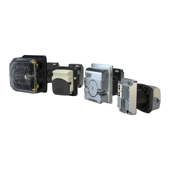
Pump models A DriveSure pump is a combination of A DriveSure drive model A Watson-Marlow pumphead model The model variation, general arrangement, and features of each of these components are explained in the following sub-sections. 4.5.1 Drive: Models There are 3 models of drive ... - Page 14 4.5.2 Drive: General arrangement The general arrangement of a DriveSure drive is illustrated below 520R2DriveSureEn2.4 mm WT model shown, the exact appearance and arrangement will vary with model. Item Number Name Integrated Controller Motor Connection for integrated cover-open sensor cable Connection for prime switch cable Mounting plate alignment features Threaded brass inserts for pump mounting bolts...
- Page 15 4.5.3 Pumphead: Models A DriveSure pump may be ordered with any of the following Watson-Marlow pumpheads. Pumphead Series Pumphead models Image 114DV 100 Series 114DVP 313D 313D2 300 Series 314D 314D2 400 Series RXMD ...
- Page 16 4.5.4 Pumphead: General arrangement The general arrangement of a pumphead is provided in the image below 100 Series 300 Series 400 Series 500 Series Item Number Name Pumphead cover Rotor Tubing clamps Peristaltic tubing (or element) Pumphead mounting plate ...
- Page 17 A Watson-Marlow pumphead, provides fluid flow, by the principle of positive displacement, using a Watson-Marlow peristaltic tube installed inside the pumphead. 4.5.5.1 Tubing: types Watson-Marlow pumpheads are designed for use with two main types of peristaltic tubing: Tubing type Fluid connection style Picture...
- Page 18 Continuous tubing with a 2.4 mm wall thickness 313D2, 314D2, 520R2 Watson-Marlow LoadSure elements 520REL, 520REM Not all tubing is available in all materials, all sizes, all lengths, or all types (continuous, element). Contact your local Watson-Marlow representative for specific availability. 4 Product overview...
-
Page 19: Accessories
These can be ordered separately with the correct country plug. Contact your local Watson-Marlow representative for more information. Do not fit any devices or accessories other than those approved by Watson-Marlow or as specified in these instructions. 4 Product overview... -
Page 20: Product Labels
Product labels 3 labels are provided on the product (DriveSureEn model shown): Number Name Picture DC Power supply requirement Date of manufacture Functional earth terminal Ambient operating temperature Network MAC Address Network port numbers Product serial number Product part number Safety symbols QR code for instructions... -
Page 21: Product Code
Product code A DriveSure pump product code is a unique string of numbers as illustrated by the graphic and tables in the subsections below: 4.8.1 100 series Product Control Cable Pumphead Pumphead Pressure length colour 0 = Complete 4 = ADC 1 = 1 m (3.28 ft) 0 = No 0 = No... - Page 22 4.8.2 300 series Pumphead Cable length Product Control colour 0 = Complete pump 4 = ADC 1 = 1 m (3.28 ft) cable 0 = No pumphead 6 = Drive only 8 = En 3 = 3 m (9.84 ft) cable 1 = Standard colour (EtherNet/IP) 9 = Pn...
- Page 23 4.8.3 400 Series Control Cable length Direction Tube bore Pressure size 4 = ADC 1 = 1 m (3.28 ft) 1 = Clockwise (CW) 4 = 4 bar 3 = 1.6 mm cable 8 = En 3 = 3 m (9.84 ft) 2 = Counter clockwise 6 = 6 bar 4 = 3.2 mm...
- Page 24 4.8.4 500 series F–G Product Control Cable Pumphead Pumphead Pumphead length Colour Model 4 = ADC 1 = 1 m 0 = No 0 = No 00 = No Complete (3.28 ft) pumphead pumphead pumphead pump cable 6 = Drive 8 = En 3 = 3 m 1 = Standard...
-
Page 25: Specification Overview
Specification overview This section provides an overview of specification. Detailed installation specification is provided when relevant to the installation task. 4.9.1 Performance overview The flowrate of the pump depends on Speed of the pump Pumphead Tubing material ... - Page 26 4.9.2 100 Series performance 4.9.2.1 100 Series 48 V DC performance summary table Flow rates in the table below are based on the following conditions: Pumping water at 20 °C in a 0 bar inlet and discharge pressure application ...
- Page 27 4.9.2.2 100 Series 48 V DC performance curve The flowrate versus application pressure of a 114DV or 114DVP pumphead under the following conditions is shown in the performance curves: 48 V DC power supply Marprene tube Pumping water at 20 °C ...
- Page 28 The following conditions may influence achievable flow rates: Other power supply voltages Other fluid viscosities Other tubing materials Different speeds than 100 rpm A clockwise direction Achievable flow rates should be determined in a user's system through application testing. 4 Product overview...
- Page 29 4.9.3 300 Series performance 4.9.3.1 300 Series 48 V DC performance summary table Flow rates in the table below are based on the following conditions: Pumping water at 20 °C in a 0 bar inlet and discharge pressure application ...
- Page 30 4.9.3.2 300 Series 48 V DC performance curve The flowrate versus application pressure of a 313D or 314D pumphead under the following conditions is shown in the performance curves: 48 V DC power supply Marprene tube Pumping water at 20 °C ...
- Page 31 The following conditions may influence achievable flow rates: Other power supply voltages A 313D2 or 314D2 pumphead Other fluid viscosities Other tubing materials Different speeds than 100 rpm A clockwise direction Achievable flow rates should be determined in a user's system through application testing. 4 Product overview...
- Page 32 4.9.4 400 Series performance 4.9.4.1 400 Series 48 V DC performance summary table Flow rates in the table below are based on the following conditions: Pumping water at 20 °C in a 0 bar inlet and discharge pressure application ...
- Page 33 4.9.4.2 400 Series 48 V DC performance curve The flowrate versus application pressure of a RXMD pumphead under the following conditions is shown in the performance curves: 48 V DC power supply Tygon E-3603 tubing Pumping water at 20 °C ...
- Page 34 The following conditions may influence achievable flow rates: Other power supply voltages Inlet pressure Other fluid viscosities Other tubing materials Different speeds than 200 rpm Achievable flow rates should be determined in a user's system through application testing. 4 Product overview...
- Page 35 4.9.5 500 Series performance 4.9.5.1 500 Series 48 V DC performance summary table Flow rates in the table below are based on the following conditions: Pumping water at 20 °C in a 0 bar inlet and discharge pressure application ...
- Page 36 520REM Pumphead for LoadSure TM elements up to 4 Bar (58 PSI) Flow Rate (mL/min) by tube bore from 0.1 rpm (Min) to 220 rpm (Max) 3.2 mm 6.4 mm LoadSure element Min Max Min Max STA-PURE PCS 0.18 390 0.70 1500 ...
- Page 37 4 Product overview...
- Page 38 The following conditions may influence achievable flow rates: Other power supply voltages Other fluid viscosities Other tubing materials Different speeds than 220 rpm A clockwise direction Achievable flow rates should be determined in a user's system through application testing. 4 Product overview...
- Page 39 In isolation, these models do not have an Ingress Protection (IP) rating. 400 RXMD DriveSure 400 series models require additional measures to achieve an IP rating. For more information contact your Watson-Marlow representative. 4.9.6.3 Noise ...
- Page 40 4.9.6.5 Dimensions: 100 Series The dimensions of the product are provided in the illustration and table below: 2.87 2.91 3.85 5.04 2.87 3.50 4 Product overview...
- Page 41 4.9.6.6 Dimensions: 300 Series The 300 Series is available in two lengths of motor as identified below: Motor Product code representation Standard NEMA 24 Stepper motor High torque NEMA 24 stepper motor The dimensions of the product are provided in the illustration and table below: Motor Standard NEMA 24 stepper motor 160 6.30 92 3.62...
- Page 42 4.9.6.7 Dimensions: 400 Series The dimensions of the product are provided in the illustration and table below: 4.49 4.49 6.57 5.39 3.78 3.82 4 Product overview...
- Page 43 4.9.6.8 Dimensions: 500 Series The dimensions of the product are provided in the illustration and table below: 8.35 5.91 5.20 12.52 10.24 6.34 6.18 4 Product overview...
- Page 44 4.9.6.9 Weight: 100 Series with 1 m cables with 3 m cables Drive only (all models) 1.323 1.543 Complete pump (all models) 1.764 1.984 In addition to the power cable, an ADC model is supplied with a control NOTE cable of the same length.
- Page 45 4.9.6.11 Weight: 400 Series with 1 m cables with 3 m cables Drive only (all models) 2.425 2.646 Complete pump (all models) 3.968 4.189 In addition to the power cable, an ADC model is supplied with a control NOTE cable of the same length.
- Page 46 4.9.7 Electrical power specification The power supply specifications are provided in the table below. Limits Parameter Units Comment Absolute maximum input voltage range V DC 12 V ±10 % to 48 V Operational input voltage range 10.8 52.8 V DC ±10 %...
-
Page 47: Storage
Storage Storage conditions A DriveSure pump or tubing should be stored in accordance with the information in this table: Name Specification Ambient temperature range - 20 °C to 70 °C (-4 °F to 158 °F) Humidity (non-condensing) 80 % up to 31 °C (88 °F), decreasing linearly to 50 % at 40 °C (104 °F) Conditions Not in direct sunlight Location... -
Page 48: Unpacking
Carefully remove all parts from the packaging. 2. Check that all components are present. 3. Inspect components for damage in transit. 4. If anything is missing or damaged, contact your Watson-Marlow representative immediately. 5. Dispose of the cardboard packaging according to local procedures. 6 Unpacking... -
Page 49: Installation Chapter Overview
Installation chapter overview Installation chapter sequence Installation is provided in the following sequence: 1. Installation—Chapter 1: Physical (See page 50) 2. Installation—Chapter 2: Electrical Power (See page 71) 3. Installation—Chapter 3 Overview: Remote Control(See page 75) The remote-control chapter is further divided into the following sub chapters: ... -
Page 50: Installation-Chapter 1: Physical
Installation—Chapter 1: Physical Part 1: Chapter installation requirements, specification, and installation 8.1.1 Intended mounting The pump is designed for installation through in a panel to separate the environment of the pumphead from that of the drive unit. The panel is represented by the red outline in the image below. - Page 51 In isolation, these models do not have an Ingress Protection (IP) rating. 400 RXMD DriveSure 400 series models require additional measures to achieve an IP rating. For more information contact your Watson-Marlow representative. 8 Installation—Chapter 1: Physical...
- Page 52 To view the status LEDs on the controller and connection ports To access the drive labels (MAC address, etc) To ensure the drive will not exceed its ambient temperature and humidity range For installation of non-Watson-Marlow products (control cables, etc) 8 Installation—Chapter 1: Physical...
- Page 53 For access to the drive to view the status LEDs on the controller and connection ports To access the drive labels (MAC address, etc) To ensure the drive will not exceed its ambient temperature and humidity range For installation of non-Watson-Marlow products (control cables, etc) 8 Installation—Chapter 1: Physical...
- Page 54 To view the status LEDs on the controller and connection ports To access the drive labels (MAC address, etc) To ensure the drive will not exceed its ambient temperature and humidity range For installation of non-Watson-Marlow products (control cables, etc) 8 Installation—Chapter 1: Physical...
- Page 55 To view the status LEDs on the controller and connection ports To access the drive labels (MAC address, etc) To ensure the drive will not exceed its ambient temperature and humidity range For installation of non-Watson-Marlow products (control cables, etc) 8 Installation—Chapter 1: Physical...
- Page 56 8.1.3.5 Access for inspection The pump must be installed allowing access for possible inspection or further installation by other responsible persons prior to operation: Power cable Control cable Integrated cover-open sensor cable Prime switch USB connection ...
- Page 57 8.1.4 Panel mounting dimensions (100 Series) 8.1.4.1 Mounting bolt holes (100 Series) The mounting bolt holes must be prepared in the panel prior to pump installation, using the dimensions below.: Unit Dimension 1.89 0.94 0.20 8 Installation—Chapter 1: Physical...
- Page 58 8.1.4.2 Panel aperture dimensions for 100 Series The required dimension of the aperture are provided in the image below. The 8 holes at the intersection of C and D ( ) are provided to aid manual cutting of the aperture. Dimension 1.93 0.83...
- Page 59 8.1.5 Panel mounting dimensions (300 Series) 8.1.5.1 Mounting bolt holes(300 Series) The mounting bolt holes must be prepared in the panel prior to pump installation, using the dimensions below: Unit Dimension 69.6 2.740 34.8 1.370 69.6 2.740 34.8 1.370 0.20 8 Installation—Chapter 1: Physical...
- Page 60 8.1.5.2 Panel aperture dimensions for 300 Series The required dimension of the aperture are provided in the image below. The 8 holes at the intersection of E and F ( ) are provided to aid manual cutting of the aperture. ...
- Page 61 8.1.6 Panel mounting dimensions (400 Series) 8.1.6.1 Mounting bolt holes (400 Series) The mounting bolt holes must be prepared in the panel prior to pump installation, using the dimensions below: Unit Dimension 3.83 1.93 3.83 1.93 0.177 8 Installation—Chapter 1: Physical...
- Page 62 8.1.6.2 Panel aperature dimensions (400 series) The required dimension of the aperture are provided in the image below. The 4 holes at the intersection of E and F ( ) are provided to aid manual cutting of the aperture. ...
- Page 63 8.1.7 Panel mounting dimensions (500 Series) 8.1.7.1 Mounting bolt and alignment pin holes (500 Series) In addition to mounting bolt holes, the 500 Series requires holes for the mounting plate alignment pins. These holes must be prepared in the panel prior to pump installation, using the dimensions below: ...
- Page 64 8.1.7.2 Panel aperture dimensions (500 Series) The required dimension of the aperture is provided in the image below. The 8 holes at the intersection of E and F ( ) are provided to aid manual cutting of the aperture. Unit Dimension ...
- Page 65 8.1.8 Specific tools required for chapter installation procedures To complete the installation procedures in this chapter, the following tools are required: 100 Series 300 Series 400 Series 500 Series Torque wrench suitable Torque wrench suitable Torque wrench suitable Torque wrench suitable for 4.6 Nm for 4.6 Nm for 4.6 Nm...
-
Page 66: Part 2: Chapter Installation Procedures
Part 2: Chapter installation procedures 8.2.1 Chapter pre-installation checklist Carry out the following pre-installation checklist prior to following the installation procedure below to ensure: All requirements of part 1 of this chapter have been met Panel mounting is ready (aperture, pump mounting holes, alignment pin holes) ... - Page 67 8.2.2.1 100 Series mounting 1. Complete the chapter pre-installation checklist. 2. Attach mounting to panel with 4 mounting plate bolts. 3. Check the integrated cover-open sensor cable is not trapped or touching the edge of the aperture. 4. Torque the 4 mounting plate bolts using an alternating pattern to 4.6 Nm.
- Page 68 8.2.2.2 300 Series mounting 1. Complete the chapter pre-installation checklist. 2. Pass the controller end of the pump through the aperture in the panel, until the pumphead mounting plate sits against the panel. 3. Install 4 mounting bolts hand tight. 4.
- Page 69 8.2.2.3 400 Series mounting 1. Complete the chapter pre-installation checklist. 2. Pass the controller end of the pump through the aperture in the panel, until the pumphead mounting plate sits against the panel. 3. Install 4 mounting bolts hand tight. 4.
- Page 70 8.2.2.4 500 Series mounting 1. Complete the chpater pre-installation checklist. 2. Pass the controller end of the pump through the aperture in the panel, until the pumphead engages the pre-drilled alignment pin holes. 3. Install the 4 mounting bolts hand tight. 4.
-
Page 71: Installation-Chapter 2: Electrical Power
Installation—Chapter 2: Electrical power Part 1: Chapter installation requirements, specification, and information 9.1.1 Electrical power supply requirements The pump requires electrical power by Direct Current (DC) within the following specification: Limits Parameter Units Comment Absolute maximum input voltage range ... - Page 72 9.1.1.2 Power cable wiring: Polarity The controller does not have polarity protection. The black wire of the Watson-Marlow power cable must only be connected to negative (-) DC voltage. The Watson-Marlow power cable is designed to connect to the controller as illustrated below:...
- Page 73 9.1.2 External devices 9.1.2.1 Overcurrent protection The DriveSure pump has comprehensive software control of a robust motor drive to auto detect and shut down the pump safely because of overloading, or over-temperature. An external fuse is required with the following specifications: Power supply Protective Approvals...
-
Page 74: Part 2: Chapter Installation Procedures
Part 2: Chapter installation procedures 9.2.1 Safety: Power cycling Regular starting and stopping of the pump must be undertaken using control signals. Do not use electrical power as a method of regular starting and stopping of the pump; Electrical power is reserved as a method of stopping the pump in an emergency only. 9.2.2 Chapter pre-installation checklist Prior to electrical power installation, carry out the following pre-installation check to ensure:... -
Page 75: Installation-Chapter 3 Overview: Remote Control
Installation—Chapter 3 Overview: Remote Control On the remote-control chapter, follow the sub-chapter based upon your model: Sub-Chapter 3A: Remote Control: DriveSure ADC (See page 76) Sub-Chapter 3B: Remote Control: DriveSure En (See page 82) Sub-Chapter 3C: Remote Control: DriveSure Pn (See page 94) 10 Installation—Chapter 3 Overview: Remote Control... -
Page 76: Installation-Sub-Chapter 3A: Remote Control: Drivesure Adc
Installation—Sub-Chapter 3A: Remote Control: DriveSure ADC This sub chapter details the remote control of an DriveSureADC pump. 11.1 Part 1: Sub-Chapter installation requirements, specification, and information 11.1.1 Connection and cable specification Item Information Location of control connection Connection on FEMALE Molex, 8 wire, part number 43045-0813 controller Cable... - Page 77 11.1.3 Inputs and output: Overview The following user interfaces are provided to allow the user to control the operation of the pump with limited status indication. Parameter Input or Control cable wire Type Comment number Signal output colour Open The fault type is not FAULT Output...
- Page 78 11.1.4 Input and output: Limits Do not exceed the input and output limits provided in the table below: Limits Parameter Units Comment Digital Input voltage High 10.4 IEC 61131-2 Type 3 Digital Input Voltage Low “ Digital Input Abs Max voltage ...
- Page 79 11.1.5 Status LED (Integrated controller) The controller has a LED light which provides an indication of status and errors. The behaviour of the status LED is explained below: Status LED colour Description No colour (off) No power Green Pumphead cover closed, normal operation Amber Pumphead cover open Flashes...
- Page 80 11.1.6 Defaults A DriveSure ADC pump is programmed with the following defaults. These defaults can be changed in the WM Connect PC software. (See page 131). Series Max speed (rpm) Min speed (rpm) Current Max input (mA) Min input (mA) Filter sample counts Max speed (rpm) Min speed (rpm)
-
Page 81: Part 2: Sub-Chapter Installation Procedures
11.2 Part 2: Sub-Chapter installation procedures 11.2.1 Sub-Chapter pre-installation checklist Prior to installing the control cable carry out the following pre-installation check. Make sure that: Pump has been installed in accordance with installation chapter 1 and 2. All requirements of part 1 of this chapter have been met: ... -
Page 82: Installation-Sub-Chapter 3B: Remote Control: Drivesure En
PC software or WM Connect PC software ((See page 131)). 12.1.3 EDS File The EDS file may be downloaded from the Watson-Marlow website from the link below: Web address: https://www.wmfts.com/en/literature/other-resources/software-and-devices/ 12 Installation—Sub-Chapter 3B: Remote Control: DriveSure En... - Page 83 12.1.4 Network control connection location The location of the network control cable connection) is provided below: 12.1.5 Network control cable specification A category 5e. shielded ethernet cable, with a male RJ45 connector is required to connect and control a DriveSureEn drive. 12 Installation—Sub-Chapter 3B: Remote Control: DriveSure En...
- Page 84 12.1.6 Status LEDs (control cable connections) The network control cable connections have status LEDs as detailed below. LED 1 LED 2 Indication High Yellow LED on for link detected, flickers to indicate 10 Mbit activity High One green LED on for link detected, flickers to indicate 100 Mbit activity 12 Installation—Sub-Chapter 3B: Remote Control: DriveSure En...
- Page 85 12.1.7 Status LEDs (Integrated controller) The controller has LEDs which provide an indication of status and errors. LED number LED function Picture showing LED number LED 1 Module status LED 2 Network status LED 3 Drive status The behaviour of the LEDs is explained below. 12.1.7.1 LED 1: Module Status LED Colour Description...
- Page 86 12.1.7.3 LED 3: Drive status Status LED colour Description No colour (off) No power Green Pumphead cover closed, normal operation Amber Pumphead cover open Flashes Error Over Voltage Under Voltage Over Current Software Stall Over Temperature Warning Red, flashing Over Temperature Shutdown Inverter Vds Overcurrent Inverter Sense Amplifier Overcurrent Inverter Undervoltage Lockout...
- Page 87 12.1.8 Network arrangement A DriveSureEn pump may be connected in any of the following 3 network arrangements. Star topology Ring topology Line topology The number of pumps connected in the images above may be exceeded. 12 Installation—Sub-Chapter 3B: Remote Control: DriveSure En...
- Page 88 12.1.9 Use of DeciRPM DeciRPM is used as a network speed parameter in place of rpm to avoid software complications with the decimal point. 1 Deci RPM = 0.1 RPM (For example: 1200 Deci RPM = 120 RPM) 12.1.10 Pumphead enumeration table and maximum design speed The maximum design pump speed is provided in the table below.
- Page 89 12.1.11 Cyclic parameters Name Access Type Description Pump speed is set in Deci RPM. Max speed SetSpeed Write UInt16 depends on model see, ‘SetSpeedLimit’ Pump speed limit is set in Deci RPM. Max SetSpeedLimit Write UInt16 speed depends on model. See pumphead enumeration table: (See page 88) If the failsafe is enabled the pump will run...
- Page 90 Name Access Type Description Byte 1: Bit 0 = Motor Stall Error Bit 1 = Motor Speed error Bit 2 = Over Current Error Bit 3 = Over Voltage Error Bit 4 = Cover open Bit 5 = Unused Bit 6 = Unused Bit 7 = Unused GeneralAlarm Read...
- Page 91 Name Access Type Description AnybusNetworkActive Read Bool If set Ethernet IP is active on the device RPI Range Read SInt32 Reports the timings for cyclic data access PumpTemperature Read Sint8 Reports the pump internal temperature SoftwareFault, if set to 1, Software fault SoftwareFault Read Bool...
- Page 92 12.1.12 Acyclic data records Index Name Access Type Description SerialNumber Read Char21 Reports the pump serial number 12.1.13 Defaults A DriveSure En pump is programmed with the following defaults. These defaults can be changed in the WM Connect PC software. (See page 131).
-
Page 93: Part 2: Sub-Chapter Installation Procedures
12.2 Part 2: Sub-Chapter installation procedures 12.2.1 Chapter pre-installation checklist Prior to installing the control cable carry out the following pre-installation check. Make sure that: Pump has been installed in accordance with installation Chapter 1 and 2. All requirements of part 1 of this chapter have been met: (See page 82) ... -
Page 94: Installation-Sub-Chapter 3C: Remote Control: Drivesurepn
PC software or WM Connect PC software (See page 131). 13.1.3 GSDML File The GSDML file may be downloaded from the Watson-Marlow website from the link below: Web address: https://www.wmfts.com/en/literature/other-resources/software-and-devices/ 13 Installation—Sub-Chapter 3C: Remote Control: DriveSurePn... - Page 95 13.1.4 Network control connection location The location of the network control cable connection) is provided below: 13.1.5 Network control cable specification A category 5e. shielded cable PROFINET cable, with a male RJ45 connector is required to connect and control a DriveSure Pn drive. 13 Installation—Sub-Chapter 3C: Remote Control: DriveSurePn...
- Page 96 13.1.6 Status LEDs (control cable connections) The network control cable connections have LEDs which provide indication as detailed below. LED 1 LED 2 Indication High Yellow LED on for link detected, flickers to indicate 10 Mbit activity High One green LED on for link detected, flickers to indicate 100 Mbit activity 13 Installation—Sub-Chapter 3C: Remote Control: DriveSurePn...
- Page 97 13.1.7 Status LEDs (Integrated controller) The controller has LEDs which provide an indication of status and errors. LED number LED function Picture showing LED number LED 1 Module status LED 2 Network status LED 3 Drive status The behaviour of the LED lights is explained below 13.1.7.1 LED 1: Module Status LED Colour Description...
- Page 98 13.1.7.3 LED 3: Drive status Status LED colour Description No colour (off) No power Green Pumphead cover closed, normal operation Amber Pumphead cover open Flashes Error Over Voltage Under Voltage Over Current Software Stall Over Temperature Warning Red, flashing Over Temperature Shutdown Inverter Vds Overcurrent Inverter Sense Amplifier Overcurrent Inverter Undervoltage Lockout...
- Page 99 13.1.8 Network arrangement A DriveSurePn pump may be connected in any of the following 3 network arrangements. Star topology Ring topology Line topology The number of pumps connected in the images above may be exceeded. 13 Installation—Sub-Chapter 3C: Remote Control: DriveSurePn...
- Page 100 13.1.9 Use of DeciRPM DeciRPM is used as a network speed parameter in place of rpm to avoid software complications with the decimal point. 1 Deci RPM = 0.1 RPM (For example: 1200 Deci RPM = 120 RPM) 13.1.10 Pumphead enumeration table and maximum design speed The maximum design pump speed is provided in the table below.
- Page 101 13.1.12 Pump details and set up Name Access Type Description Pump head Read UInt8 Displays the currently selected pump head. See pumphead enumeration table: (See page 100) PumpModel Read UInt8 Unused (Enum) 13.1.13 Pump status Name Access Type Description Run hours Read UInt32 Reports the number of hours the pump...
- Page 102 13.1.14 Pump control Name Access Type Description Pump speed is set in Deci RPM. Max Set pump speed Write UInt16 speed depends on model, see ‘set (deciRPM) pump speed limit’ Pump speed limit is set in Deci RPM. Set pump speed limit Max speed depends on model.
- Page 103 13.1.15 Errors and warnings Name Access Type Description Error bitfield Read Bit 0 = Unused byte 1 Bit 1 = Motor Stall error active. If set to 1, a Motor Stall Error has occurred. Bit 2 = Motor Speed error. If set to 1, Motor Speed Error has occurred Bit 3 = Over current error active.
- Page 104 13.1.17 Defaults A DriveSure Pn pump is programmed with the following defaults. These defaults can be changed in the WM Connect PC software. (See page 131). Item Default setting Acceleration (rpm/s) 900 rpm/s Deceleration 1800 rpm/s 13 Installation—Sub-Chapter 3C: Remote Control: DriveSurePn...
-
Page 105: Part 2: Sub-Chapter Installation Procedures
13.2 Part 2: Sub-Chapter installation procedures 13.2.1 Sub-Chapter pre-installation checklist Prior to installing the control cable carry out the following pre-installation check. Make sure that: Pump has been installed in accordance with installation chapter 1 and 2. Requirements of part 1 of this chapter have been met: ... -
Page 106: Installation-Chapter 4:Local Control
Installation—Chapter 4: Local control The information in this chapter covers the following Integrated cover-open sensor Prime switch connection 14.1 Part 1: Chapter installation requirements, specification, and information 14.1.1 Integrated cover-open sensor The integrated cover-open sensor will stop the pump, if the pumphead cover is opened during operation. - Page 107 14.1.1.1 Connection The integrated cover-open sensor cable connection is a restricted connection by Watson-Marlow. For this reason, no connection specification or wiring information is provided. This connection must not be tampered with. Item Specification Connector location 14 Installation—Chapter 4:Local control...
- Page 108 A voltage free switch connection must be made between pin 1 and 2 to activate the prime feature. Do not connect any external voltage to either pin (1 or 2). A prime switch cable with required connector is not available as a NOTE Watson-Marlow accessory 14 Installation—Chapter 4:Local control...
-
Page 109: Part 2: Chapter Installation Procedures
14.2 Part 2: Chapter installation procedures Prior to the installation of local control carry out the following pre-installation check. Make sure that: Pump has been installed in accordance with installation chapter 1, 2 and 3. All requirements of part 1 of this chapter have been met: ... - Page 110 14.2.1 Installation of the integrated cover-open sensor The integrated cover open sensor cable is pre-installed during production of the 300 Series, 400 Series and 500 Series series pumps. For the 100 Series pumps, this cable connection is installed during mounting procedure (See page 67) 14.2.1.1 Testing the integrated cover-open sensor...
- Page 111 14.2.2 Prime switch connection 14.2.2.1 Set up The prime speed can be set up using WM Connect PC software. Network software may also be used for Pn and En models using the network parameters. 14.2.2.2 Procedure: Connect the prime switch If a prime switch connection will be used, carry out the following procedure to connect to the pump: 1.
-
Page 112: Installation-Chapter 5: Fluid Path
15.1 Part 1: Chapter installation requirements, specification, and information A Watson-Marlow pump should be installed into a fluid path system with specific ancillary devices to ensure safe operation. These requirements are detailed in the sections below. All devices, connections or pipework must be: ... - Page 113 15.1.3 Isolation and drain valves Isolation and drain valves must be installed in the fluid path in the following scenarios: Where it is not practical to drain the entire fluid path during: Pumphead tubing or element replacement Where procedures require the pump to be removed from service, such as due to a fault ...
-
Page 114: Part 2: Chapter Installation Procedures
15.2 Part 2: Chapter installation procedures 15.2.1 Chapter pre-installation checklist Prior to installing the fluid path carry out the following pre-installation check to make sure that: Pump has been installed in accordance with installation chapter 1, 2, 3, and 4. ... - Page 115 15.2.2 Procedure: Installation of the peristaltic tubing into the pumphead for the first time The first-time installation of the peristaltic tubing or element varies by model of pumphead. Some pumphead models require adjustment of the tube clamps prior to installation of the tubing.
- Page 116 15.2.2.1 100 Series pumphead tube clamp settings Prior to installation of tubing, the tubing clamp setting must be correctly set. The tube clamps holder is factory set to Outer Position (Large bore. The tubing clamps can be adjusted to accommodate 1.6 mm wall tubing in sizes from 0.5 mm bore to 4.8 mm bore.
- Page 117 15.2.2.1.1 Change from large to small tube setting 1. Isolate from power supply. 2. Use a pointed device like a pall-point pen to reposition the lower tube holders on both sides. 3. Fully open flip top cover. 4. Place pointed device down into the small depression as shown in first picture. 5.
- Page 118 15.2.2.1.2 Change from small to large tube setting 1. Isolate from power supply. 2. Use a pointed device like a pall-point pen to reposition the lower tube holders on both sides. 3. Fully open flip top cover. 4. Place pointed device down into the small depression as shown in first picture. 5.
- Page 119 15.2.2.2 100 Series pumphead first time tube installation 1. Isolate pump from electrical power supply. 2. Fully open the flip top cover. 3. Ensure the tube clamps are correctly set for size of tube. 4. Place tube between rotor rollers and track and press against inner wall. 5.
- Page 120 15.2.2.3 300 Series pumphead tube clamp setting 300 Series pumpheads with adjustable tube clamps require setting prior to installation of the tubing. For the fixed clamp versions this is not necessary. The tube clamps are located on each side of the pumphead. The location and description of the individual items is provided below: Item Description...
- Page 121 15.2.2.3.1 To set or adjust the tube clamp. 1. Isolate pump from electrical power supply. 2. Fully open the flip top cover. 3. Ensure that the arrow on slider aligns with the line on body. 4. Rotate adjusting wheel on the clamp assembly so that the required tube wall thickness aligns with the required tube bore size.
- Page 122 15.2.2.4 300 Series pumphead first time tube installation 1. Isolate the pump from the electrical power supply. 2. Fully open the flip top cover. 3. Ensure that tube clamps are correctly set for size of tube. 4. Place tube between rotor rollers and track (ensure it is pressed against inner wall). 5.
- Page 123 15.2.2.5 400 Series pumphead tube clamp setting RXMD pumpheads do not have adjustable tube clamps. Proceed to the first-time tube installation procedure. (See page 126). 15 Installation—Chapter 5: Fluid path...
- Page 124 15.2.2.6 400 Series pumphead first time tube installation 1. Isolate pump from electrical power supply. 2. Fully open the flip top cover. 3. Ensure the correct tubing size for the tube clamps for the tube clamps will be installed. 4. Place tube between rotor rollers and track, ensuring that tubing is seated closing the cover 5.
- Page 125 15.2.2.7 500 Series tube clamp adjustments R and R2 The pumpheads are fitted with spring-loaded tube clamps which must grip the tubing tightly enough to stop it moving in and out of the pumphead but must not over-squeeze the tube and throttle fluid flow.
- Page 126 15.2.2.8 500 Series tube installation R and R2 1. Isolate the pump from the electrical power supply. 2. Unlock the pumphead cover by turning the cover fastener ¼ turn anticlockwise with a flat-head screwdriver. 3. Open the cover to its full extent to create maximum clearance for the tube ports. 4.
- Page 127 6. Disengage the rotor clutch by fully depressing the yellow clutch button on the side of the rotor hub and turning the hub a few degrees while the clutch button is still depressed. The rotor can now rotate independently of the gearbox and motor for one full revolution.
- Page 128 9. Check the spring-loaded tube clamps grip the tubing tightly enough to stop it moving in and out of the pumphead but must not over-squeeze the tube. Adjust the sliders to prevent tube movement during a few trial rotations of the rotor. The outer position will allow the clamps to grip the tube tightly, and the inner will grip the tube loosely 10.
- Page 129 3. Open the cover to its full extent to create maximum clearance for the tube ports. 4. Place one connector end of the element into the lower housing. 5. Disengage the rotor clutch by fully depressing the yellow clutch button on the side of the rotor hub and turning the hub a few degrees while the clutch button is still depressed.
- Page 130 7. Place the opposite connector end of the element into the top housing. Making sure the element is not twisted and sits centrally between the rollers. 8. Close the cover, pushing it fully home until the latch engages. 9. Connect the peristaltic tubing to the fluid path in accordance with your organisation’s procedure.
-
Page 131: Wm Connect Pc Software
16.1.1 Operating system requirements WM Connect PC software requires a computer using windows 10 and above. 16.1.2 WM Connect download WM Connect PC software can be downloaded from the Watson-Marlow website using the link below: Web address: https://www.wmfts.com/en/literature/other-resources/software-and-devices/... -
Page 132: Part 2: Procedures
16.2 Part 2: Procedures 16.2.1 Pre-procedure checklist Prior to use of WM Connect PC software carry out the following check to ensure: The pump has been installed in accordance with installation Chapter 1 and 2. All requirements of part 1 of this section have been met: ... - Page 133 3. Connect a USB-C (2.0) cable between the pump and the computer using the USB-C connection illustrated below: 4. Connect the pump to the power supply. The software and the pump will now connect, and the following homepage will be displayed 16 WM Connect PC software...
- Page 134 16.2.3 Using WM Connect for optimisation WM Connect can be used for optimisation. Contact your local Watson-Marlow representative for more information. 16.2.4 Using WM Connect for troubleshooting WM Connect will provide an indication of the type of fault which is communicated by the network or indicated by ADC.
-
Page 135: Operation
Operation This section provides guidance to assist a responsible person with the preparation of operator instructions. A responsible person must produce final safety information and instructions (installation, operation, and maintenance), for the final end user and operator of the piece of equipment into which a DriveSure pump will be integrated. -
Page 136: Safety
17.2 Safety 17.2.1 Hazards that may occur during operation The following hazards may occur during operation of the pump. 17.2.1.1 Rotating parts CAUTION Do not open the pumphead cover to stop a pump which is rotating. The pump must be stopped or started using the control system. In an emergency—stop the pump using the electrical power isolation switch. -
Page 137: Cleaning
Cleaning 18.1 Overview Watson-Marlow confirm that fresh water is compatible with all exposed pump surfaces. No other cleaning agents or chemicals are approved for use. A responsible person must: Carry out a risk assessment to approve fresh water as a suitable cleaning agent. -
Page 138: Maintenance
Maintenance 19.1 Spare parts and accessories A DriveSure pump is available with the following Watson-Marlow spare parts and accessories. 19.1.1 Drive Type Product name Product code 1 m (3.28 Ft) 12 to 48 V DC power cable 009.1PW.DVS Power cable 3 m (9.84 Ft) 12 to 48 V DC power cable... -
Page 139: Electrical Maintenance
Watson-Marlow representative to order a new power cable. Do not replace the power cable, with a non-Watson-Marlow power cable. This requirement is to protect against either inadequately rated cables, or incorrect polarity. -
Page 140: Pumphead Maintenance
The peristaltic tubing used in the pumphead is a key consumable item. It is not possible for Watson-Marlow to predict the precise life of the tubing due to multiple factors such as speed, chemical compatibility, and pressure amongst other factors. - Page 141 19.3.2.1 100 Series: Replacing the peristaltic tubing 1. Stop the pump. 2. Isolate the pump from electrical power. 3. Drain down and disconnect the fluid path in accordance with your organisation’s procedure. 4. Fully open the flip top cover. ...
- Page 142 19.3.2.2 300 Series: Replacing the peristaltic tubing 1. Stop the pump. 2. Isolate the pump from electrical power. 3. Drain down and disconnect the fluid path in accordance with your organisation’s procedure. 4. Fully open the flip top cover. ...
- Page 143 19.3.2.3 400 Series: Replacing the peristaltic tubing 1. Stop the pump 2. Isolate pump from electrical power supply. 3. Drain down and disconnect fluid path in accordance with your organisation’s procedure. 4. Fully open flip top cover. 5. Ensure the correct tubing size for the tube clamps will be installed. 6.
- Page 144 9. Check that tubing is in the position shown. Do not add extra tension to the tube. 10. Connect the peristaltic tubing to the fluid path in accordance with your organisation’s procedure. 11. Bring the pump into service, checking for any leaks from fluid path connections 19 Maintenance...
- Page 145 19.3.2.4 500 Series tube replacement (R and R2) 1. Stop the pump. 2. Isolate the pump from electrical power. 3. Drain down the fluid path in accordance with your organisation's procedure. 4. Disconnect the peristaltic tubing from the fluid path, in accordance with your organisation's procedure.
- Page 146 14. Open the lower spring-loaded tube clamp and locate tubing, with the first 225 mm length mark aligned to the inside face of the spring-loaded part of the tube clamp. Release the clamp. 15. Disengage the rotor clutch by fully depressing the yellow clutch button on the side of the rotor hub and turning the hub a few degrees while the clutch button is still depressed.
- Page 147 17. Ensure that the second 225 mm mark is adjacent to the inner edge of the upper tube clamp. Open the upper spring-loaded tube clamp and locate the tubing into it, making sure there is no residual twist in the tubing, and that the tube sits centrally between the tube guide rollers.
- Page 148 20. Reconnect the peristaltic tubing to the fluid path in accordance with your organisation’s procedure. 21. Bring the pump back into service, checking for any leaks from fluid path connections. 22. If using Marprene or Bioprene, retention the tubing after the first 30 minutes of operation, as the tube may grow in length during this bedding in time.
- Page 149 7. Disengage the rotor clutch by fully depressing the yellow clutch button on the side of the rotor hub and turning the hub a few degrees while the clutch button is still depressed. The rotor can now rotate independently of the gearbox and motor for one full revolution.
- Page 150 10. Close the cover, pushing it fully home until the latch engages. 11. Connect the peristaltic tubing to the fluid path in accordance with your organisation’s procedure. 12. Bring the pump back into service, checking for any leaks from fluid path connections.
- Page 151 Follow the procedures below to replace entire pumpheads. If a different pumphead than the original pumphead is required, contact your local Watson-Marlow representative for advice on what pumphead may be installed, and programming of the new pumphead to the drive.
- Page 152 19.3.3.1 100 Series pumphead 1. Isolate pump from power supply. 2. Fully open flip top cover and remove the 2 retaining fasteners. 3. Disengage the pumphead from mounting plate and replace with new pumphead. 4. Secure replacement pumphead to mounting plate with 2 retaining fasteners. ...
- Page 153 19.3.3.2 300 Series pumphead 1. Isolate pump from power supply. 2. Press down clip-on right side of mounting plate and rotate pumphead anticlockwise to disengage from mounting plate. 3. Place new pumphead on to mounting plate and rotate clockwise until the clip moves up and engages the pumphead.
- Page 154 19.3.3.3 400 Series pumphead 400 Series pumpheads are not replaceable. If the RXMD pumphead requires replacement, remove the pump from service and contact your Watson-Marlow representative to discuss how the pump can be repaired or replaced. Do not attempt to repair or replace the RXMD pumphead.
- Page 155 19.3.3.4 500 Series pumphead 1. Isolate pump from power supply. 2. Unlock the pumphead cover by turning the cover fastener ¼ turn anticlockwise. 3. Remove rotor hub by lifting dust cover and removing the securing fastener. 4. Remove the 4 securing fasteners. 5.
- Page 156 8. Close the pumphead cover and lock by turning the cover fastener ¼ turn clockwise 19 Maintenance...
-
Page 157: Errors, Breakdown, And Troubleshooting
The precise error will need to be determined by connecting a DriveSure ADC model to the WM Connect PC software. 20.2 Error reporting If any unexpected faults or failures are experienced report them to your Watson-Marlow representative. 20 Errors, breakdown, and troubleshooting... -
Page 158: Breakdown
20.3 Breakdown 20.3.1 Tubing/Element end of life Peristaltic tubing or element will reach its end of life due to: Wear—The tubing or element has reached its normal end of life point due to wear. Overpressure—As a result of being subjected to a pressure greater than the maximum rating of the tubing or element ... - Page 159 Torque too high resulting in drive unable to produce its Reduce discharge pressure highest possible speed for the Contact your local Watson-Marlow for pumphead information on how maximum speeds are reduced due to power supply voltage or torque (tubing material/pressure) Reduced fluid ...
- Page 160 Problem Possible cause Solution Check chemical compatibility of pumped fluid Chemical in-compatibility with tubing or element material Reduce pump speed. The same flowrates at lower Pump speed too high speeds may be achieved by using a larger tube or element bore Short tube life ...
-
Page 161: Technical Support
Should you be unable to resolve the error or breakdown, or have another query please contact us your Watson-Marlow representative for technical support. 20.5.1 Manufacturer This product is manufactured by Watson-Marlow. For guidance or support of this product please contact: Watson-Marlow Limited... -
Page 162: Warranty
No employee, agent or representative of Watson-Marlow has the authority to bind Watson-Marlow to any warranty other than the foregoing unless in writing and signed by a director of Watson-Marlow. Watson-Marlow makes no warranty of the fitness of its products for a particular purpose. - Page 163 Products must be returned by pre-arrangement to Watson-Marlow, or a Watson-Marlow approved service centre. All repairs or modifications must have been made by Watson-Marlow Limited, or a Watson-Marlow approved service centre or with the express permission in writing of Watson-Marlow, signed by a manager or director of Watson-Marlow.
-
Page 164: Returning Products
You are required to complete and return a decontamination declaration stating all fluids that have been in contact with the equipment being returned to us. On receipt of the declaration, a Returns Authorisation Number will be issued. Watson-Marlow reserves the right to quarantine or refuse any equipment that is not displaying a Returns Authorisation Number. -
Page 165: Chemical Compatibility
Chemical compatibility 21.1 Overview Chemical incompatibility with product materials of construction, could result in the creation of a hazard which would affect the pump, personnel or the operating environment. A responsible person, must follow the chemical compatibility procedure in section 21.4 to determine if the product is suitable for the intended application in accordance with the user organisations policies and risk control methods. - Page 166 21.2.2 Identification of item groups Materials of construction are grouped according to the picture and table below: 100 Series 300 Series 400 Series 500 Series Item group number Item group name Fluid path tubing/pipework Fluid path connection Peristaltic tubing (or element) Pumphead Pumphead mounting plate assembly...
- Page 167 520REL and 520REM pumpheads, have PVDF fluid connectors built into the element. 21.2.3.3 Item group 3: Fluid path tubing/pipework The fluid path tubing or pipework may be single or multi material item. For Watson-Marlow supplied product contact your local Watson-Marlow representative to discuss the materials of construction of this item group.
- Page 168 21.2.3.4 Item group 4: Pumphead Material Subcomponent name 100 Series 300 Series 400 Series 500 Series Grilamid Glass filled Acetal PA12 polypropylene Pumphead body Anodised PARA (IXEF) Aluminium assembly Aluminium PARA Aluminium alloy (IXEF) Stainless steel Brass Electroless nickel plated Pumphead rotor PARA Anodised...
- Page 169 21.2.3.6 Item group 6: Drive Material Subgroup Subcomponent name 100 Series 300 Series 400 Series 500 Series Motor Motor endcaps Aluminium Driveshaft Plasma nitride coated stainless steel Gearbox Gearbox casing Aluminium Driveshaft Stainless steel Driveshaft seal Nitrile Controller ABS/PC, Aluminium Housing (Rear)
-
Page 170: Procedure To Check Chemical Compatibility
2. Determine chemical compatibility of the materials of construction identified in Step 1, using 2A and 2B: 2A. For products with a Watson-Marlow product code, use the Watson-Marlow Chemical Compatibility Guide: https://www.wmfts.com/en/support/chemical-compatibility-guide/ For tubing and elements, use the tubing name. -
Page 171: Compliance
Compliance 22.1 Compliance marking 22.1.1 Location of compliance marking The product is marked to demonstrate compliance. These markings may be identified on the product in the location, illustrated by the picture below: 22.1.2 Description of compliance marking Compliance Description mark Complies with the applicable marking regulations, listed on the Declaration of Incorporation. -
Page 172: Certification And Declaration
22.2 Certification and declaration 22.2.1 EU declaration of incorporation 22 Compliance...
Need help?
Do you have a question about the DriveSure 100 Series and is the answer not in the manual?
Questions and answers