Advertisement
Quick Links
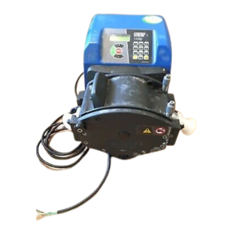
Watson-Marlow 720UN and 720SN User Manual
WATSON-MARLOW BREDEL MANUALS
m-720un-sn-gb-02
Watson-Marlow 720UN and 720SN pumps
Contents
1
Declaration of conformity
2
Declaration of incorporation
3
Five-year warranty
4
When you unpack your pump
5
Information for returning pumps
6
Peristaltic pumps: an overview
7
Safety notes
8
Pump specifications
8.1
Dimensions
9
Good pump installation practice 16
9.1
General recommendations 16
9.2
Do's and do not's
10 Connecting this product to a
power supply
11 Start-up check list
12 Switching the pump on for the
first time
13 Switching the pump on in
subsequent power cycles
(if not in auto-restart mode)
14 Manual operation
14.1 Keypad functions 720UN
14.2 Keypad functions 720SN
14.3 Speed
14.4 Direction
14.5 Keypad lock
14.6 Keypad beep
14.7 To reset defaults
14.8 To reset language
14.9 Backlight
14.10 Auto-restart
14.11 Manual operation and
remote digital inputs
and outputs
15 Main menu
15.1 Keypad functions in
menu screens
15.2 Main menu entry
16 Setup
16.1 Trim
16.2 Analogue
16.2.1 Input speed
16.2.2 Trim
16.2.3 Menu
16.3 Display
16.4 Outputs
3
16.5 Remote stop
3
16.6 Auto-restart
4
16.7 Set maximum allowed
5
speed
6
16.8 Set minimum allowed
7
speed
8
16.9 Scrolling
10
16.10 Date and time
16.11 Backlight
15
16.12 ROM
16.13 Language
17
16.14 Defaults
16.15 Security code
18
16.16 Exit
17 MemoDose and calibration
19
17.1 Changing dosing speed
17.2 Footswitch operation and
20
other remote inputs and
outputs with MemoDose
22
17.3 Flow calibration
17.4 Exit
23
23
18 Exit
19 Automatic control wiring
26
29
using the 720N module
19.1 720N module removal and
29
29
replacement
19.2 Wiring up
30
30
19.3 Speed: analogue input
19.4 Speed: analogue output
30
30
19.5 Tachometer frequency
output
31
19.6 Run/stop input
19.7 Direction input
31
19.8 Auto / manual toggle
input
32
19.9 MemoDose input
19.10 Leak detection input
32
32
19.11 Outputs 1, 2, 3, 4
19.12 Supply voltages
34
35
20 Automatic control and operation 65
21 Troubleshooting
36
37
21.1 Error codes
22 Drive maintenance
38
38
23 Drive spares
24 720R, 720RX, 720RE and
39
40
720REX pumpheads installation 68
42
44
45
45
46
46
47
47
48
48
49
50
51
52
53
53
54
54
55
55
56
59
60
60
61
61
62
62
62
63
63
66
67
68
68
1
Advertisement

Related Manuals for Watson-Marlow 720UN


Summary of Contents for Watson-Marlow 720UN
- Page 1 20 Automatic control and operation 65 21 Troubleshooting 16.2 Analogue 16.2.1 Input speed 21.1 Error codes 22 Drive maintenance 16.2.2 Trim 16.2.3 Menu 23 Drive spares 24 720R, 720RX, 720RE and 16.3 Display 16.4 Outputs 720REX pumpheads installation 68 Watson-Marlow 720UN and 720SN User Manual...
- Page 2 26.1 720R and 720RX continuous tube loading 26.2 720RE and 720REX LoadSure element loading 74 27 Pumphead spares: continuous tubing models 720R and 720RX 75 28 Pumphead spares: LoadSure element models 720RE and 720REX Watson-Marlow 720UN and 720SN User Manual...
- Page 3 1 Declaration of conformity UN, SN This declaration was issued for Watson-Marlow 720UN and 720SN pumps on May 1, 2007. When this pump unit is used as a stand-alone pump it complies with: Machinery Directive 2006/42/EC, Directive 2004/108/EC. This pump is ETL listed: ETL control number 3050250. Cert to CAN/CSA std C22.2 No 61010-1.
- Page 4 Watson-Marlow shall not be liable for any loss, damage, or expense directly or indi- rectly related to or arising out of the use of its products, including damage or injury...
- Page 5 Check that all components are present. Inspect components for damage in transit. If anything is missing or damaged, contact your distributor immediately. Components supplied 720UN and 720SN pumps are supplied as: Dedicated 720 pump drive unit fitted with 720R, 720RE, 720RX or 720REX pumpheads (see 8. Pump specifications).
- Page 6 Equipment which has been contaminated with, or exposed to, body fluids, toxic chem- icals or any other substance hazardous to health must be decontaminated before it is returned to Watson-Marlow or its distributor. A certificate included at the rear of these operating instructions, or signed statement, must be attached to the outside of the shipping carton.
- Page 7 Peristaltic pumps operate on the positive displacement principle. They are particularly suitable for metering, dosing and dispensing applications. Pumps are easy to install, simple to operate and inexpensive to maintain. Watson-Marlow 720UN and 720SN User Manual...
- Page 8 If the pump is used in a manner not spec- ified by Watson-Marlow Limited, the protection provided by the pump may be impaired.
- Page 9 Do not fit any devices to the drive unit other than those tested and approved by Watson-Marlow. Doing so could lead to injury to persons or damage to property for which no liability can be accepted.
- Page 10 Labels fixed to the rear of the pump contain manufacturer and contact details, product reference number, serial number and model details. The same information is carried on the drive’s backplate, accessible when the 720N module is removed. The number of connectors varies according to the model. Watson-Marlow 720UN and 720SN User Manual...
- Page 11 Guard switch Primary operator protection from rotating parts of the pump is provided by the pumphead track. Secondary operator protection from rotating parts of the pump is provided by indicator-only switching of the pumphead track. Watson-Marlow 720UN and 720SN User Manual...
- Page 12 * 720N cased pumps are rated to NEMA 4X (indoor use) only. Unit weight Drive only + 720R, 720RE + 720RX, 720REX IP66 NEMA 4X 18.5kg, 40lb 13oz 25kg, 55lb 2oz 31.5kg, 69lb 7oz Watson-Marlow 720UN and 720SN User Manual...
- Page 13 10% - 100% RH Weight See table on previous page Noise <85dB(A) at 1m Max peak pressure rating † 2 bar (30 psi) * Protect from prolonged UV exposure. † For all tube materials including STA-PURE. Watson-Marlow 720UN and 720SN User Manual...
- Page 14 BS EN 809 UL 61010A-1 CAN/CSA-C22.2 No 61010-1 Other Conducted emissions FCC 47CFR, Part 15.107 standards Radiated emissions FCC 47CFR, Part 15 NEMA 4X to NEMA 250 (indoor use) for IP66 products only Watson-Marlow 720UN and 720SN User Manual...
- Page 15 164mm 186mm 65mm 346mm 508mm 150mm 658mm 305mm 160mm 61mm 221mm 280mm Unit weights Drive only + 720R, 720RE + 720RX, 720REX IP66 NEMA 4X 18.5kg, 40lb 13oz 25kg, 55lb 2oz 31.5kg, 69lb 7oz Watson-Marlow 720UN and 720SN User Manual...
- Page 16 (2ft) of the connecting pipework rises as it approaches the pumphead on both the inlet and discharge sides. This helps the sliders which hold the element in place to find their optimum position. Failure to do this may result in premature element failure. Watson-Marlow 720UN and 720SN User Manual...
- Page 17 When using Marprene or Bioprene continuous tubing, do re-tension the tube after the first 30 minutes of running. Tube selection: The chemical compatibility lists published in Watson-Marlow publi- cations are guides. If in doubt about the compatibility of a tube material and the duty fluid, request a Watson-Marlow tube sample card for immersion trials.
- Page 18 IP66 specification pumps are supplied with no plug. Wiring a mains plug must only be undertaken by suitably skilled, qualified personnel. Conductor coding European North American line brown black neutral blue white ground green/yellow green Watson-Marlow 720UN and 720SN User Manual...
- Page 19 See 19.1 720N module removal and replacement. If the mains power cable is inappropriate for your installation, it can be changed. Please contact your local Watson-Marlow Bredel service centre. Input line fusing: type T5A H 250V 20mm time-delayed cartridge fuse, lo- cated in a fuseholder in the centre of the switchplate at the rear of the pump.
- Page 20 (Language can be reset as described later. See 16.13 Language.) The pump displays the Watson-Marlow start-up screen for four seconds, followed by a warning screen for four seconds (an example is shown here), and then the manual mode main screen.
- Page 21 720R 25.4mm tube Scrolling increment 0.1rpm Backlight The pump is now ready to operate according to the defaults listed above. UN, SN All operating parameters may be changed by means of key-presses. See 14 Manual operation. Watson-Marlow 720UN and 720SN User Manual...
- Page 22 If a fault is found, an error message is displayed. See 21.1 Error codes. The pump displays the Watson-Marlow start-up screen for four seconds followed bya warning screen for four seconds (an example is shown here), and then the manual mode main screen.
- Page 23 When released, the pump returns to its previous status. Note: Priming can be achieved by pressing the MAX key until fluid flows through the pump and reaches the point of discharge, and then releasing the MAX key. Watson-Marlow 720UN and 720SN User Manual...
- Page 24 See START, above. MENU: causes the main menu to be displayed, from which all aspects of pump setup can be controlled, including the MemoDose facility. See 15. Main menu. Watson-Marlow 720UN and 720SN User Manual...
- Page 25 Only the START and STOP keys are active when keypad lock is on. The padlock icon is displayed. STOP STOP within half a second: shortcut entry to the MemoDose menu; when in MemoDose, shortcut return to manual mode main screen. See 17. MemoDose. Watson-Marlow 720UN and 720SN User Manual...
- Page 26 The pump will return to this speed and direction when the START key is pressed again. STOP is also used in the MemoDose facility, while calibrating the pump, and set- ting the maximum speed. Watson-Marlow 720UN and 720SN User Manual...
- Page 27 See START, above. MENU: causes the main menu to be displayed, from which pump Setup and MemoDose can be controlled. See 15. Main menu. MEMODOSE: causes the MemoDose facility to be displayed. See 17. MemoDose. Watson-Marlow 720UN and 720SN User Manual...
- Page 28 Only the START and STOP keys are active when keypad lock is on. The padlock icon is displayed. STOP STOP within half a second: shortcut entry to the MemoDose menu; when in MemoDose, shortcut return to manual mode main screen. See 17. MemoDose. Watson-Marlow 720UN and 720SN User Manual...
- Page 29 To unlock the keypad while the pump is running hold down the START key for two seconds. The padlock symbol is removed. If the pump is stopped hold down the STOP key until the padlock symbol is removed. Watson-Marlow 720UN and 720SN User Manual...
- Page 30 (see 14.7 To reset defaults). 14.9 Backlight To turn the display backlight on: Depress the STOP and UP keys together. To turn the display backlight off: Depress the STOP and DOWN keys together. See 16.11 Backlight. Watson-Marlow 720UN and 720SN User Manual...
- Page 31 (J4), to be able to start the pump from the keypad. See 19.6 Run/stop input. If STOP is pressed the remote run/stop switch will have no effect. You cannot invert the polarity of the remote direction signal. Watson-Marlow 720UN and 720SN User Manual...
- Page 32 Scrolling, Date/time, Backlight, ROM, Language, Defaults, Security code and Exit. MemoDose The MemoDose facility is used to remember the number of revolutions needed to dispense a previously dispensed volume of fluid, and cause the pump to dispense that volume repeatedly. Watson-Marlow 720UN and 720SN User Manual...
- Page 33 Pin out details Pin out information is not relevant to the 720UN IP66/NEMA 4X pumps. Selecting Pin out details causes the pump to display a warning screen and redisplay the main menu. Exit If Exit is selected, the pump returns to its last manual state with the pump stopped.
- Page 34 Follow the reverse procedure using the UP key to move to an item on a previous screen of the menu. Make a selection using the UP or DOWN keys and press ENTER to confirm your choice. Watson-Marlow 720UN and 720SN User Manual...
- Page 35 Note: By applying the maximum process control signal when the minimum is re- quested and vice versa, inverted responses can be set up. Note: Resetting factory defaults clears the trim calibration values. Watson-Marlow 720UN and 720SN User Manual...
- Page 36 See 16.2.1 Input speed. Trim displays the Trim menu, described above. See 16.1 Trim. Menu returns the user to the first section of the Setup menu. See 16 Setup. Watson-Marlow 720UN and 720SN User Manual...
- Page 37 Example values are shown here. Alternatively the user can select Program to configure the pump to respond in a user-programmed way to any process signal range within within 4-20mA, 0- 10V or 1-5V. Watson-Marlow 720UN and 720SN User Manual...
- Page 38 16.2.3 Menu Menu returns the user to the first section of the Setup menu, described above. See 16 Setup. Watson-Marlow 720UN and 720SN User Manual...
- Page 39 4 seconds before the flowrate screen appears. The warn- ing does not appear if the display formats are cycled again, unless the pump has been switched off. The pump redisplays the first screen of the Setup menu. Watson-Marlow 720UN and 720SN User Manual...
- Page 40 4. Connect to the normally open or normally closed contacts of the relay as required and configure the pump’s software accordingly. See below in this section. Note: The maximum rating on the relay contacts of this pump is 30VDC; maximum load 30W. Watson-Marlow 720UN and 720SN User Manual...
- Page 41 If STOP is pressed during configuration, the previous setting for the output is retained and the pump redisplays the Output selection screen. If Exit is chosen, the pump returns the user to the third screen of the Setup menu. Watson-Marlow 720UN and 720SN User Manual...
- Page 42 Open=stop or Open=run. Choose using the UP and DOWN keys and press ENTER to confirm. The pump briefly displays a confirmation screen and returns the user to the first screen of the Setup menu. Watson-Marlow 720UN and 720SN User Manual...
- Page 43 To toggle the sense of the remote run/stop control between open=stop and open=run: stop the pump. Turn off the mains power switch at the rear of the pump. Hold down the STOP key and the DIRECTION key, and turn on the mains power switch. Watson-Marlow 720UN and 720SN User Manual...
- Page 44 STOP key and turn the mains power switch on. The ! symbol does not appear. Do not use auto-restart for more than 100 starts per hour. We recommend remote control where a high number of starts is required. Watson-Marlow 720UN and 720SN User Manual...
- Page 45 The pump returns the user to the second screen of the Setup menu. Note: Minimum allowed speed limits speed under manual or analogue control. Note: You can reduce the speed from the minimum set speed to 0 rpm by a further press on the DOWN key. Watson-Marlow 720UN and 720SN User Manual...
- Page 46 (two digits), month (three letters), year (four digits), hour, minute and second (all two digits), pressing ENTER to confirm each one. When ENTER is pressed to confirm the seconds, the pump redisplays the third screen of the Setup menu. Watson-Marlow 720UN and 720SN User Manual...
- Page 47 This may be required if reporting pump performance to the Wat- son-Marlow service department. Alternatively ... Press DIRECTION and DOWN together to interrupt the display and show the pump’s ROM version for four seconds. Watson-Marlow 720UN and 720SN User Manual...
- Page 48 Setup screen. Switch the pump off and then on again to com- plete the defaults reset. If No was chosen, the pump makes no changes to its setup and redisplays the fourth Setup screen. Watson-Marlow 720UN and 720SN User Manual...
- Page 49 Repeat for the second digit. Repeat for the third digit. The final press on ENTER causes the pump to display a similar three-digit entry screen and the instruction "Confirm code". Repeat the digit-entry sequence. Watson-Marlow 720UN and 720SN User Manual...
- Page 50 Note: If a code has been set but forgotten, it is still possible to access the Setup screens to cancel the code or reset it to another three-digit number. Contact your supplier or Watson-Marlow Technical support for the bypass sequence. 16.16 Exit UN, SN In the fifth screen of the Setup menu Exit is highlighted.
- Page 51 Then press the STOP key twice within half a second. The pump displays the MemoDose screen. OR... 3 720UN Press the STOP key. The pump stops. Press the MENU key. Use the UP or DOWN keys to select MemoDose. Press ENTER to confirm. The pump displays the MemoDose screen.
- Page 52 Note: To retain the MemoDose value through a power interruption the pump must be in auto-restart mode. The dosing cycle will resume at the start of a dose and wait for START to be pressed, with the MemoDose percentage screen displayed. See 16.6 Auto-restart. Watson-Marlow 720UN and 720SN User Manual...
- Page 53 1 Press the STOP key twice within half a second. The pump stops and immedi- ately displays the MemoDose/Calibration screen. Use the UP or DOWN keys to select Calibration dose. Press ENTER to confirm. Watson-Marlow 720UN and 720SN User Manual...
- Page 54 Calibration dose. Press ENTER to confirm. OR... 3 720UN Press the STOP key. The pump stops. Press the MENU key. Use the UP or DOWN keys to select MemoDose. Press ENTER to confirm. The pump displays the MemoDose/Calibration screen. Use the UP or DOWN keys to select Calibration dose.
- Page 55 If necessary, remove the module’s earth link from the back of the drive. However, the link is long enough to allow the module to fold back to give access to the circuit board inside and to the back of the drive. Watson-Marlow 720UN and 720SN User Manual...
- Page 56 USA = 26AWG - 14AWG solid and 26AWG - 16AWG stranded. Cable: cir- cular. Max/min outside diameter to ensure a seal when passed through the standard gland: 9.5mm-5mm. The cable section must be circular to ensure a seal. Watson-Marlow 720UN and 720SN User Manual...
- Page 57 Screw in one of the supplied M16x1.5 cable glands in place of the plug, using the new nylon sealing washer supplied. Tighten the gland to 2.5Nm to ensure a seal, using a 21mm spanner. If a different gland is used, it must be watertight to IP66. Watson-Marlow 720UN and 720SN User Manual...
- Page 58 Permanent damage, not covered by warranty, may result. The maximum rating on the relay contacts of this pump is 30V DC; maximum load 30W. Note: Also suitable for low power: ie, 1mA at 5VDC minimum. Watson-Marlow 720UN and 720SN User Manual...
- Page 59 When using a remote potentiometer, it is important to set the analogue input to volt- age in the Setup menu. Otherwise the reference voltage supply from the Rem-pot connector will be overloaded and will not provide a full 5V or 10V. Watson-Marlow 720UN and 720SN User Manual...
- Page 60 This output has the required strength to be effective up to 3m from the pump. Longer cable runs require signal amplification. Watson-Marlow 720UN and 720SN User Manual...
- Page 61 0V terminal of the Direction i/p con- nector (J2). Low input for clockwise rotation, high input for counter-clockwise rota- tion. With no connection the pump defaults to clockwise rotation. Watson-Marlow 720UN and 720SN User Manual...
- Page 62 J9 0V terminal Yellow J9 i/p terminal J9 +12V terminal Terminate the screen in the 720N module with a 360° EMC gland if required. See 19.2 Wiring up. Note: Use only Watson-Marlow 720 series leak detectors. Watson-Marlow 720UN and 720SN User Manual...
- Page 63 In addition, supplies may be drawn from the Spare supplies connector (J12). In the table below, “Max load” is the maximum total load on each supply, irrespective of the number of connections. Watson-Marlow 720UN and 720SN User Manual...
- Page 64 Part voltage supply (+12V also -12V 10mA needed) for the Watson-Marlow proximity switch. Reference voltage for remote po- +10V tentiometer speed control. Do not (from J7) use as a general supply voltage. Note: All DC supplies are stabilised. Watson-Marlow 720UN and 720SN User Manual...
- Page 65 Press the AUTO/MAN key or make the remote auto / manual input go low (0V). The pump returns to manual operation and retains the set speed and run status from its previous operation in analogue mode. Watson-Marlow 720UN and 720SN User Manual...
- Page 66 Check direction of rotation. Check that the rotor is not slipping on the drive shaft. If trouble persists, technical assistance for this product is available from your distributor, or Watson-Marlow Ltd, Falmouth TR11 4RU, United Kingdom. Watson-Marlow 720UN and 720SN User Manual...
- Page 67 Turn OFF. Check network and connections. Or seek support tected RS485/RS232 Turn OFF. Check network and connections. Or seek support fault RS485/RS232 Turn OFF. Check network and connections. Or seek support lost General error Turn OFF. Seek support condition Watson-Marlow 720UN and 720SN User Manual...
- Page 68 Do keep the pumphead rollers and track clean and free of grease. If unsure of an installation please contact your local Watson-Marlow Technical Sup- port Office for further assistance. Watson-Marlow 720UN and 720SN User Manual...
- Page 69 10mm A/F Allen key to facilitate draining. It has an M12 blanking plug on the outer face of the foot, which can be used as a drain if a leak detector is fitted, to allow the fluid level to trigger the switch. Watson-Marlow 720UN and 720SN User Manual...
- Page 70 M8 x 16mm socket head cap screws at the top left and top right. Tighten all four in sequence. Reposition the track and the track securing bolt. Watson-Marlow 720UN and 720SN User Manual...
- Page 71 Position the track securing bolt. Note: When a second pumphead is fitted the maximum pressure for each channel should not exceed 1 bar (14.5 psi). Watson-Marlow 720UN and 720SN User Manual...
- Page 72 26 Tube loading UN, SN 720 pumps can be operated with a 720R continuous tubing pumphead or with a 720RE pumphead fitted with Watson-Marlow LoadSure tube elements. For both pumphead types, extension "X" pumphead options are available. 26.1 720R and 720RX...
- Page 73 This is necessary to counteract the normal stretch- ing that occurs with Marprene which can go unnoticed and result in poor tube life. Watson-Marlow 720UN and 720SN User Manual...
- Page 74 Tighten both the track-compression spring knobs to a torque of 3Nm (2.2 lb-ft) using a 10mm A/F spanner. Connect both ends of the element to the rest of the system using industrial- standard cam and groove connectors. Watson-Marlow 720UN and 720SN User Manual...
- Page 75 M8 x 16mm screw MR662T Stud ~ Set to 61mm MRA3063A Track assembly CN0228 M25 blanking plug MR0882M Eccentric bush MR3041T M8 x 307mm bolt ~ 720RX MR3040T M8 x 157mm bolt ~ 720R Watson-Marlow 720UN and 720SN User Manual...
- Page 76 M8 x 16mm screw MR662T Stud ~ Set to 61mm MRA3064A Track assembly CN0228 M25 blanking plug MR0882M Eccentric bush MR3041T M8 x 307mm bolt ~ 720REX MR3040T M8 x 157mm bolt ~ 720RE Watson-Marlow 720UN and 720SN User Manual...
- Page 77 29 Pumphead spares: rotor UN, SN Number Spare Description MR0879A Rotor flange MR0667T Spacer FN0420 Screw M5x16 socket countersunk MRA0039A Shaft with sun gear ~720R MR0773B Drive slot plug MRA0020A Roller assembly FN0722 Washer BB0018 15mm bearing Watson-Marlow 720UN and 720SN User Manual...
- Page 78 9.6 (720R) 12.7 15.9 25.4 bore (720R) 193 (720R) litre/hour 1100 1500 2000 USGPM Note: these figures refer to the performance of a single pumphead; where twin pumpheads are used, the figures should be doubled. Watson-Marlow 720UN and 720SN User Manual...
- Page 79 * 12.7mm, 15.9mm and 19.0mm elements have in Tri-clamp style connectors. 25.4mm elements have 1in Tri-clamp style connectors. † 12.7mm, 15.9mm and 19.0mm elements have in Cam-and-Groove connectors. 25.4mm elements have 1in Cam-and-Groove connectors. Watson-Marlow 720UN and 720SN User Manual...
- Page 80 25.4 920.0254.048 960.0254.048 33 Trademarks UN, SN Watson-Marlow, Bioprene, Pumpsil and Marprene are trademarks of Watson-Marlow Limited. Fluorel is a trademark of 3M. Sta-Pure and Chem-Sure are trademarks of W.L.Gore and Associates. 34 Warning not to use pumps in UN, SN...
- Page 81 Hazardous to Health Regulations, you are required to declare the substances which have been in contact with product(s) you return to Watson-Marlow or its sub- sidiaries or distributors. Failure to do so will cause delays. Please ensure that you fax us this form and receive an RGA (Returned Goods Authorisation) before you despatch the product(s).
Need help?
Do you have a question about the 720UN and is the answer not in the manual?
Questions and answers