Table of Contents
Advertisement
Advertisement
Table of Contents

Related Manuals for Kustom Signals Golden Eagle II


Summary of Contents for Kustom Signals Golden Eagle II
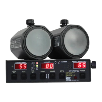
- Page 1 Golden Eagle ® Traffic Safety Radar OPERATOR’S MANUAL P/N 006-0815-10 REV. 7...
- Page 2 Kustom Signals, Inc., 9652 Loiret Blvd., Lenexa, KS 66219 Customer Service 1-800-835-0156 or (620) 431-2700...
-
Page 3: Table Of Contents
TABLE OF CONTENTS 1. INTRODUCTION............1.1 2. SPECIFICATIONS............2.1 2.0..............2.1 ENERAL 2.1............2.2 PERATIONAL 3. INSPECTION & MOUNTING ........3.1 3.0...........3.1 NITIAL NSPECTION 3.1..........3.1 ATERIALS UPPLIED 3.2..........3.2 QUIPMENT OUNTING 4. UNIT DESCRIPTION.............4.1 4.0............4.1 RONT ANEL 4.1........4.4 ROCESSING ANEL 4.2. - Page 4 7.5............7.15 TOPWATCH 7.6......7.17 PEEDOMETER ULSE PERATION 7.7.........7.18 MART ATROL EARCH 7.8...7.19 ETTING NTERFERENCE ILTER 7.9..........7.19 AINTENANCE 8. INTERFERENCE............8.1 8.0..............8.1 VERVIEW 8.1..........8.1 ATURAL NFLUENCES 8.2..........8.2 NFLUENCES 8.3............8.4 ROUNDSPEED 9. RECOMMENDED CARE & MAINTENANCE ..9.1 9.0.
-
Page 5: Introduction
To add to the flexibility of the units, Golden Eagle II radar are available in either K-Band or Ka-Band frequencies, single channel or the latest Dual Channel Microwave (DCM) antennas. -
Page 6: Specifications
Section 2—Specifications 2. SPECIFICATIONS 2.0. General Type: Two piece, Moving/Stationary, True Doppler radar system. 24.150 GHz + .1 GHz (K-band) Frequency: 33.4 to 36 GHz + .1 GHz (Ka- Band.) Tuning Forks: Forks stamped with “KSI Ka- Band” are for units with micro- wave frequency 35.5 GHz. -
Page 7: Operational
Section 2—Specifications Electronic Components: 100% solid state; integrated circuits, microprocessors and transistors tested for reliability. Operating Temperature: -22F to +140F -30C to +60C 90% relative humidity at 37°C, non-condensing. Dimensions: Processing Unit Height: 1.08" (2.74 cm) Width: 6.50" (16.51 cm) w/o mtg. knobs Depth: 3.75"... - Page 8 Section 2—Specifications Lock Time: Instantaneous. Patrol Window: Displays patrol speed in radar mode and distance in stopwatch mode. Target Window: Displays truncated target speed in radar and stopwatch modes. Lock Window: Displays locked target speed or fastest speed (Fastest Mode). Elapsed Time (stopwatch mode).
- Page 9 Section 2—Specifications Patrol: Selectable 10 or 20 to 99 MPH (16 or 32 to 159 km/h) Typical patrol speeds to 149 MPH (239 km/h). Target: Minimum: 10 MPH, 20MPH if Opposite Direction: patrol is greater than 40 MPH. Maximum target speed is function of combined patrol and target speeds to 199 MPH (320 km/h).
- Page 10 Section 2—Specifications Hold: "HLd" is displayed in TARGET window when system is not transmitting. Controlled by remote or front panel switch. FASTEST: Indicator lights when operator selects fastest mode. Flashes when fastest target is tracked and when fastest has been locked. SLOWER: During same direction operations the indicator lights when the...
- Page 11 Section 2—Specifications Antenna: Height K-band 3.25" (8.26 cm) Ka-Band (ALL) 2.52" (6.4 cm) Width K-band 7.3" (18.54 cm) Ka-Band (ALL) 2.52" (6.4 cm) Depth K-band 3.6" (9.14 cm) Ka-Band 3.2" (8.13 cm) Ka-DCM 3.75" (9.5 cm) Weight K-band 1.88 lbs (0.85 kg) Ka-Band 0.7 lbs (0.32 kg) Ka-DCM...
-
Page 12: Inspection & Mounting
Section 3—Inspection & Mounting 3. INSPECTION & MOUNTING 3.0. Initial Inspection Before installing your Golden Eagle II, please take a moment to carefully inspect it for damage caused by shipping. Contact the shipping carrier at once if you notice any damage. -
Page 13: Equipment Mounting
An auxiliary power receptacle, which mounts under the dashboard and wires directly to the battery, is available for the Golden Eagle II radar system. 1. Mount the receptacle in the desired location using the hardware provided. - Page 14 The Golden Eagle II display panel can be located overhead, on the dashboard or on the radio rack. The logic unit can be located under the dash, in the glove box or under the front seat.
- Page 15 See Sec. 3.2.0. 4. Momentarily depress the POWER switch on the front panel of the Golden Eagle II (refer to Section 4.0 for location and function of front panel switches). It will process through a lamp test and internal test as described later in Section 6.
- Page 16 Section 3—Inspection & Mounting 5. Select the unsquelched (audio on) mode by momentarily depressing the AUDIO then the MODE switch. If necessary, depress the AUDIO switch then the RANGE (up) switch to increase the audio level. 6. Start the patrol vehicle and position the A/C - heater fan to a mid-range speed.
- Page 17 Section 3—Inspection & Mounting NOTE: The advanced Digital Signal Processing in the Golden Eagle II can reduce the problems of fan noise. If, after mounting your antennas, there are still problems with fan interference in your type of patrol vehicle, Kustom Signals can provide antenna noise reduction pads to prevent the fan signal from reaching the antennas.
- Page 18 1. Place the antenna on the rear-mounting bracket. 2. Follow the procedure for determining any fan interference per Section 3.2.2, steps 4-6. Set the Golden Eagle II for stationary mode, rear antenna. Stationary Mode Rear Antenna 3. After the optimum position has been located (and marked per 3.2.2 step 6), permanently attach the mount...
- Page 19 3.2.4. Speedometer Pulse Cable Installation Installing the provided cable to the vehicle’s speed sensor (VSS) provides a signal to the Golden Eagle II for Kustom Signals patented Tru-Trak assisted patrol speed search feature. This feature virtually eliminates the problems of patrol shadowing and patrol combining.
-
Page 20: Unit Description
MODE AUDIO RANGE HOLD POWER GOLDEN EAGLE II KUSTOM SIGNALS, INC. A. TARGET SPEED Displays the strongest target Window speed in either stationary or moving mode. If a fastest target is Locked, this window will track the fastest speed. In stopwatch mode the window displays calculated target speed. - Page 21 Section 4—Unit Description E. LOCK/RELEASE Switch used to lock and unlock Switch target and patrol vehicle speeds. In the stopwatch mode, used to start, stop and clear the timing cycle. F. TEST Switch Switch used to activate the displays, test the internal accuracy and enter the tuning fork test mode.
- Page 22 Section 4—Unit Description M. Ambient Light Detects ambient light conditions Detector and adjusts the brightness of displays automatically. N. HOLD Switch This switch used to turn the selected antenna’s microwave transmitter on and off. O. POWER Switch System power control – on/off. P.
-
Page 23: Processing Unit Rear Panel
Processing Unit Rear Panel REMOTE PORT 1 SPDOMTR The rear panel of the Golden Eagle II has connectors for the remote control, speedometer input, RS232 I/O port and two antennas. In addition, there is a captive power cord attached to the rear panel. -
Page 24: Remote Control
4.2. Remote Control FRNT LOCK HOLD FAST REAR SLOW HOLD SAME GOLDEN EAGLE II KUSTOM SIGNALS, INC. The remote control is available in either a wired or wireless version. - Page 25 Section 4—Unit Description A. LOCK-RELEASE This switch is used for locking (Start-Stop-Clear and releasing target and patrol in stopwatch mode) speeds. In the stopwatch mode will start, stop and clear the timer. B. FRONT HOLD This switch used to turn the front antenna microwave transmitter on and off.
- Page 26 Golden Eagle II in a default mode. 1. Power the Golden Eagle II off. 2. Depress and HOLD the power switch. During the power-on test sequence the unit will display the lamp test, internal test, and audio (Aud) and range (rnG) levels.
- Page 27 5. The rear antenna, fastest/slower and same direction features will not be accessible without a remote control. 6. The Golden Eagle II will restore remote control access automatically upon receiving the first remote control command.
-
Page 28: General Theory Of Operation
5. GENERAL THEORY OF OPERATION 5.0. General Theory The Golden Eagle II moving radar system transmits a radio frequency on either K-Band, or Ka-Band, in compliance with the Federal Communications Commission (FCC) regulations. In moving mode a portion of the transmitted signal reflects from the surface of passing stationary objects back to the antenna. - Page 29 DSP. The Difference Doppler is the speed difference between the patrol vehicle and a vehicle traveling in the same direction. If the Golden Eagle II is equipped with DCM antennas, it is capable of automatically determining if the target vehicle is traveling faster or slower than the patrol vehicle.
-
Page 30: Microwave Rf Emissions
Section 5--General Theory of Operation 5.1. Microwave RF Emissions Traffic radar operators may have some questions about the biological effects of exposure to the microwave energy produced by the radar devices. According to all credible evidence, the emission levels resulting from traffic radar use pose no threat whatsoever, either to the radar operator or to target vehicle occupants. - Page 31 For a free copy of the latest information regarding the safe human exposure standards, please call or write Kustom to request the "RF Emissions Packet." You may contact us at our corporate headquarters: Kustom Signals, Inc. 9652 Loiret Blvd. Lenexa, KS 66219 (913)492-1400 While traffic radar devices do emit microwave energy, the levels are so low that there are no probable harmful effects.
-
Page 32: Testing Procedures
Section 6--Testing Procedures 6. TESTING PROCEDURES 6.0. Overview The tuning fork tests explained below should be conducted at the beginning and end of each patrol shift to ensure the accuracy and functionality of the unit. The results of these tests may be recorded in a radar log, similar to the log found at the end of this manual. -
Page 33: Antenna Test
The operator can depress the TEST switch at any time during normal radar operation to perform the display and internal tests. If the Golden Eagle II is in the stopwatch mode and a timing cycle is in process, the test switch is inoperative until the timing cycle has ended. -
Page 34: Tuning Fork Testing
(See Sec. 6.5). 6.5. Tuning Fork Testing Supplied with the Golden Eagle II are two tuning forks, 35 MPH and 65 MPH (45 km/h and 80 km/h) for K and some Ka-Band, 30 and 55 MPH for other Ka-Band. These tuning forks will simulate vehicles in the stationary or moving modes. - Page 35 1. If the unit is displaying "Hld" in the TARGET window, depress the FRNT/HOLD or REAR/HOLD switch to select the antenna to be tested. If necessary press the MODE switch to place the Golden Eagle II in the stationary mode (both direction antenna/mode indicators should be on).
- Page 36 Depress the LOCK/REL switch a second time and the LOCK window should be cleared. 8. Depress the MODE switch to place the Golden Eagle II in the moving mode, opposite direction, front antenna. Only the patrol LED and the front, opposite direction LED indicator will be lit.
- Page 37 (30), equals target speed (25). 6.5.1. Same Direction Tuning Fork Test 1. With the Golden Eagle II in the moving mode, use the FRNT/HOLD or REAR/HOLD switch to select the proper antenna, depress the SAME/OPP switch to place the unit in the Same-Direction mode.
- Page 38 NOTE: Do not move the tuning forks after they have been placed in front of the antenna. 3. Ensure that the Golden Eagle II is not in the HOLD mode and that the RANGE control is set to 6 (maximum range).
-
Page 39: Moving Mode Test
6.6. Moving Mode Test Verification of speed readings between the patrol vehicle's speedometer and the Golden Eagle II's Patrol Speed window is another accuracy test that can be performed. These readings should be the same, or within reasonable limits, allowing for minor speedometer error. -
Page 40: Speedometer Input Synchronization
Section 6--Testing Procedures 6.7. Speedometer Input Synchronization The initial use of the Golden Eagle II with speedometer pulse input requires the radar unit to be synchronized with the speedometer. 1. After installation and initial testing with tuning forks, the Golden Eagle II should be driven at a constant speed between 30 and 70 MPH (48 and 112 km/h). - Page 41 PATROL window and no target speeds will be displayed. 4. A Golden Eagle II equipped with speedometer input will automatically control moving/stationary mode switching. When the patrol vehicle comes to a stop the unit will automatically switch to stationary mode.
-
Page 42: System Operation
Section 7--System Operation 7. SYSTEM OPERATION 7.0. Operating Modes The Golden Eagle II is designed to be a versatile radar system developed for law enforcement use. It has 7 different operating modes: 1. Stationary Front Antenna 2. Stationary Rear Antenna 3. -
Page 43: Setup
Section 7--System Operation 7.1. Setup 1. Select a location that provides a good view of the traffic to be monitored. 2. Check the immediate area for potential interference sources, such as large reflecting signs in the direct path of the radar's microwave beam, power substations and other sources of electrical interference. - Page 44 RANGE switch and the TARGET window will display "rnG" and the PATROL window will display the current level (1 - 6). Range level 6 is maximum range; range level 1 reduces the Golden Eagle II's range to its minimum distance. Depressing the DOWN (AUDIO) or UP (RANGE) switches will decrease or increase the range level.
- Page 45 NOTE: The advanced Digital Signal Processing in the Golden Eagle II can reduce the problems of fan noise. If there are still problems with fan interference in your type of patrol vehicle, Kustom...
-
Page 46: Stationary Operation
Section 7--System Operation 7.2. Stationary Operation The antennas of the Golden Eagle II are set up separately and independently. To change the mode of an antenna it must be selected with either the FRNT/HOLD or REAR/HOLD switch. 1. Select one of the antennas by pressing either the FRNT/HOLD or REAR/HOLD switch. - Page 47 LOCK window. 5. The Golden Eagle II will continue to track the violator's speed in the TARGET window as long as the vehicle is in the antenna beam.
- Page 48 The Golden Eagle II will automatically run an internal test prior to locking any speed. Depressing the TEST switch will allow the Golden Eagle II to complete a display and internal test then return the locked speed. 7. To manually unlock or clear the locked speed, depress the LOCK/REL switch.
- Page 49 NOTE: If the auto-unlock feature is enabled, the locked speed will be automatically unlocked after 14 minutes. 5. If the remote control is damaged or lost, refer to Sec. 4.2.0 for default operation of the Golden Eagle II without a remote control.
-
Page 50: Moving Operation (Opposite Direction)
There are two modes of moving operation: 1) Moving Opposite Direction. 2) Moving Same Direction. The antennas of the Golden Eagle II are set up separately and independently. In this way, if the operator chooses, the front antenna can be set to one mode (Moving Opposite Direction) and the rear antenna can be set to a different mode (Moving Same Direction). - Page 51 A short alert tone will be heard when the internal tests are complete and the LOCK window will display the speed of the target vehicle. 6. The Golden Eagle II will continue to track the target and patrol speeds. 7. When the patrol vehicle's speed decreases by 10 MPH...
- Page 52 All locked speeds will be retained. 11. If the remote control is damaged or lost, refer to Section 4.2.0 for default operation of the Golden Eagle II without a remote control. 7.11...
- Page 53 7.3.0. Fastest Vehicle--Moving Operation 1. Set up system as in Sec. 7.3, steps 1-4. 2. The Golden Eagle II allows two methods of fastest vehicle mode (Push and Hold control or Toggle control). See Sec. 13 (Options) for selecting the preferred method.
-
Page 54: Moving Operation (Same Direction)
Section 7--System Operation 7 .4. Moving Operation (Same Direction) The antennas of the Golden Eagle II are set up separately and independently. In this way, if the operator chooses, the front antenna can be set to one mode (Moving Opposite Direction) and the rear antenna can be set to a different mode (Moving Same Direction). - Page 55 Section 7--System Operation 3. If the target vehicle is traveling slower than the patrol vehicle, the operator should press and hold the SLOWER switch on the remote control. NOTE: If the unit has “DCM” antennas the radar will automatically determine if the target vehicle is traveling slower or faster.
-
Page 56: Stopwatch
The alert tones are used to verify the acceptance of the start and stop commands. 6. The Golden Eagle II will calculate the average speed of the target vehicle and display the truncated (rounded down) speed in the TARGET window. The elapsed time (rounded up to the nearest tenth second) will be displayed in the LOCK/E.T. - Page 57 Section 7--System Operation NOTE: An internal accuracy test is completed at the end of each timing cycle, before the calculated target speed is displayed. If an error is found, "Err" will be displayed in the TARGET window and no speed readings will be displayed. 7.
-
Page 58: Speedometer Pulse Operation
Section 7--System Operation 7.6. Speedometer Pulse Operation The Golden Eagle II has hardware and software in place to interface the unit to the patrol vehicles speed sensor. The speed sensors input pulses steer the DSP in the search for the Doppler patrol signal. This patented technique virtually eliminates problems of patrol shadowing and patrol combining. -
Page 59: Smart Patrol Search
Section 7--System Operation 7.7. Smart Patrol Search As stated in section 7.6 the Golden Eagle II can be operated with or without speedometer input. If the speedometer input is not connected, the unit will use patent pending Smart Patrol Search (SPS) software routines. This software... -
Page 60: Setting Fan Interference Filter Mode
7.9. Maintenance Mode The Golden Eagle II has a maintenance/configuration mode, which can be used by technicians for diagnosis and troubleshooting. Holding the POWER switch depressed for 5 seconds or longer during power up can access this mode. -
Page 61: Interference
Digital Signal Processing circuitry will eliminate most of these influences and a knowledgeable operator should be able to determine the nature of the influences and their effect, if any, on the performance of the Golden Eagle II. 8.1. Natural Influences 1. -
Page 62: Man-Made Influences
PATROL window and used instead of the proper patrol speed. See Section 8.3. NOTE: If the Golden Eagle II is displaying a low patrol speed due to shadowing, entering and exiting Hold quickly should resolve the problem. - Page 63 5. If the power supply voltage drops below the minimum operating voltage, the Golden Eagle II will not display any new speed readings until the low voltage condition is no longer exists. "Lo" will be displayed in the TARGET window.
-
Page 64: Groundspeed
HOLD mode. In most instances this tactic will also eliminate a combined speed in the PATROL window. The Golden Eagle II's DSP system will always look for and display groundspeed before displaying any targets. The groundspeed radar signature is normally unlike any target or interference signal. - Page 65 Section 8—Interference NOTE: Minimum ground speed displayed is selectable at either 10 or 20 MPH (16 or 32 km/h). To check the setting, press the PAT/SEL switch while the radar is not locked. The TARGET window will display "PAt", the PATROL window will display either "10"...
-
Page 66: Recommended Care & Maintenance
9. RECOMMENDED CARE & MAINTENANCE 9.0. Care Of The Golden Eagle II The Golden Eagle II radar system is designed for long, reliable use by law enforcement agencies. Following basic care guidelines will ensure the unit gives many years of trouble-free service. - Page 67 Receiver diode degradation has no effect on the unit's accuracy, but will result in unsatisfactory target range. 7. Kustom Signals recommends periodic maintenance of the Golden Eagle II radar system. Check with your local service center and judicial district for requirements.
-
Page 68: Case Law
Since the Golden Eagle II is a Doppler based traffic radar system, some older case law is presented because of its significance to the acceptance of the Doppler principles as well as the basic requirements of the tuning fork test and operator training. - Page 69 Section 10--Case law The court held and took judicial notice of the accuracy of Doppler radar in both the stationary and moving modes of operation. Reference E -- Samuel Knight vs. State of New York Superior Court. 72 N.Y. 2d 481, 530 N.E. 2d 1273 (1988). The court ruled that a trained operator, who properly tested the radar, observed the traffic and checked the patrol speed against the patrol vehicle's speedometer, can accurately...
-
Page 70: Fcc Licensing
Section 11--FCC Licensing 11. FCC LICENSING 11.0. FCC – Transmitter Rules Amended The Federal Communications Commission (FCC) has amended its rules to eliminate the required annual measurement of transmitter power, frequency and modulation and to specify transmitter power in terms of output power for licensees in the Public Safety, Industrial and Land Transportation Radio Services. -
Page 71: Fcc - Licensing
Section 11--FCC Licensing 11.1. FCC – Licensing The Commission has eliminated the requirement for local governmental entities licensed in the Public Safety Radio services to obtain a separate authorization for radar speed detection devices. This change reduces paperwork for the Commission's licensing staff and for police and other local government units, which no longer have to apply for new radar authorizations or modify or renew existing licenses and... -
Page 72: Troubleshooting
Section 12—Troubleshooting 12. TROUBLESHOOTING If an operating difficulty is encountered, check the following list of possible problems and solutions before returning the unit to the factory or local Service Center. Problem Possible Solution No Power Indication Check for proper voltage at cigarette plug. - Page 73 Section 12—Troubleshooting No target speeds Verify that RANGE control is set during tuning fork to 6, maximum range. test If the unit has “DCM” antennas, it must be in TEST mode to read tuning forks. Test mode can be selected by pressing the TEST button and is indicated by the Test indicator flashing.
- Page 74 Section 12—Troubleshooting No patrol speed Verify that the unit is NOT in the during tuning HOLD mode. fork test If the unit has “DCM” antennas, it must be in Test mode to read tuning forks. Test mode can be selected by pressing the TEST switch and is indicated by the Test indicator flashing.
- Page 75 Section 12—Troubleshooting No target readings Unsquelch the audio and verify that a in stationary mode Doppler tone is heard when targets (cont). are present. If no Doppler tone is heard, change antennas or remove unit from service. Refer to fan interference in Sec. 8.2. Remove unit from service if above tests fail.
- Page 76 Section 12—Troubleshooting No patrol speed (unit If speedometer input is used: not in lock) (cont) Verify unit is synchronized to atrol vehicle (see 6.7). Verify patrol speed is above 10 PH (16 km/h). Verify antenna is aimed properly and is not obstructed. Remove unit from service if above tests fail.
- Page 77 Section 12—Troubleshooting No target readings in Verify that the unit is NOT in the moving mode HOLD mode. Verify the range control is set properly. Verify the desired antenna is selected. Verify the proper patrol speed is being displayed. Verify moving mode is selected. Target speed may be harmonic (same as) patrol speed.
- Page 78 Section 12—Troubleshooting Short range Verify the range control setting. Verify the desired antenna is selected. Verify the antenna is properly aimed. Verify the unit is not in the HOLD mode. Verify there are no obstructions between the antenna and the target.
- Page 79 Section 12—Troubleshooting Intermittent Sometimes caused by multiple Readings targets traveling at or near the same speed. Verify the range control setting. Target vehicle may be out of range of radar. Verify there are no obstructions between the radar and the target. Moving mode - verify proper patrol speed is being displayed.
-
Page 80: Options
Section 13—Options 13. OPTIONS 13.0. OPTIONS SETUP The Golden Eagle II allows the operator to change certain operating parameters of the unit. The following is a list of the available parameters. Each has a number after the option. An example will be given to instruct the operator how to change the unit. -
Page 81: Options Descriptions
Auto-Alarm; add 2 for Auto-Lock. 13.1.2. STANDARD OR ALTERNATE SERIAL OUTPUT The Golden Eagle II defaults to allow the standard serial outputs. If one of the special alternate outputs is required, add 8 to the Options total. 13.1.3. FASTEST OPERATION The Golden Eagle II offers two modes of fastest operation. - Page 82 Section 13—Options 13.1.4. INTERFACE OUTPUT PROTOCOL The Golden Eagle II defaults to allow the radar unit to ® interface with the KSI Eyewitness video equipment. Contact Kustom's Customer Service Department at (800)- 835-0156 or (620) 431-2700 for other video or other third party equipment output protocol options.
-
Page 83: Options Examples
Section 13—Options 13.2. OPTIONS EXAMPLES Using the above options list, add all the numbers for the options you want active. NOTE: default options, such as MPH and Standard output, have a value of zero (0). To enter the Options Menu mode, power the unit off, then press and hold the POWER switch until the power-on sequence stops. -
Page 84: Attestation Of Conformity
Section 14—Attestation of Conformity 14. ATTESTATION OF CONFORMITY 14.0. CE Certification of Conformity 14.1... -
Page 85: As/Nz Certification Of Conformity
Section 14—Attestation of Conformity 14.1. AS/NZ Certification of Conformity 14.2... - Page 86 For additional mounting suggestions, please contact the Kustom Signals Customer Service Department. Kustom Signals cannot accept any liability for equipment, which has been mounted in conflict with the vehicle manufacturer's recommendation for proper airbag deployment.
- Page 87 _____________ UNIT SERIAL NUMBER ON DUTY TEST OFF DUTY TEST FORK/ DRIVE/ FORK/ DRIVE/ DATE TEST SIGN TEST SIGN COMMENTS READ RADAR READ RADAR...
Need help?
Do you have a question about the Golden Eagle II and is the answer not in the manual?
Questions and answers