
Related Manuals for Kustom Signals Falcon HR


Summary of Contents for Kustom Signals Falcon HR
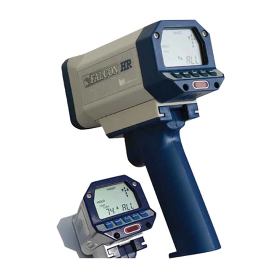
- Page 1 OPERATOR’S MANUAL P/N 006-0862-00 Rev. 0 1010 W CHESTNUT CHANUTE, KS 66720-0947...
- Page 3 This publication may not be reproduced, stored in a retrieval system, or transmitted in whole or in part in any form or by any means electronic, mechanical, photocopying, recording, or otherwise without prior written permission of Kustom Signals, Inc., 9325 Pflumm Road, Lenexa, KS 66215-3347 Customer Service 1-800-835-0156 (620-431-2700)
-
Page 5: Table Of Contents
SECTION PAGE 1. INTRODUCTION............1.1 2. SPECIFICATIONS 2.0 General..............2.1 2.1 Operational...............2.3 3. INSPECTION AND INSTALLATION 3.0 Initial Inspection ............3.1 3.1 Material Supplied.............3.1 3.2 Cable Installation .............3.2 3.3 Radar Installation ............3.4 4. UNIT DESCRIPTION 4.0 Side View..............4.1 4.1 Rear Panel..............4.2 4.2 Remote Control ............4.5 4.3 Mounting Pod (Optional) ........4.7 5. - Page 6 SECTION PAGE 6.4 Tuning Fork Testing ..........6.2 6.5 Speedometer Verification........6.7 6.6 Minimum Patrol Speed Set ........6.9 6.7 Moving Mode Test ...........6.9 7. OPERATION 7.0 Operating Modes............7.1 7.1 Operational Setup ............7.1 7.2 Operation--Handheld ..........7.5 7.3 Operation—Dash Mounted........7.7 7.4 Moving Mode—Opposite Direction .......7.9 7.5 Moving Mode—Same Direction ......7.12 7.6 Speedometer Pulse Operation........7.13 7.7 Smart Patrol Search ..........7.14...
- Page 7 SECTION PAGE 12. TROUBLESHOOTING ..........12.1 13. DIRECTIONAL OPERATIONAL SUPPLEMENT.13.1 13.0 Directional Operation..........13.1 13.1 Stationary Road Graphic ........13.2 13.2 Moving Mode Road Graphic ......13.2 13.3 Test Mode .............13.3 13.4 Stationary Operation ...........13.4 13.5 Moving Mode Operation ........13.7 13.6 Locking..............13.10 14. OPTIONS 14.0 Options Setup ............14.1 14.1 Options Description ..........14.2 14.2 Options Examples ..........14.4...
-
Page 8: Introduction
FalconHR units have the newest directional features; D ual C hannel M icrowave antenna and Directional D igital S ignal P rocessing (DSP). This allows Kustom Signals to add features such as same direction with automatic add or subtract difference speed, fastest vehicle detection in all... -
Page 9: Specifications
2. SPECIFICATIONS 2.0 GENERAL Type: One-piece, Directional Moving / Stationary, Doppler radar system. Frequency: Ka-Band 24.125 GHz +100 MHz System Accuracy: Stationary +1 mph (+2km/h) Moving +1/-2 mph (+2/-3 km/h) Operating Voltage: Corded: 10.0 to 16.5 VDC, 300 mA The FalconHR will operate normally and not display a low voltage alert to at least 10.0 VDC. - Page 10 Nominal Power Requirements: Voltage (VDC) Current (mA) No target present: 13.6 With target present: Audio = Max 13.6 Backlight = Off With target present: Audio = Max 13.6 Backlight = On Standby (HOLD): 13.6 After 30 seconds Reverse Voltage Diode protection. No damage if Protection: supply leads reversed.
-
Page 11: Operational
2.1 OPERATIONAL Speed Processor: Digital Signal Processing (DSP) performs all functions and signal analysis. Manual Test: All display segments checked; checks internal calibration and performs a cross check of quartz crystals for accuracy. Automatic self-test: Comparison of quartz crystals done periodically (5 minutes maximum), upon every mode change and at the time of lock. - Page 12 Speed Range: Meets IACP/NHTSA specifications for target sensitivity. Stationary: 10 dB from 35 to 90 mph (56 to 144 km/h); 5 dB from 60 to 90 mph (96 to 144 km/h). Moving (Opposite Dir.): 10 dB for targets from 40 to 90 mph (64 to 144 km/h);...
- Page 13 Target: Opposite Dir.: Target minimum (Patrol < 40 mph): Spec: 10 mph (16 km/h) Typical: 9mph (14 km/h) Target minimum (Patrol > 40 mph): Spec: 20 mph (32 km/h) Target maximum: (Combined patrol and target speeds): Spec: 205 mph (330 km/h) Typical: 208 mph (334 km/h).
- Page 14 Indicators: Stationary: “TARGET” window displayed. Moving: “PATROL” and “TARGET” both displayed in window. Low Battery: (Warning) Flashing “BATT” displayed and an audio warning tone sounds every 2 minutes when internal voltage falls below approximately 6.6 VDC. Approximately 30 minutes of transmitter operation remains.
- Page 15 Lock: “LOCK” displayed and flashing indicating locked target speed. Fastest: “FAST” displayed when fastest mode (stationary or moving) selected. Indicator flashes in locked fastest mode. Test: Indicator flashed when the unit is in tuning fork test mode. Km/h: Indicator is on when the unit is displaying speeds in km/h.
-
Page 16: Inspection And Installation
Remove the unit from the shipping carton and check the packing list against your original purchase order. If the shipment is incomplete or parts are missing, please contact Kustom Signals Customer Service Department at 1-800- 835-0156, or (620) 431-2700. 3.1 MATERIALS SUPPLIED... -
Page 17: Cable Installation
3.2 CABLE INSTALLATION 3.2.1 AUXILIARY POWER RECEPTACLE Cigarette lighter receptacles have been the traditional source of power for traffic radar over the years. In newer vehicles, it is possible that poor grounding of this receptacle and electrical noise from various sources can combine to create an unacceptably high level of electronic interference. - Page 18 3.2.2 SPEEDOMETER PULSE CABLE Installing the provided cable to the vehicle’s speed sensor (VSS) provides a signal to the FalconHR for Kustom Signals patented Tru-Trak assisted patrol speed search feature. This feature virtually eliminates the problems of patrol shadowing and patrol combining. This signal also allows the unit to automatically switch between moving and stationary modes as the vehicle’s movement is sensed.
-
Page 19: Radar Installation
3.3 RADAR INSTALLATION 1. The FalconHR is shipped with the handle (corded or cordless) attached. With the handle attached, the user can operate the unit in the handheld or dash mounted mode. In the handheld configuration, the radar operates only in the stationary mode when the unit is removed from the mount. - Page 20 5. Momentarily press the PWR switch on the rear panel of the FalconHR. (Refer to Section 4.1 for location and function of the switches.) The FalconHR will proceed through an indicator test, internal test and several other reliability tests. Select the Stationary “ALL” mode of operation by pressing the MODE switch, if required.
- Page 21 8. When a suitable location is found, secure the dash bracket to the windshield using the suction cups and Velcro. 9. Position of the antenna: Moving: Aim the antenna parallel to the ground and straight down the roadway. Stationary: Unit may be operated on the mount or handheld to achieve maximum performance and pointed directly toward the vehicles being monitored.
-
Page 22: Unit Description
4. UNIT DESCRIPTION 4.0 SIDE VIEW Trigger When the FalconHR is off the mount, it operates in stationary mode only. The trigger is used to : Activate the transmitter Lock the active target speed Control the optional fastest feature Data / Charger connector NOTE: The FalconHR can connect to video systems, remote control systems, or have the operating software updated through the data connector. -
Page 23: Rear Panel
4.1 REAR PANEL TARGET Km/h TEST BATT HOLD FAST SLOW LOCK PATROL TEST MODE A. TARGET Displays target vehicle speeds in stationary and moving modes. B. Km/h Indicates when the speed readings are in kilometers per hour, km/h. - Page 24 C. Road Graphic Indicates Mode of operation: moving or stationary. Indicates target direction: approaching or receding. D. PATROL Displays the patrol vehicle speed. Displays the stationary directional modes: Approaching only “APr”, Receding only, “rEc”, or All “ALL”. E. PWR Turns the unit on or off. F.
- Page 25 L. FAST/LOCK Displays fastest or locked vehicle Display speeds. M. LOCK Indicates the FAST/LOCK display is showing a Locked speed. N. FAST Indicates the unit is in fastest mode and that the fastest vehicle speed is displayed in the FAST/LOCK window.
-
Page 26: Remote Control
4.2 REMOTE CONTROL FALCON HR FALCON HR Wireless Remote Wired Remote When the FalconHR has a handle attached and is placed in the mount, certain functions can be controlled with the Wireless/Infrared (IR) remote. If the unit is attached to the... - Page 27 The remote controls the following functions: A. HOLD Turns the radar transmitter on and off. B. SAME/OPP In moving mode, selects either the same or opposite direction. In stationary mode this button toggles between approaching only and receding only modes. C.
-
Page 28: Mounting Pod (Optional)
4.3 MOUNTING POD (OPTIONAL) A. Data Port RS232 I/O port provides information to video systems or for updating operating software. All operations of the FalconHR can be controlled via this port. B. Speedometer Input Accepts speedometer cable connector. C. Remote Control Accepts the wired remote control jack. -
Page 29: General Theory Of Operation
(groundspeed) and is displayed in the PATROL window. Kustom Signals radar has a patented feature using the patrol vehicle’s speed sensor pulses, which steers the DSP processor to look for the “groundspeed” Doppler signal in a specific speed range. - Page 30 Upon receiving the "target" Doppler signal, the processing unit automatically computes the difference between the speed of the patrol vehicle and the target vehicle. The speed of the approaching vehicle registers in the TARGET window. If, for example, a patrol vehicle is traveling 55 MPH and an approaching vehicle is traveling 65 MPH, the FalconHR would process the groundspeed of 55 MPH and the combined speed of 120 MPH.
-
Page 31: Microwave Rf Emissions
5.1 MICROWAVE RF EMISSIONS Traffic radar operators may have some questions about the biological effects of exposure to the microwave energy produced by the radar devices. According to all credible evidence, the emission levels resulting from traffic radar use pose no threat whatsoever, either to the radar operator or to target vehicle occupants. - Page 32 For a free copy of the latest information regarding the safe human exposure standards, please call or write Kustom to request the "RF Emissions Packet." You may contact us at our corporate headquarters: Kustom Signals, Inc. 9325 Pflumm Lenexa, KS 66215-3347 (913) 492-1400 While traffic radar devices do emit microwave energy, the levels are so low that there are no probable harmful effects.
-
Page 33: Testing Procedures
6. TESTING PROCEDURES 6.0 GENERAL The tuning fork tests explained below should be conducted at the beginning and end of each patrol shift to ensure the accuracy and functionality of the unit. The results of these tests may be recorded in a radar log, similar to the log found at the end of this manual. -
Page 34: Manual Test
6.3 MANUAL TEST The operator can manually perform the indicator and internal tests at any time during normal radar operation— just press and release the Test switch. The indicator test will be performed followed by the display of “PAS” in the TARGET window in Stationary Mode and in both Target and PATROL windows in Moving Mode. - Page 35 ** Due to the ability of the FalconHR to reject non- directional signals, the operator must place the unit in the TEST mode to read tuning forks. Momentarily depress the TEST switch. Upon releasing this switch, the FalconHR will complete the internal tests and enter the tuning fork TEST mode.
- Page 36 Stationary tuning fork In Test mode the TEST indicator speed is indicated in the will flash . TARGET window . TARGET TEST 5. Repeat for the higher speed tuning fork. NOTE: Since the FalconHR can determine these fork signals are non-moving targets, the speeds displayed during the fork tests cannot be LOCKED.
- Page 37 4. Lightly strike the lower speed tuning fork on a hard, nonmetallic surface and place it in front of the antenna. The PATROL window should read the speed stamped on the tuning fork, +1 mph (+1 km/h). 5. While holding the lower speed fork in front of the antenna, lightly strike the higher speed tuning fork and place it in front of the antenna.
- Page 38 2. Momentarily press the TEST switch to enter the TEST mode. The TEST indictor will be flashing while in the TEST state. This allows the radar to detect a tuning fork and bypasses the speedometer input if it is being used.
-
Page 39: Speedometer Verification
6.4.4 TUNING FORK TEST FAILURE If the proper speed readings are not obtained during the previous tests, check the following: 1. The FalconHR cannot test tuning forks if the system is not in Test mode as indicated by the flashing TEST indicator. - Page 40 1. After installation and initial testing with tuning forks, the FalconHR should be driven at a constant speed, between 30 and 70 mph (48 and 112 km/h). Press the PAT SEL switch on the remote control twice. “Snc” will appear in the TARGET window and patrol speed will appear in the PATROL window.
-
Page 41: Minimum Patrol Speed Set
6.6 MINIMUM PATROL SPEED SET 1. When the speedometer input feature is not used, the FalconHR allows the operator to set a minimum patrol speed of 10, 20, 30 or 40 mph (16, 32, 48 or 64 km/h). 2. To activate this feature, place the unit in the moving mode and press the PAT SEL switch one (1) time. -
Page 42: Operation
NOTE: The following guide to operating the FalconHR radar system is not intended to be a training program. Before operating this unit or any other traffic radar system, Kustom Signals recommends that all operators have prior training in radar speed monitoring devices. Such... - Page 43 mounting pod can use either the wireless or the wired remote. The speedometer cable (if used) can be connected to the optional mounting pod. 7.1.1 BATTERY CHARGING For cordless operation, the FalconHR battery handle must be charged before use. The battery may be charged while attached or removed from the unit.
- Page 44 7.1.2 BATTERY OPERATION The FalconHR has an onboard battery monitor that notifies the operator when battery voltage (internal or external) is approaching or has fallen below the FalconHR regulation threshold. First the monitor senses the condition where 30 minutes of transmitting battery life remains.
- Page 45 7.1.4 ADJUSTING A UDIO Adjust the Doppler audio for the desired listening level. Press the AUD switch. The TARGET window will display “Aud” and the PATROL window will display the current audio level. This display will remain for approximately two (2) seconds unless another switch is pressed.
-
Page 46: Operation--Handheld
7.1.7 BACKLIGHT For low light operation, the FalconHR has a low power consumption fiber-optic backlight. To turn the backlight on, press the TEST switch, then while all the LCD segments are on, press the MODE switch. Repeat to turn off the backlight. 7.2 OPERATION - HANDHELD 7.2.1 SETUP 1. - Page 47 7.2.2 TARGET LOCK 1. To lock the target speed reading, release the trigger. A short audio alert tone will be heard in the speaker and the target speed will be locked and flash in the LOCK window. 2. To allow additional tracking of the target vehicle, the FalconHR will continue to transmit and display the Target speed for 5 seconds after the trigger is released.
-
Page 48: Operation-Dash Mounted
7.3 OPERATION—DASH MOUNTED 7.3.1 SETUP For dash-mounted moving / stationary operation, the FalconHR can use the corded or cordless handle or the optional mounting pod. Units with the optional mounting pod can use either the wireless or the wired remote. The following steps describe connecting the mounting pod. - Page 49 7.3.2 STATIONARY MODE There are three modes of stationary operation: • Approaching only (Apr), receding vehicles not displayed. • Receding only (rEc), approaching vehicles not displayed. • All (ALL), targets from both directions are displayed and the direction of travel is indicated. 1.
-
Page 50: Moving Mode-Opposite Direction
7.4 MOVING MODE—OPPOSITE DIRECTION 1. Place the FalconHR in the moving mode by pressing the Mode switch, if needed, so that both the TARGET and PATROL windows’ indicators are lit. If necessary, select Opposite Direction mode by pressing SAME/OPP switch on the remote control (the opposite road graphic indicator will be lit). - Page 51 7.4.2 MOVING MODE – TARGET LOCK 1. To lock the target speed reading, press the LOCK switch on the remote. A short alert tone will be heard, and the LOCK window will display the speed of the target vehicle. 2. The FalconHR will continue to track the target and patrol speeds.
- Page 52 7.4.4 MOVING MODE – FASTEST VEHICLE (OPTIONAL FEATURE) 1. With the unit operating in the moving mode, observe traffic. 2. The FalconHR allows two methods of fastest vehicle mode (Push and Hold or Toggle control). See Sec. 14, Options, for selecting the preferred method. When the fastest mode is activated, the FAST indicator will be turned on.
-
Page 53: Moving Mode-Same Direction
7.5 MOVING MODE – SAME DIRECTION (OPTIONAL FEATURE) 1. Select the moving mode, same direction by pressing the SAME/OPP switch on the remote control. The same direction road graphic indicator will be lit. 2. While driving, observe traffic traveling the same direction as the patrol vehicle. -
Page 54: Speedometer Pulse Operation
7.6 SPEEDOMETER PULSE OPERATION The FalconHR has hardware and software in place to interface the unit to the patrol vehicles speed sensor. The speed sensors input pulses steer the DSP in the search for the Doppler patrol signal. This patented technique virtually eliminates problems of patrol shadowing and patrol combining. -
Page 55: Smart Patrol Search
7.7 SMART PATROL SEARCH The FalconHR can be operated with or without speedometer input. If the speedometer input is not connected, the unit will use patented Smart Patrol Search (SPS) software routines. This software reduces patrol shadowing and patrol combining when coming out of Hold mode by knowledge of how traffic radar is typically used by the operator. -
Page 56: Maintenance Mode
If on the other hand the unit is not in Hold for the typical amount of time (less than one second), the region around the saved patrol will be excluded from the initial patrol search. While the last patrol speed is being rejected from the search ‘re-‘... -
Page 57: Influences And Interference
8. INFLUENCES AND INTERFERENCE Interferences from external sources may affect the standard operation of any radar device, including the FalconHR. These influences can be natural or man-made, however, the Digital Signal Processing circuitry will eliminate most of these influences and a knowledgeable operator should be able to determine the nature of the influences and their effect, if any, on the performance of the FalconHR. -
Page 58: Man-Made Influences
8.1 MAN-MADE INFLUENCES 1. Radar units may display incorrect speed-readings from various sources. These include shadowing, combined speeds, moving cosine and fan interferences (splitting speeds). 2. Patrol speed shadowing may occur when the radar unit receives a stronger signal from a large vehicle traveling the same direction than the groundspeed return signal of the patrol vehicle. - Page 59 NOTE: If there are still problems with fan interference in your type of patrol vehicle, Kustom Signals can provide antenna noise reduction pads to prevent the fan signal from reaching the antennas.
-
Page 60: Groundspeed
8.2 GROUNDSPEED True groundspeed of the patrol vehicle is required by all moving traffic radar systems before a target vehicle’s speed can be accurately computed. If the FalconHR loses correct groundspeed, the operator can recapture groundspeed by quickly activating and then deactivating the HOLD mode. If the speedometer input is being used with the FalconHR, the DSP will accurately track even a weak patrol speed return due to the small tracking window, unlike radar... -
Page 61: Care Of The Falconhr
9. CARE OF THE FALCONHR The FalconHR radar system is designed for long reliable use by law enforcement agencies. Following basic care guidelines will ensure the unit gives many years of trouble- free service. 9.0 ROUTINE CARE 1. Use a damp cloth to clean the outside of the radar unit if it becomes dirty. -
Page 62: Equipment Repair/Return
9.1 EQUIPMENT REPAIR/RETURN Should the FalconHR need repair or calibration from Kustom Signals Customer Service, please visit our website (www.kustomsignals.com ), click on the “parts & returns” tab and follow the instructions on the Returns Form to receive a Return Material Authorization (RMA) number. -
Page 63: Battery Disposal
They must be recycled at an appropriate facility, disposed of in accordance with local ordinances, or shipped back to Kustom Signals for disposal. For more information on disposal facilities near you, contact the Rechargeable Battery Recycling Corp. -
Page 64: Case Law
10. CASE LAW This section is included so radar operators and those individuals responsible for prosecuting traffic arrests can familiarize themselves with the more important legal cases involving the use of traffic radar. To obtain additional information on the referenced material, consult your community’s local law library or the prosecutor’s office. - Page 65 The court held and took judicial notice of the accuracy of Doppler radar in both the stationary and moving modes of operation. Reference E – Samuel Knight vs. State of New York Superior Court. 72 N.Y. 2d 481, 530 N.E. 2d 1273 (1988). The court ruled that a trained operator, who properly tested the radar, observed the traffic and checked the patrol speed against the patrol vehicle’s speedometer, can accurately...
-
Page 66: Fcc Information
Warning: Changes or modifications to this device not expressly approved by Kustom Signals Inc. could void the user’s authority to operate the equipment. Operation is subject to the following two conditions: (1) -
Page 67: Troubleshooting
12. TROUBLESHOOTING If an operating difficulty is encountered, check the following list of possible problems and solutions before returning the unit to the factory or local Service Center. Problem Possible Solution No Power Indication Check for proper voltage at cigarette plug. Reseat cigarette plug in the socket. - Page 68 No patrol speed during Verify that unit is in Test mode. tuning fork test Verify that the unit is not in HOLD. Verify the proper tuning forks are being used. Lightly strike the tuning forks and retest. Remove unit from service if above tests fail.
- Page 69 No patrol speed (cont.) Weather conditions (heavy rain, snow or fog) may affect the unit’s ability to pick up groundspeed. Verify speedometer input is synchronized properly. Verify the patrol speed is above patrol minimum setting and below 120 mph. Place unit in stationary mode and drive patrol vehicle.
- Page 70 No target readings in Target speed may be a harmonic moving mode (cont) of patrol speed. Speed up or slow down patrol vehicle. Remove unit from service if above tests fail. Short range Verify the range control is properly set for the desired distance to target vehicles.
-
Page 71: Directional Operational Supplement
13. DIRECTIONAL OPERATIONAL SUPPLEMENT 13.0 DIRECTIONAL OPERATION The FalconHR uses state-of-the-art electronic processing to determine the direction of travel of target vehicles. This additional information aids the officer in better target identification. This can be done by displaying the direction of travel with the motorist speed or by selecting the direction of vehicles to be displayed. -
Page 72: Stationary Road Graphic
13.1 STATIONARY ROAD GRAPHIC Target Target Receding Approaching Not active in Stationary modes. Represents the officers vehicle. 13.2 MOVING MODE ROAD GRAPHIC Target Target Moving Opposite Same Direction On indicates Moving mode. Represents the officers vehicle. 13.2... -
Page 73: Test Mode
13.3 TEST MODE Stationary tuning fork In Test mode the Moving mode tuning fork speed is indicated in TEST indicator speeds are indicated in the the TARGET window will flash . Target & Patrol windows . TARGET TARGET TEST TEST PATROL Pressing the TEST button places the radar in test mode, which is indicated by the flashing TEST indicator. -
Page 74: Stationary Operation
13.4 STATIONARY OPERATION 13.4.1 STATIONARY ALL Both indicators are on Both indicators solid when solid until a strongest fastest is active (searching). The vehicle is detected. appropriate indicator flashes Then the appropriate when fastest vehicle is found, to indicator is on solid to indicate: Approaching or indicate: Approaching Receding Target. - Page 75 13.4.2 STATIONARY APPROACHING ONLY Indicator is solid if fastest is active (searching). Indicator flashes when fastest vehicle found. TARGET TARGET FAST FAST To activate the stationary, approaching targets only mode, repeatedly depress the MODE switch until “APr” appears in the PATROL window. When the radar is operated in the Stationary Approaching mode, the TARGET window will indicate the strongest approaching target speed.
- Page 76 13.4.3 STATIONARY RECEDING ONLY Indicator is solid when fastest is active (searching). Indicator flashes when fastest vehicle is found. TARGET TARGET FAST FAST To place the unit in the stationary mode, monitoring receding traffic, repeatedly depress the MODE switch until “rEc”...
-
Page 77: Moving Mode Operation
13.5 MOVING MODE OPERATION Patrol Speed: In all moving mode operations the PATROL window indicates the speed of the patrol vehicle and the patrol road graphic indicator will be lit. 13.5.1 SAME-DIRECTION Indicator is solid when fastest is active (searching). Indicator flashes when fastest vehicle found. - Page 78 Same-Direction “FASTEST” If the Fastest feature is activated, the same direction fastest road LED indicator will be on solid until a fastest, same direction vehicle is detected, which is also faster than the PATROL vehicle’s speed. After detection, the same direction fastest indicator will flash and the fastest vehicle speed will be displayed in the FAST window.
- Page 79 13.5.2 MOVING OPPOSITE Indicator is solid when fastest is active (searching). Indicator flashes when fastest vehicle found. TARGET FAST PATROL When operating the radar in Moving Opposite mode, the patrol vehicle and moving opposite road indicator will be on solid and the strongest vehicle speed will be displayed in the TARGET window.
-
Page 80: Locking
13.6 LOCKING Fastest speed display Fastest tracking moves and fastest graphic flash to the TARGET speed together. window. TARGET FAST LOCK PATROL If the Lock button is pressed while tracking a fastest vehicle in any mode, the fastest speed will be locked in the LOCK window, and the fastest tracking will move to the TARGET window. -
Page 81: Options
14. OPTIONS 14.0 OPTIONS SETUP The FalconHR radar unit allows the operator to change certain operating parameters of the unit. The following is a list of the available parameters. Each has a number after the option. An example will be given to instruct the operator how to change the unit. -
Page 82: Options Description
14.1 OPTIONS DESCRIPTION The following is a description of the function of each one of the Options the operator can set. 14.1.1 AUTOMATIC UNLOCKING OF LOCKED SPEEDS The FalconHR defaults to not automatically unlocking speeds the officer has locked. If automatic unlocking is required, add 1 to the Options total. - Page 83 14.1.2 LOW POWER SAVINGS The FalconHR defaults to using very low power after 30 seconds in HOLD with no targets locked. The unit will also turn off after 30 minutes in HOLD and no operator activity. The power saving operation can be disabled by adding 8 to the Options total.
-
Page 84: Options Examples
14.2 OPTIONS EXAMPLES Using the above options list, add all the numbers for the options you want active. Note that default options, such as MPH, have a value of zero (0). To enter the Options Menu mode, power the unit off, then press and hold the POWER switch until the power-on sequence stops at the Snc display. -
Page 85: Warranty
(2) years from date of delivery to the Owner or Lessee. This Warranty applies only to the original registered • Owner or Lessee on file at Kustom Signals, Inc., and cannot be assigned or transferred to a third party. The Owner or Lessee shall use the Equipment in •... - Page 86 Owner or Lessee, as specified in the Operator’s Manual, and shall not apply to equipment that has been defaced or damaged through normal usage. The liability of Kustom Signals, Inc., if any, with • respect to the equipment, shall be limited as provided in this Warranty.
-
Page 87: Printer/Datalogger Options
" A. PRINTER AND DATALOGGER A.0 OPTIONAL FEATURE DESCRIPTION The FalconHR can be ordered with optional features to drive a printer and/or to log locked target speed data. The Printer feature can be setup to print a slip each time a target speed is locked or when the operator presses the MODE switch while a target is locked. - Page 88 " The following is the order of the maintenance screens: Snc – Displays speedometer sync number CnF – Displays configured features SFt – Displays software versions Opt – Displays and allows setting options PdO – Printer/DataLogger Options CLO – Displays and allows setting hour and minute CAL –...
- Page 89 " To manually set the time and date, the operator needs to enter the maintenance menu screens on power up. To enter the maintenance menu mode, power the unit off, then press and hold the POWER switch until the power-on sequence stops at the Snc display.
- Page 90 " NOTE: When the FalconHR DataLogger memory is completely utilized, new locked target speeds will not be stored until the unit is connected to a PC and the DataLogger is cleared using TalonDL software (provided by KSI). Pressing the TEST switch while in the UtL maintenance screen will advance the unit to its normal operating mode.
- Page 91 " Line 4 – This line displays the mode of operation and unit of measure at the time of the lock. Line 5 – This line displays the time and date that the lock occurred. The format is Hour:Minute Month/Date/Year. Line 6 –...
- Page 92 " The next series of lines are the lock records. Each lock record will show: the number of the lock, the locked target speed, and the minute the lock occurred in the current date record. The third line in the example shows this is the first lock in the DataLogger, the target speed was 57, and it occurred in the 4 minute of the current date record.
- Page 93 For additional mounting suggestions, please contact the Kustom Signals Customer Service Department. Kustom Signals cannot accept any liability for equipment, which has been mounted in conflict with the vehicle manufacturer's recommendation for proper airbag deployment.
- Page 94 PRINTER’S NOTES 1. Print Airbag Caution Sheet (located at back of manual) on green bond and insert between pages 3.6 and 4.1 in the manual. 2. Print Section A—Printer / DataLogger Optional Features (front and back) on Buff bond and insert between warranty section and radar log.
- Page 95 _____________ UNIT SERIAL NUMBER ON DUTY TEST OFF DUTY TEST FORK/ DRIVE/ FORK/ DRIVE/ DATE TEST SIGN TEST SIGN COMMENTS READ RADAR READ RADAR...
Need help?
Do you have a question about the Falcon HR and is the answer not in the manual?
Questions and answers