Table of Contents
Advertisement
Advertisement
Table of Contents

Subscribe to Our Youtube Channel
Related Manuals for Kustom Signals DRU III


Summary of Contents for Kustom Signals DRU III
- Page 1 Directional Radar Unit OPERATOR’S MANUAL P/N 006-0891-00 REV. 0...
- Page 3 Copyright 2008 Kustom Signals, Inc. All rights reserved Printed in the United States of America This publication may not be reproduced, stored in a retrieval system or transmitted in whole or in part in any form or by any means electronic, mechanical, photocopying, recording, or otherwise without prior written permission of Kustom Signals, Inc., 9325 Pflumm, Lenexa, Kansas 66215-3347.
-
Page 5: Table Of Contents
TABLE OF CONTENTS INTRODUCTION ..............1 SYSTEM OPERATION Radar Rear View...............2 Configuration Options ............3 Installation.................6 Monitoring Target Speeds..........6 Tuning Fork Test...............7 GENERAL INFORMATION Theory of Operation............9 Power / Data Connector ..........11 LED Indicator ..............11 Interference ..............12 Recommended Care & Maintenance ......13 KSI Radar Microwave Emission ........14 TROUBLESHOOTING GUIDE Troubleshooting .............16... -
Page 7: Introduction
The DRU III will output RS232 speed data in the selected output protocol as long as the unit is powered. With a size of only 3” x 3” x 1.5” the DRU III is a complete one-piece unit, that can easily be mount to the user’s equipment. -
Page 8: System Operation
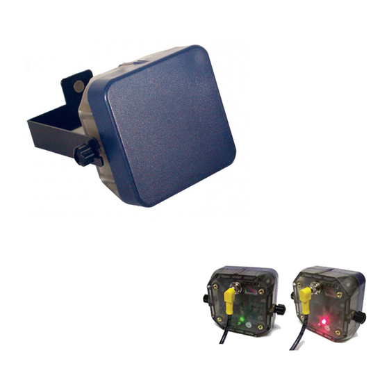
SYSTEM OPERATION RADAR REAR VIEW A. RUBBER WASHER: (2ea.) Rests on mounting screws between mounting bracket and radar unit. B. MOUNTING BRACKET SCREW: (2ea.) Connects bracket to radar unit. C. INDICATOR LED: Strongest target direction indicator. D. OPTIONAL MOUNTING INSERTS: (4ea.) Provides optional mounting for customer’s brackets. -
Page 9: Configuration Options
SYSTEM OPERATION CONFIGURATION OPTIONS The DRU III was designed to give the user a configurable radar unit that can be setup for their needs. A simple PC program let the user select: 1. Target Direction: The DRU III can output speeds for targets traveling in the direction of: a. - Page 10 6. Output Protocol: The DRU III can output one of several different protocols. Including outputs in HEX, ASCII, multiple targets, tenth units, and many others. 7. Output Baud Rate: The DRU III can be set to output RS232 data at rates of (19200, 9600, 4800, 2400, or 1200) baud.
- Page 11 If the DRU III is set to the Polled output, data is output when the DRU III receives characters [“*P”] or [“*P”0x0D].
-
Page 12: Installation
1. Mount the radar in its bracket. 2. Attach the end of the power/data cable to the 6-pin connector on the back of the DRU III. Ensure the plug and socket is aligned properly before tightening the screw ring. Ensure the connection is firm and tighten the connector’s screw ring. -
Page 13: Tuning Fork Test
SYSTEM OPERATION TUNING FORK TEST The DRU III unit can be configured to output speeds of targets that are approaching only, receding only, both approaching and receding, or all targets including non- directional targets. Tuning forks can only be reliably read in the all targets mode. - Page 14 SYSTEM OPERATION 3. Extremely cold or extremely hot tuning forks may give readings slightly above or below those specified, due to the effect of extreme temperature on the metal. If this is the case, warm or cool the forks to normal room temperature before use.
-
Page 15: General Information
Flash RS232 Serial Port EE Memory The Directional Radar Unit (DRU III) transmits a radio frequency of 24.125 Gigahertz, in accordance with Federal Communications Commission regulations. When the transmitted signal strikes a moving target, it returns at a different frequency because there is relative motion between the two objects (radar unit and target). - Page 16 GENERAL INFORMATION This returning signal is mixed with the transmitted signal in a balanced I/Q demodulator mixer. The difference in frequency (Doppler frequency) is proportional to the speed of the target; the difference in phase is related to the direction of target travel. These returned echo signals are a very low level.
-
Page 17: Power / Data Connector
5. Gray -- Ground 6. Pink – Open collector alarm LED INDICATOR The DRU III has a bicolor LED to indicate the status of the current strongest valid target. The statuses the LED can indicate are as follows: 1. Short burst of flashing red = DRU III is running, no valid target present. -
Page 18: Interference
Power transformers, radio transmitters, fans, etc generate electronic noise signals. If the power supply voltage to the DRU III unit drops below the level required for proper operation, power to the microwave transmitter will be turned off. This prevents false readings from occurring during periods of low voltage. -
Page 19: Recommended Care & Maintenance
NEVER wire directly into AC current!! 3. Do not pick up or carry the DRU III by the power / data cable. Do not yank or twist the cable, especially near the base. Broken wires inside the cables are a common cause of intermittent operation. -
Page 20: Ksi Radar Microwave Emission
Standards Institute, which recommends a maximum power density of 10.0 mW/cm for the frequency bands on which Kustom Signals traffic radar systems operate (ANSI C95.1- 1994, "American National Standards Safety Levels with Respect to Human Exposure to Radio Frequency Electromagnetic Fields, 300 KHz to 100 GHz"). - Page 21 While traffic radar devices do emit microwave radiation, the levels are so low that there are no possible harmful effects. You may use your Kustom Signals radar unit with complete confidence in its safety, as well as in its accuracy.
-
Page 22: Troubleshooting Guide
TROUBLESHOOTING GUIDE TROUBLESHOOTING If you are having operating difficulty, recheck the operating information in this manual, then check the following before notifying your Kustom Signals service representative of a problem. Problem Possible Solution No indications on Ensure power /data cable is firmly attached. -
Page 23: Technical Specifications
TECHNICAL SPECIFICATIONS MICROWAVE Frequency: 24.125 + .1 Ghz (K-Band) Output Power (EIRP): 20dBm Source: PHEMT or DRO Antenna Type: Planar Array Polarization: Linear Horizontal Beamwidth: Receiver Type: Dual Channel low noise GENERAL Supply Voltage 7.4 - 24.0 VDC Range: 12.6 VDC (nominal) Supply Current <... -
Page 24: References
IVQDRU-III Name of Grantee Kustom Signals Inc. The DRU III has been tested and found to comply with the limits pursuant to Part 15 of FCC Rules. These limits are designed to provide reasonable protection against harmful interference in a commercial environment. This equipment... -
Page 25: Warranty
Owner or Lessee. This Warranty applies only to the original registered • Owner or Lessee on file at Kustom Signals, Inc., and cannot be assigned or transferred to a third party. The Owner or Lessee shall use the Equipment in •... - Page 26 Owner or Lessee, as specified in the Operator’s Manual, and shall not apply to Equipment which has been defaced or damaged through normal usage. The liability of Kustom Signals, Inc., if any, with • respect to the equipment, shall be limited as provided in this Warranty.
Need help?
Do you have a question about the DRU III and is the answer not in the manual?
Questions and answers