Table of Contents
Advertisement
Advertisement
Table of Contents

Related Manuals for Kustom Signals EAGLE II


Summary of Contents for Kustom Signals EAGLE II
- Page 1 EAGLE ® Traffic Safety Radar OPERATOR’S MANUAL P/N 006-0765-40 REV. 0...
- Page 2 Kustom Signals, Inc., 9325 Pflumm Road, Lenexa, KS 66215-3347 Customer Service 1-800-835-0156 or (620) 431-2700...
-
Page 3: Table Of Contents
Table Of Contents INTRODUCTION ............1.1 SPECIFICATIONS ............2.1 2.0..............2.1 ENERAL 2.1............2.2 PERATIONAL INSPECTION & MOUNTING ........3.1 3.0........... 3.1 NITIAL NSPECTION 3.1..........3.1 ATERIALS UPPLIED 3.2..........3.2 QUIPMENT OUNTING UNIT DESCRIPTION ........... 4.1 4.0. - Page 4 Table Of Contents 7.5..... 7.9 ETTING NTERFERENCE ILTER 7.6..........7.10 AINTENANCE INTERFERENCE ............8.1 8.0..............8.1 VERVIEW 8.1..........8.1 ATURAL NFLUENCES 8.2........... 8.2 NFLUENCES 8.3............8.5 ROUNDSPEED RECOMMENDED CARE & MAINTENANCE..9.1 9.0. II..........9.1 AGLE CASE LAW ...............
-
Page 5: Introduction
® Eagle II units use Digital Signal Processing (DSP), which allows Kustom Signals designers the opportunity to add features such as same direction - fastest vehicle mode and ® the newest feature on all Eagle II series units, TruTrak. -
Page 6: Specifications
Section 2--Specifications 2. SPECIFICATIONS 2.0. General Type: Two piece, Moving/Stationary, True Doppler radar system. Frequency: 24.150 GHz + .1 GHz (K-band) 33.4 to 36 GHz + .1 GHz (Ka- Band). Tuning Forks: Forks stamped with “KSI Ka- Band” are for units with micro- wave frequency 35.5 GHz. -
Page 7: Operational
Section 2--Specifications Electronic Components: 100% solid state; integrated circuits, microprocessors and transistors tested for reliability. Operating Temperature: -22F to +140F -30C to +60C 90% relative humidity at 37°C, non-condensing. Dimensions: Counting Unit Height: 1.08" (2.74 cm) Width: 6.50" (16.51 cm) w/o mtg. knobs Depth: 3.75"... - Page 8 Section 2--Specifications Lock Time: Instantaneous. Patrol Window: Displays patrol speed. Target Window: Displays truncated target speed. Lock Window: Displays locked target speed. Display Type: High brightness LED Target, Patrol and Lock - .3" (7.62 mm). Light Intensity: Automatic dimming to ambient conditions.
- Page 9 Section 2--Specifications Indicators: Low Voltage: "Lo" displayed in TARGET window when supply voltage falls below input of 10.8 VDC. Locked speeds will remain. Radio Frequency "rFi" is displayed in TARGET Interference: window during radio frequency interference. Active speed displays will blank during this condition.
- Page 10 Section 2--Specifications Antenna: Height K-band 3.25" (8.26 cm) Ka-Band (ALL) 2.52" (6.4 cm) Width K-band 7.3" (18.54 cm) Ka-Band (ALL) 2.52" (6.4 cm) Depth K-band 3.6" (9.14 cm) Ka-Band 3.2" (8.13 cm) Ka-DCM 3.75" (9.5 cm) Weight K-band 1.88 lbs (0.85 kg) Ka-Band 0.7 lbs (0.32 kg) Ka-DCM...
-
Page 11: Inspection & Mounting
3. INSPECTION & MOUNTING 3.0. Initial Inspection Before installing your Eagle II, please take a moment to carefully inspect it for damage caused by shipping. Contact the shipping carrier at once if you notice any damage. Remove the unit from the shipping carton and check the packing list against your original purchase order. -
Page 12: Equipment Mounting
Available for each Eagle II radar system is an auxiliary power receptacle, which mounts under the dashboard and wires directly to the battery. - Page 13 1. The indicator unit contains the unit’s displays, switches, the circuit boards and processor. The Eagle II's display panel can be located overhead, on the dashboard or on the radio rack.
- Page 14 Section 3—Inspection & Mounting 3.2.2. Front Antenna Mounting Provided with the Eagle II is a windshield mount for the antenna. Contact your District Manager or Kustom Signals' Customer Service department for other optional antenna mounts. NOTE: Mounting of the antenna bracket to the dashboard or any metal bracket (such as the radio rack) may cause improper grounding of the antenna.
- Page 15 Section 3—Inspection & Mounting 5. Momentarily depress the AUDIO then the MODE switch. This places the Eagle II in the unsquelched (audio on) mode. If necessary, depress the AUDIO switch then the RANGE (up) switch to increase the audio level.
- Page 16 Section 3—Inspection & Mounting 7. After the optimum antenna position has been found, glue the bracket to the windshield using the adhesive provided. 8. Position of the antenna: Stationary: Maximum performance of the system will be achieved when the antenna is pointed directly toward the vehicles being monitored.
- Page 17 The plug connects into the “SPDOMTR” connector on the rear panel of the Eagle II. 2. The bare end of the speedometer pulse cable will be connected to the patrol vehicle’s electrical speedometer input cable using the splice connector provided.
- Page 18 Section 3—Inspection & Mounting If your vehicle year, make and/or model is not listed or you need hard copies, please contact Kustom’s Customer Service Department at (800) 835-0156. If you are outside of the US and Canada, please call (620) 431- 2700.
-
Page 19: Unit Description
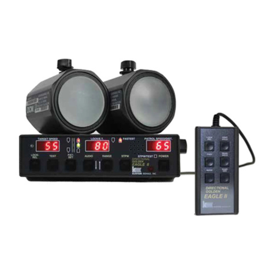
TEST LOCK- TEST MODE AUDIO RANGE HOLD POWER EAGLE II KUSTOM SIGNALS, INC. A. TARGET SPEED Displays the strongest speed of target vehicles in both stationary and moving modes. B. Road Graphic Graphic indicates which antenna is selected and the mode of operation. - Page 20 This switch used to display the level of audio currently selected. Secondary function is the decrement (down) control. I. RANGE (é) Switch used to place the Eagle II in the range set mode. Secondary function is the increment (up) control. Infrared wireless control J.
-
Page 21: Rear Panel
Section 4—Unit Description 4.1. Rear Panel The rear panel of the Eagle II has connectors for two antennas, remote control (wireless or wired), RS232 I/O port and Speedometer input cable. In addition, there is a captive power cord attached to the rear panel. -
Page 22: Remote Control
Remote Control LOCK HOLD FRNT REAR EAGLE II KUSTOM SIGNALS, INC. The remote control is available in either a wired or wireless version. The wired version plugs directly into the back panel's remote jack. The wireless remote uses an infrared sensor that plugs into the remote jack. - Page 23 4.2.0. Broken or Lost remote If the remote control is broken or lost, the operator can access most of the radar functions by placing the Eagle II in a default mode. 1. Power the Eagle II off. 2. Depress and HOLD the power switch. During the...
-
Page 24: General Theory Of Operation
(groundspeed) and is displayed in the PATROL display. The Eagle II series has an exclusive feature from Kustom Signals using the patrol vehicle’s speedometer pulses which steers the DSP processor to look for the Doppler signal in a specific speed range. -
Page 25: Microwave Rf Emissions
Section 5--General Theory of Operation patrol speed from the combined speed (120 - 55 = 65). The PATROL display would indicate 55 and the TARGET display would indicate 65. 5.1. Microwave RF Emissions Traffic radar operators may have some questions about the biological effects of exposure to the microwave energy produced by the radar devices. - Page 26 For a free copy of the latest information regarding the safe human exposure standards, please call or write Kustom to request the "RF Emissions Packet." You may contact us at our corporate headquarters: Kustom Signals, Inc. 9325 Pflumm Lenexa, KS 66215-3347 (913)492-1400 While traffic radar devices do emit microwave energy, the levels are so low that there are no probable harmful effects.
-
Page 27: Testing Procedures
Section 6--Testing Procedures 6. TESTING PROCEDURES 6.0. Overview The internal test and tuning fork tests explained below should be conducted at the beginning and end of each patrol shift to ensure the accuracy and functionality of the unit. The results of these tests may be recorded in a radar log, similar to the log found at the end of this manual. -
Page 28: Automatic Self-Test
The operator can depress the TEST switch at any time during normal radar operation to perform the lamp and internal tests as described in 6.4. If the Eagle II is in the stopwatch mode and a timing cycle is in process, the test switch is inoperative until the timing cycle has ended. -
Page 29: Accuracy Testing
Momentarily depress the TEST switch. Holding the TEST switch depressed will light all displays. Upon releasing this switch, the Eagle II will complete the internal test. If these tests pass, the TARGET window will display "PAS". If the TEST button is held depressed for greater than 10 seconds, the internal test will proceed as a default condition. -
Page 30: Tuning Fork Testing
Tuning fork test tolerance: + 1 MPH (1 km/h). ** Due to the ability of the Eagle II to reject interfering signals, if the antenna label reads “DCM” the operator must place the unit in the TEST mode to read tuning forks. - Page 31 Section 6--Testing Procedures 6.5.0. Stationary & Opposite Direction Moving Modes 1. Press the MODE switch, placing the Eagle II in the stationary mode (both direction antenna/mode indicators should be on). Use the remote control to change to the desired antenna. If the unit is displaying "Hld" in the TARGET window, depress the HOLD switch on the front panel to place the unit in a transmitting mode.
- Page 32 Depress the LOCK/REL switch a second time and the locked speed should be erased. 8. Depress the MODE switch and place the Eagle II in the moving mode, opposite direction, front antenna. Only the patrol LED and the front, opposite direction LED indicator will be lit.
- Page 33 NOTE: Do not move the tuning forks after they have been placed in front of the antenna. 3. Ensure that the Eagle II is not in the HOLD mode and that the RANGE control is set to 6 (maximum range).
-
Page 34: Moving Mode Test
6.7. Speedometer Input Synchronization The initial use of the Eagle II with speedometer pulse input requires the radar unit to be synchronized with the speedometer. 1. After installation and initial testing with tuning forks, the Eagle II should be driven at a constant speed between 30 and 70 MPH (48 and 112 km/h). - Page 35 35. A BMW motorcycle will read around 10. This indicates the Eagle II is reading and comparing the speedometer pulses and the Doppler patrol signal. NOTE: Only the actual radar Doppler signal is used for patrol speed.
-
Page 36: System Operation
Section 7--System Operation 7. SYSTEM OPERATION 7.0. Operating Modes The Eagle II is designed to be the most complete radar system ever developed for law enforcement use. It has 4 different operating modes: 1. Stationary Front Antenna 2. Stationary Rear Antenna 3. -
Page 37: Setup
Section 7--System Operation 7.1. Setup 1. Select a location that provides a good view of the traffic to be monitored. 2. Check the immediate area for potential interference sources, such as large reflecting signs in the direct path of the radar's microwave beam, power substations and other sources of electrical interference. - Page 38 "rnG" and the PATROL window will display the current level (1 - 6). Range level 6 is maximum range, range level 1 reduces the Eagle II's range to its minimum distance, typically 250 feet. Depressing the DOWN (AUDIO) or UP (RANGE) switches will decrease or increase the range level.
-
Page 39: Stationary Operation
Switch to the desired antenna. Set range to the desired level. (Level 1, target must be very close before the Eagle II will display the target's speed, Level 6, maximum range.) Set fan interference filter to the desired state (see previous section). - Page 40 A short alert tone will be heard and the target speed will be displayed in the LOCK window. 5. The Eagle II will continue to track the violator's speed in the TARGET window as long as the vehicle is in the antenna beam.
-
Page 41: Moving Operation
4.2.0 for default operation of the Eagle II without a remote control. 7.3. Moving Operation 1. Place the Eagle II in the moving mode of operation by depressing the MODE switch and observing the mode/antenna indicators. The patrol and an opposite direction indicator should be lit. - Page 42 6. To lock the violator's speed, depress the LOCK switch. A short alert tone will be heard and the LOCK window will display the speed of the target vehicle. 7. The Eagle II will continue to track the target and patrol speeds.
- Page 43 11. If the operator changes the mode of operation, the locked speeds will be automatically unlocked and cannot be recalled. Depressing the TEST switch will allow the Eagle II to complete a lamp and internal test then return the locked speed.
-
Page 44: Speedometer Pulse Operation
The radar may be operated with or without the speedometer pulse input. If it is not connected to the speedometer pulse input, it will operate as a standard radar. If the Eagle II is connected to the speedometer pulse input, it will operate as a standard radar until it detects speedometer pulses. -
Page 45: Maintenance Mode
Section 7--System Operation 7.6. Maintenance Mode The Eagle II has a maintenance/configuration mode, which can be used by technicians for diagnosis and troubleshooting. This mode can be accessed by holding the POWER switch depressed for 5 seconds or longer. It can be immediately exited by pressing the HOLD switch or by turning the unit off and back on again. -
Page 46: Interference
2. Terrain can affect the range of the Eagle II. Improper aiming of the antenna can cause the radar to appear to have short range. If the target vehicle were on a slight incline, the antenna could be shooting short of the intended target vehicle. -
Page 47: Man-Made Influences
This difference speed may be placed in the PATROL window and used instead of the proper patrol speed. See Section 8.3. NOTE: If the Eagle II is displaying a low patrol speed due to shadowing, entering and exiting HOLD quickly should resolve the problem 3. - Page 48 5. If the power supply voltage drops below the minimum operating voltage, the Eagle II will not display any new speed-readings until the low voltage condition is no longer exists. "Lo" will be displayed in the TARGET window.
- Page 49 7. Heater and A/C fan motors can cause conventional analog radar units to display the fan's speed, rather than a weaker target vehicle's speed. The Eagle II's DSP processing attempts to distinguish fan speeds from actual vehicles and will ignore fan interference signals.
-
Page 50: Groundspeed
HOLD mode. In most instances this tactic will also eliminate a combined speed in the PATROL window. The Eagle II's DSP system will always look for and display groundspeed before displaying any targets. The groundspeed radar signature is unlike any target or interference signal. - Page 51 Section 8--Interference Operating moving radar in the rain, fog, or snow requires the operator to pay close attention to the patrol speed. Since rain, fog and snow may affect the ability of the radar system to find groundspeed, the operator must verify that the radar's patrol speed and the patrol vehicle's speedometer agree within allowable limits.
-
Page 52: Recommended Care & Maintenance
4. There are no user serviceable parts in the Eagle II. Inside the unit is an over current protection device that will shut the radar down if this condition exists. After the over current condition is removed, the protection device will again allow normal operation. - Page 53 Receiver diode degradation has no effect on the unit's accuracy, but will result in unsatisfactory target range. 7. Kustom Signals recommends periodic maintenance of the Eagle II radar system. Check with your local service center and judicial district for requirements.
-
Page 54: Case Law
Since the Eagle II is a Doppler based traffic radar system, some older case law is presented because of its significance to the acceptance of the Doppler principles as well as the basic requirements of the tuning fork test and operator training. - Page 55 Section 10--Case Law The court held and took judicial notice of the accuracy of Doppler radar in both the stationary and moving modes of operation. Reference E -- Samuel Knight vs. State of New York Superior Court. 72 N.Y. 2d 481, 530 N.E. 2d 1273 (1988). The court ruled that a trained operator, who properly tested the radar, observed the traffic and checked the patrol speed against the patrol vehicle's speedometer, can accurately...
-
Page 56: Fcc Licensing
Section 11--FCC Licensing 11. FCC LICENSING 11.0. FCC – Transmitter Rules Amended The Federal Communications Commission (FCC) has amended its rules to eliminate the required annual measurement of transmitter power, frequency and modulation and to specify transmitter power in terms of output power for licensees in the Public Safety, Industrial and Land Transportation Radio Services. -
Page 57: Fcc - Licensing
Section 11--FCC Licensing 11.1. FCC – Licensing The Commission has eliminated the requirement for local governmental entities licensed in the Public Safety Radio services to obtain a separate authorization for radar speed detection devices. This change reduces paperwork for the Commission's licensing staff and for police and other local government units, which no longer have to apply for new radar authorizations or modify or renew existing licenses and may... - Page 58 Section 12--Troubleshooting 12. TROUBLESHOOTING If an operating difficulty is encountered, check the following list of possible problems and solutions before returning the unit to the factory or local Service Center. Problem Possible Solution No Power Indication Check for proper voltage at cigarette plug.
-
Page 59: Troubleshooting
Section 12--Troubleshooting No target speeds Verify the unit is NOT in the during tuning fork HOLD mode. test (cont) Unsquelch audio. Listen for Doppler tone. Verify (moving mode) that patrol speed is showing the correct speed—30 or 35 MPH (45 km/h). Lightly strike the tuning fork and retest. - Page 60 Section 12--Troubleshooting No target readings in Verify that the unit is NOT in the stationary mode HOLD mode. Verify the range control is set properly. Verify the desired antenna is selected. Verify the antenna is aimed properly and the target is within range of the radar.
- Page 61 Section 12--Troubleshooting No patrol speed (unit Weather conditions (heavy rain, not in lock) (cont) snow or fog) may affect the Eagle II’s ability to pick up groundspeed. Verify the patrol speed is above the minimum patrol speed setting and below 100 MPH (160 km/h). To check the setting, press PAT/SEL.
- Page 62 Section 12--Troubleshooting Speedometer input will Verify unit is not in HOLD. not synchronize Verify the speedometer input cable is connected properly. Verify the remote control is connected properly. Patrol speed must be between 30- 70 MPH (48-112 km/h). (Refer to Sec.
- Page 63 Verify there are no obstructions between the antenna and the target. Weather conditions (heavy rain, snow or fog) may affect the Eagle II's range. Check for electrical influences. Place radar in stationary mode, unsquelch audio and listen for interferences in audio.
- Page 64 Section 12--Troubleshooting Short range (cont) Strong fan interference will reduce the operating range of the Eagle II. Refer to Sections 7.1 and 7.5 for information on the fan interference filter. NOTE: Use of the shielded auxiliary power cable may eliminate the vehicle's electrical noise problems.
- Page 65 Section 12--Troubleshooting Intermittent Readings Weather conditions (heavy rain, (cont) snow or fog) may affect the Eagle II's ability to pick up proper groundspeed or the target vehicle. Verify vehicle electrical influences. (See "Short Range" listed above.) Fan interference Place unit in stationary mode.
-
Page 66: Options
Section 13--Options 13. OPTIONS 13.0. Options setup The Eagle II radar unit allows the operator to change certain operating parameters of the unit. The following is a list of the available parameters. Each has a number after the option. An example will be given to instruct the operator how to change the unit. -
Page 67: Options Descriptions
13.1.1. Minimum Audio Level The Eagle II defaults to allow the audio level to be to 0 (audio off). If it is required that the audio cannot be turned off, add 4 to the Options total. -
Page 68: Options Examples
Section 13--Options 13.1.3. Interface Output Protocol The Eagle II defaults to allow the radar unit to interface the ® KSI Eyewitness video or giant display equipment. Contact Kustom's Customer Service Department at (800)-835-0156 or (620) 431-2700, before changing the output protocol option. - Page 69 Section 13--Options EXAMPLE: The operator wishes to permanently change the operation of the unit to the following: Automatic Unlock = 1, no Patrol Blank = 8, Gateway (unencrypted) output = 32 and MPH = 0. These numbers are added for a total of 41.
-
Page 70: Warranty
Owner or Lessee. • This Warranty applies only to the original registered Owner or Lessee on file at Kustom Signals, Inc., and cannot be assigned or transferred to a third party. The Owner or Lessee shall use the Equipment in •... - Page 71 Owner or Lessee, as specified in the Operator’s Manual, and shall not apply to Equipment which has been defaced or damaged through normal usage. The liability of Kustom Signals, Inc., if any, with • respect to the equipment, shall be limited as provided in this Warranty.
- Page 72 Section 14--Warranty EQUIPMENT SUPPLIED WITH CONSUMABLE ITEMS Items such as tires, non-rechargeable batteries, light bulbs, transmitter carrying pouch, and microphone cables w/microphone and windscreen are considered consumable items and as such are not covered by this warranty. SMART RADAR SMART system radar units are warranted for two years, subject to the warranty terms listed above.
- Page 73 INDEX Accuracy..................2.1 Audio Control..............3.5, 4.2, 7.2 Case Law ................. 10.1 Connectors................. 4.3 Cosine Factor................7.2 Display Function................. 4.1 Size ..................2.3 Display Dimming..............4.2 Equipment Mounting..............3.2 Equipment Supplied..............3.1 Fan Filter ................3.5, 7.3 Fan Interference ......3.5, 7.3, 7.9, 8.2, 8.4, 12.7, 12.8 FCC Licensing ................
- Page 74 INDEX Indicators ................2.4, 4.1 Inspection .................. 3.1 Installation Airbag Information ............... 3.3 Auxiliary Power Receptacle..........3.2 Front Antenna ............... 3.4 Indicator................. 3.3 Rear Antenna................. 3.6 Speedometer Pulse Cable ............. 3.7 Interference Man-Made ................8.2 Natural ................... 8.1 Law ................See Case Law LOCK/REL Auto Release ..........
- Page 75 INDEX Options..................13.1 Available ................13.1 Descriptions................. 13.2 Examples ................13.3 Patrol Speed Blanking ............4.5, 7.8 Power Receptacle Auxiliary................3.2 Location................. 4.3 Range Control ..............4.2, 7.3 Rear Panel.................. 4.3 Remote Control ................. 4.4 Broken or Lost ..............4.5 Setup ..................7.2 Specifications General ..................
- Page 76 INDEX Switches AUDIO .................. 4.2 Display Unit ................4.1 FRNT/REAR................. 4.4 HOLD ................4.2, 4.4 LOCK/REL ..............4.1, 4.4 MODE ................... 4.1 PAT/SEL ................4.5 POWER ................. 4.2 RANGE ................. 4.2 Remote Control..............4.4 TEST..................4.1 Test Indicator................4.2 Test Mode.................. 6.4 Testing ..................
- Page 77 INDEX Unsquelch Audio............3.5, 4.1, 7.2 Video Interface Protocol..........13.1, 13.3 Warranty.................. 14.1...
- Page 78 For additional mounting suggestions, please contact the Kustom Signals Customer Service Department. Kustom Signals cannot accept any liability for equipment, which has been mounted in conflict with the vehicle manufacturer's recommendation for proper airbag deployment.
- Page 79 _____________ UNIT SERIAL NUMBER ON DUTY TEST OFF DUTY TEST FORK/ DRIVE/ FORK/ DRIVE/ DATE TEST SIGN TEST SIGN COMMENTS READ READ RADAR RADAR...
Need help?
Do you have a question about the EAGLE II and is the answer not in the manual?
Questions and answers