Table of Contents
Advertisement
Quick Links
Advertisement
Table of Contents

Related Manuals for UNI-T UTE310


Summary of Contents for UNI-T UTE310
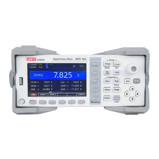
- Page 1 User’s Manual UTE310 Digital Power Meter...
-
Page 2: Table Of Contents
User’s Manual UTE310 Digital Power Meter Table of Contents Perface ............................6 Copyright ............................. 6 Warranty Service .......................... 6 Limited Warranty and Liability ...................... 7 Chapter 1 Safety Instruction ........................8 1.1 Safety Information ........................9 1.2 Environmental Condition ......................11 Chapter 2 Inspection and Installment ..................... - Page 3 User’s Manual UTE310 Digital Power Meter Chapter 5 Measurement Settings ......................36 5.1 Range Settings ........................36 5.1.1 Voltage Range Settings ....................36 5.1.2 Current Range Settings ....................36 5.1.3 Range Switching ......................37 5.2 Measurement Mode ....................... 38 5.3 Meter Common Measurement and Settings ................39 5.3.1 VIEW-1 ..........................
- Page 4 User’s Manual UTE310 Digital Power Meter 6.1.8 Reset Init (Initialization) ....................64 6.2 Average Filter (AVG) ....................... 65 6.2.1 Average State (Turn on/off) ..................66 6.2.2 Average Type ......................66 6.2.3 Count (Average factor) ....................67 6.3 External Current Sensor (EXT) ....................67 6.3.1...
- Page 5 8.3 USB Interface ........................89 8.3.1 PC Connect to UTE310 via USB ..................90 8.4 GPIB Interface (Optional) ....................... 90 8.4.4 PC Connect to UTE310 via GPIB Interface ................91 Chapter 9 Storage and Calibration ......................93 9.1 Notices for Storage ....................... 93 9.2 Trouble-shooting ........................
-
Page 6: Perface
UNI-T or an authorized UNl-T distributor. Power cords, accessories and fuses, etc. are not included in this warranty. If the product is proved to be defective within the warranty period, UNI-T reserves the rights to either repair the defective product without charging of parts and labor, or exchange the defected product to a working equivalent product (determined by UNI-T). -
Page 7: Limited Warranty And Liability
If the products is shipped domestically to the purchase receipt of the original purchaser. If the product is shipped to the location of the UNI-T service center, UNI-T shall pay the return shipping fee. If the product is sent to any other location, the customer shall be responsible for all shipping, duties, taxes, and any other expenses. -
Page 8: Chapter 1 Safety Instruction
UNI-T assumes no responsibility for the user's failure to comply. Do not use damaged equipment. Before using the device, check its outer shell. Check whether has cracks or missing plastic. -
Page 9: Safety Information
User’s Manual UTE310 Digital Power Meter and serious consequences. The circuits shall not be exposed. Do not touch exposed connectors and components after power is turned on. 10. Use the appropriate fuse, only use the fuse type and rating indicator specified for this product. - Page 10 Upon expiration of this period, it should enter the recycling system. Warning The UTE310 Digital Power Meter only supports measurement of power supplies under CAT II (600V) type overvoltage conditions, so please use the instrument strictly in accordance with this measurement environment.
-
Page 11: Environmental Condition
Before handling and cleaning the instrument, please disconnect the instrument from the power supply to avoid danger, and use a clean dry cloth to wipe the instrument. 1.2 Environmental Condition UTE310 digital power meter can only use indoors and non-condensing area, the general environmental requirements are shown as below table. Environmental Condition Operating Environment 5℃~40℃,20%~80%RH(non-condensing)... -
Page 12: Chapter 2 Inspection And Installment
Chapter 2 Inspection and Installment 2.1 Check Packing List Check with packing list to confirm that accessories has no loss or abnormal. If there have any problem, please contact with UNI-T distributor or manufacture. Product Model Product Name... - Page 13 User’s Manual UTE310 Digital Power Meter Transformati Accura Pore Brand Model Sensor Current Bandwidth Interface Appearance on ratio Size AC and DC CYBER ZCP20 current 20Arms 0.1V/A 0.30% 1MHz 20mm 12 pin clamp AC and DC CYBER ZCP20 current 200Arms 10mV/A 0.30%...
- Page 14 User’s Manual UTE310 Digital Power Meter AC and AC/DC: 2000- 1:2000 0.0018% 140kHz 70mm 2000A sensor AIT Series High Precision Current Sensor Senso Transformatio Accurac Bandwidt Pore Interfac Brand Model Current Appearance n ratio Size AIT3000- DC:3000A, Current Hangzh 1:3000 0.0050%...
- Page 15 User’s Manual UTE310 Digital Power Meter AC and LF205- 100Arms 1:1000 ± 0.5% 100kHz 15.5mm 3 PIN S/SP3 (DC/AC) sensor AC and LF205- 200Arms 1:2000 ± 0.5% 100kHz 15.5mm 3 PIN (DC/AC) sensor AC and 500Arms LF505- (DC/AC) 1:5000 ± 0.6% 100kHz 32.2mm...
-
Page 16: Handle
User’s Manual UTE310 Digital Power Meter 2.2 Handle The instrument’s handle can adjust to four positions by appropriate strengths. Hold the handle and pull to two sides to remove it. Adjusting the handle to the position as shown in the following figure. -
Page 17: Features
User’s Manual UTE310 Digital Power Meter UTE310 is a high precision and high performance digital power meter. The current measurement range is 25uA~20A, which meets the requirement of production, test and R&D. UTE310 digital power meter is suitable for the power measurement from production line to R&D field. - Page 18 25mA~20A The data update interval can up to 0.1s UTE310 digital power meter can freely set the data update interval: 0.1s, 0.25s, 0.5s, 1s, 2s, 5s, 10s, 20s, Auto, to meet the measurement needs of different frequency signals. Instruments.uni-trend.com...
-
Page 19: Application System
User’s Manual UTE310 Digital Power Meter 3.3 Application System The application system chart of the UTE310 digital power meter is shown in the following figure. 3.4 Technical Index f: Frequency Rate: Data update interval CF: Crest factor Model UTE310 Bandwidth DC, 0.1Hz~300kHz... - Page 20 User’s Manual UTE310 Digital Power Meter CF=3 CF=6 or 6A 2.5mA 10mA 20mA 10mA 50mA 25mA 100mA 50mA Current Range 200mA 100mA 500mA 250mA 0.5A 2.5A Current Resolution 0.0001mA/0.001mA/0.01mA/0.1mA/1mA CF=3 CF=6 or 6A 2.5V 1.25V Ext1 Sensor CH Range 2.5V...
-
Page 21: Front Panel
Average active power integral, current integral Mathematical Operation √ DA Output and Control √ Communication Interface RS-232/GPIB, LAN, USB 3.5 Front Panel This section is to introduce the panel and key function of the UTE310 digital power meter. Instruments.uni-trend.com 21 / 99... -
Page 22: Key Function On Front Panel
User’s Manual UTE310 Digital Power Meter 3.5.1 Key Function on Front Panel Function The power switch ON/OFF: Press one time to turn on the instrument, press it again to shut down the instrument. Common function key This indicates the different functions according to the corresponding parameters of the display. -
Page 23: Key Combination
User’s Manual UTE310 Digital Power Meter Waveform display Display the waveform of voltage and current. Integral key The average active power and current can be integrated. Lock key Press this key to disable other keys, long press 1 second to unlock keys. -
Page 24: Description Of Display Screen
User’s Manual UTE310 Digital Power Meter 3.5.3 Description of Display Screen Display Contents Function Description Indicates that the voltage is a fixed range of 15V /30V /150V /300V /600V U-RANGE 15V /30V /150V /300V /600V respectively (each range is one-half of the current range when CF=6 or 6A). - Page 25 User’s Manual UTE310 Digital Power Meter Indicates that the frequency filter is enabled. RMS/DC/MN Indicates that the measurement mode is RMS/DC/MN. SYNC.OFF Indicates that the synchronous source is not set. SYNC.U Indicates that the voltage is set as a synchronous source.
-
Page 26: Rear Panel
The rear panel of the UTE310 digital power meter is integrated various interfaces, such as the voltage and current measurement input terminals, the power supply socket of instrument, D/A output and control interface, the communication interface of RS-232/GPIB, USB and LAN, and safety grounded, as shown in the following figure. -
Page 27: Chapter 4 Operation Preparation And Wire Connection
User’s Manual UTE310 Digital Power Meter Rear Panel of UTE310 Picture Function Description Voltage input terminal The maximum allowable input voltage is 600V. Current input terminal The maximum allowable input current is 20A. External current sensor input terminal The maximum allowable input voltage is 10V when EXT1 is selected. The maximum allowable input voltage is 2V when EXT2 is selected. -
Page 28: Wire Connection
The UTE310 has two input methods for voltage measurement, four input methods for current measurement, and a total of eight input methods for power measurement. These are shown in the table below. -
Page 29: Direct Input Voltage And Wire Connection Of Current (①)
User’s Manual UTE310 Digital Power Meter Turn off the power supply of the load and the instrument when the load end is wiring. When measuring large currents/voltages or the current containing high frequency components, special attention should be paid to the possibility of mutual interference and noise problems when wiring. -
Page 30: Direct Input Voltage And Wire Connection Of Ct Transformer (②)
User’s Manual UTE310 Digital Power Meter Wire connection schematic diagram when measuring the signal with small current Explanation In order to minimize the effect of stray capacitance on the measurement results, the measurement can be connected to the current input of the power meter as close as possible to the power supply ground, and use the thicker and shorter wires for the wire connection. -
Page 31: Direct Input Voltage And Wire Connection Of Ext (③)
User’s Manual UTE310 Digital Power Meter current transformer (CT) open-circuited, as it can cause high voltage transients and electric shock. 4.2.3 Wire Connection of Direct Input Voltage and EXT Input Current (③) The current sensor of output voltage type must be selected when using EXT CH. The measurement circuit connecting method is shown in the following figure. -
Page 32: Vt Transformer And Wire Connection Of Direct Input Current (⑤)
User’s Manual UTE310 Digital Power Meter input terminal of EXT, and then connecting the input terminal of EXT to the sensor input of the instrument, and finally connecting CT to the circuit to be tested. Cautions The measurement accuracy of this method is very rely on the accuracy of external sensor. If use this way to measure the equivalent accuracy of current sensor, the measured data error will be enlarged, so do not use this measurement method unless it is necessary. - Page 33 User’s Manual UTE310 Digital Power Meter Warning The secondary side of CT will product high voltage when using the CT. When the current is flowing on the primary side, please avoid the secondary side of CT is open-circuit, otherwise, it will be very dangerous. Connecting the common port (-) on the secondary side of VT/CT to ground to ensure security, as shown in the following figure.
-
Page 34: Vt Transformer And Wire Connection Of Ext (⑦)
User’s Manual UTE310 Digital Power Meter 4.2.7 Wire Connection of VT Transformer Input Voltage and EXT Transformer Input Current (⑦) Warning Do not use bare sensor, it may cause electric shock. Please make sure that the sensor is intact and the energized parts of the sensor are insulated from the box, and the sensor need have sufficient voltage-resistant for the voltage used in the measuring circuit. -
Page 35: Connecting Power Supply
User’s Manual UTE310 Digital Power Meter Warning When using the CT, be sure to fully understand the specification of voltage and clamp current sensor, the operating method and the dangerous factors (such as electric shock). When using the EXT, do not touch the CT or connecting test cables. When the power of measuring circuit on EXT is enabled, the CT will produce the voltage, so it is dangerous. -
Page 36: Chapter 5 Measurement Settings
User’s Manual UTE310 Digital Power Meter Chapter 5 Measurement Settings 5.1 Range Settings 5.1.1 Voltage Range Settings ·Steps 1. In any interface, press the [Voltage] key to pop out the selection window of voltage range; 2. Press the [▲] or [▼] key to select the voltage range;... -
Page 37: Range Switching
User’s Manual UTE310 Digital Power Meter The display interface will synchronize the currently selected current range. Auto represents the automatic range. When CF=6 or 6A, all ranges will be reduced to half of the original, i.e. Ext1: Auto, 1.25V, 2.5V, 5V. -
Page 38: Measurement Mode
125%, and the current peak Ipk is less than or equal to the previous scale of 600% (CF=6 or 6A). 5.2 Measurement Mode UTE310 series has three measurement modes. The user can set the mode according to the signal type or the value to be displayed. Setting Steps 1. -
Page 39: Meter Common Measurement And Settings
User’s Manual UTE310 Digital Power Meter follows. �� ��(��) �� f(t): Input signal T: Period of input signal DC mode: select this mode when input DC voltage and current, calculating the simple average for the input signal. The calculation formula is as follows. -
Page 40: View-1
User’s Manual UTE310 Digital Power Meter 5.3.1 VIEW-1 Press the [Meter] key to select Meter common measurement function (Meter indicator will be illuminated), the default selection is VIEW-1. VIEW-1 has four test interfaces, the first interface displays the voltage (such as RMS voltage, voltage calibration average value, voltage AC component, voltage DC component, voltage positive peak value, voltage negative peak value);... -
Page 41: View-2
User’s Manual UTE310 Digital Power Meter 5.3.2 VIEW-2 VIEW-2 can display 14 parameters at the same time. The user can choose this display style when they need to observe several parameters at the same time. Press the [Meter] key to enter the Meter measurement menu, and then press the function key below VIEW-2 to switch to the VIEW-2 display style, as shown in the following figure. - Page 42 User’s Manual UTE310 Digital Power Meter F2, F3 corresponding to the function indication. For the sake of simplicity, respectively, use F1, F2, and F3 to describe its function in this subsection. Explanation F4: Press the “F4” key to display SEL-A, SEL-B, SEL-C, SEL-D in sequence, which means the display area A, B, C, D is selected, and then press "F5"...
-
Page 43: Harmonic Measurement
User’s Manual UTE310 Digital Power Meter = | Z | Arbitrary �� = | X | AA/B: Display the result of dividing the square of area A by the area B Calculating the resistance (R) Display Area A Display Area B... -
Page 44: Bar Graph
User’s Manual UTE310 Digital Power Meter Bar Graph Mode List Mode Explanation FUNC U/A/P can only be displayed at bar graph. In the list mode, if there is no input signal or the harmonic measurement is abnormal (no analyzed times), the value of each harmonic is displayed as ------, e.g. in IEC mode, the 41st to 50th harmonics are displayed as ------, and the rest of the times can be displayed as actual. -
Page 45: Harmonic Set
User’s Manual UTE310 Digital Power Meter Display the voltage, current and RMS of Display the distortion factor of each Display the phase angle of voltage and power of each harmonics harmonics current of each harmonics Pressing the [ ] or [ ] key to switch to the display mode (display the harmonic content or harmonic ratio), pressing the [▲] or [▼] key to turn the page to display the harmonic component of different orders. - Page 46 User’s Manual UTE310 Digital Power Meter CSA: Calculating the ratio of the RMS of the 2~50 harmonic components to the RMS of the 1~50 harmonic components, the formula is as follows. THD = k=1 : Fundamental wave component : Fundamental wave component and harmonic content...
-
Page 47: Wave Display
User’s Manual UTE310 Digital Power Meter 75Hz≤f<150Hz f×512 150Hz≤f<300Hz f×256 300Hz≤f<600Hz f×128 600Hz≤f≤1200Hz f×64 IEC measurement mode: (measured by the standard IEC61000-4-7:2002), use the time window of 200ms to calculating FFT, the maximum number of THD calculations is 40. The measurement method is shown the following table. -
Page 48: Time Axis
5ms/div, 10ms/div, 25ms/div, 50ms/div, 100ms/div, 200ms/div, 500ms/div, 1s/div, and 2s/div. 5.5.2 Vertical Axis The vertical axis scale of the UTE310 waveform display is automatically selected by the instrument and cannot be changed by the user through the key setting. The vertical axis scale for voltage and current is (rated range/3)/div. -
Page 49: Normal Integration
User’s Manual UTE310 Digital Power Meter Current integration in continuous mode Integration mode can select to Normal or Continuous. The default mode is Normal. Integration state includes three states, the start, stop and reset state. Start represents that the integration is processing. -
Page 50: Continuous Integration
User’s Manual UTE310 Digital Power Meter continue to integration, the integration will automatically stop and keep the integrated value and integration time when the integration time reaches the set time of the timer. Pressing the combination key [Shift + Reset] to reset the integrated value and integration time, and then press the [Start] key again to start the next integration. -
Page 51: Comparsion Of Integration Mode
User’s Manual UTE310 Digital Power Meter Set Time: time of integration timer Test Time: integration time Cautions In the continuous integration mode, the time if timer cannot be 0, pressing the [Start] key when the timer sets to 00000:00:00, the instrument will pop out “Error, the integration time of continuous mode must be more than…”... - Page 52 User’s Manual UTE310 Digital Power Meter stopped when the integration time reaches to the maximum value. Press the [Stop] key The integration will be stopped when integration reaches to the set time of timer. Standard The integration will be Press the [Start]...
-
Page 53: Integration Mehod
User’s Manual UTE310 Digital Power Meter the integration Explanation time reaches to the The minimum value is set time, and the negative value. next integration Press the [Stop] key will be restarted. 5.6.4 Integration Method The integration is calculated differently for different measurement modes. If the measurement mode is DC, the instantaneous values of power and current are integrated;... - Page 54 User’s Manual UTE310 Digital Power Meter Select the integration mode “Continuous” or “Normal” by pressing the [ ] or [ ] key. Save the selected mode and exit the integration mode settings by pressing the [Enter] key. Integration Timer ...
-
Page 55: Integration Operation
User’s Manual UTE310 Digital Power Meter current integration q. Press the “F2” key to switch to the parameter with big font. When WP is selected by the “F1” key, the integration interface displays WP, WP+ and WP-. When q is selected by the “F1” key, the integration interface displays q, q+ and q-. -
Page 56: Limitations During Integration
User’s Manual UTE310 Digital Power Meter 5.6.7 Limitations during Integration During integration, theses settings will be limited. “√” indicates the setting can be operated. “/” indicates the setting cannot be operated. Function Integrating Integration Stopped Integration Reset Meter √ √... -
Page 57: Chapter 6 Setup Menu
User’s Manual UTE310 Digital Power Meter Frequency filter √ √ Crest factor √ √ Data update √ √ Automatic time-out √ √ Automatic data synchronization √ √ source Initialization √ √ √ Average filter √ √ External sensor CH √... -
Page 58: Setup
User’s Manual UTE310 Digital Power Meter 6.1 SETUP Pressing the [SETUP] key in any interface to enter the Setup menu, press the arrow key [▲], [ ▼], [ ], [ ] to select or switch to the parameter setting, as shown in the following figure. - Page 59 User’s Manual UTE310 Digital Power Meter The UTE310 digital power meter finds the measurement data by averaging the sampled data over the measurement interval. The period of the input signal is detected from the voltage signal and current signal, and the user can set the voltage signal (U) or current signal (I) as the synchronization source.
-
Page 60: Line Filter
6.1.2 Line Filter The line filter can remove the high frequency component in measurement circuit. The UTE310's line filters are designed to be used in the measurement circuits of voltage, current and power, and when the line filters Instruments.uni-trend.com... -
Page 61: Frequency Filter
6.1.3 Frequency Filter The UTE310’s frequency filter is designed for frequency detection circuit, the cut-off frequency is 500Hz. It is used to accurately detect zero crossing points of synchronized source signals when detecting measurement intervals. The frequency filter has an effect both on the frequency measurement and on the measurement interval for detecting voltage, current and power. -
Page 62: Crest Factor
User’s Manual UTE310 Digital Power Meter 6.1.4 Crest Factor The crest factor is defined as the ratio of the peak value of the waveform to the RMS value. It is also referred to as the peak-to-rms ratio. Peak value Crest factor = RMS value The crest can be set to 3, 6, or 6A. -
Page 63: Auto Timer (Timeout)
User’s Manual UTE310 Digital Power Meter DC,1Hz~300kHz DC,0.5Hz~300kHz DC,0.2Hz~300kHz DC,0.1Hz~300kHz DC,0.1Hz~300kHz Auto A slower data update interval can capture the low frequency signal. A faster data update interval can capture the fast-changing signal, such as a rapidly changing load in a power system. If the period of the input signal varies greatly, set the data update period to Auto. -
Page 64: Auto Rate Sync (Automatic Data Synchronization)
User’s Manual UTE310 Digital Power Meter Timeout Setup Using the [▲] or [▼] key in the SETUP menu to select “Auto Timer” (the option is fill with red shading which means it is selected). 2. Pressing the [ ] or [ ] key to select 1s, 2s, 5s, 10s, 20s. -
Page 65: Average Filter (Avg)
User’s Manual UTE310 Digital Power Meter SCALE JUMP Initialization Setup Using the [▲] or [▼] key in the SETUP menu to select “Reset Init” (the option is fill with red shading which means it is selected). 2. Pressing the [Enter] key to perform the initialization. -
Page 66: Average State (Turn On/Off)
User’s Manual UTE310 Digital Power Meter 6.2.1 Average State (Turn on/off) Setting Steps Using the [▲] or [▼] key in the AVG menu to select “Average state” (the option is fill with red shading which means it is selected). 2. Pressing the [ ] or [ ] key to select OFF or ON, the icon AVG-8 (the average factor selects 8) will be displayed when it selects ON. -
Page 67: Count (Average Factor)
User’s Manual UTE310 Digital Power Meter Using the [▲] or [▼] key to select other setting option or pressing the [ESC] key to go back to the measurement interface. 6.2.3 Count (Average factor) Setting Steps Using the [▲] or [▼] key in the AVG menu to select “Count” (the option is fill with red shading which means it is selected). -
Page 68: Ext1 Ratio (Mv/A)
User’s Manual UTE310 Digital Power Meter 2. Pressing the [ ] or [ ] key to select Ext1, Ext2 or OFF. When the Ext1 is selected, the screen displays the icon EXT1; when the Ext2 is selected, the screen displays the icon EXT2; when OFF is selected, it indicates that the current sensor input is disabled, and the signal collected from the current input terminal is used as the current input signal. -
Page 69: Scale (Vt And Ct Ratio)
User’s Manual UTE310 Digital Power Meter EXT input interface, the screen will display the actual value of the measured current 30A when measuring. Application Example 2 Using the AC current clamp CTS6000 of ZLG brand to measure the current signal of 4500A, CTS6000 ratio is 0.5mV/A. -
Page 70: Vt/Ct/Pt (Scaling Coefficient)
User’s Manual UTE310 Digital Power Meter 2. Pressing the [ ] or [ ] key to select OFF or ON. The screen displays the SCALE when it sets ON. 3. Using the [▲] or [▼] key to select other setting option or pressing the [ESC] key to go back to the measurement interface. -
Page 71: Jump (Range Skipping)
PT equal to the multiplied results of VT and CT. 6.5 JUMP (Range skipping) UTE310 has multiple ranges for voltage and current. When selecting automatic range measurement, the instrument will switch ranges one by one until it switches to the appropriate range. If the input signal... -
Page 72: Skipping Configuration
The user can set this function by sending communication commands through the communication interface or by using the UTE310’s upper PC software. When range skipping is configured and auto- range is enabled, the range will only switch between the selected ranges. -
Page 73: D/A Output And Contol
6.6 D/A Output and Contol UTE310 D/A interface is located on the rear panel of the instrument and can be used to connect the D/A terminal outputs or to control the instrument via the D/A cable. UTE310 digital power meter can use four channels ±5Vrms DC analog voltage to output the voltage, current, active power, apparent power, reactive... -
Page 74: D/A Output Range Mode
User’s Manual UTE310 Digital Power Meter Select the output parameter: U、I、P、S、 Q、LAMBda、PHI、FU、 FI、UPK、IPK、WH、 WHP、WHM、AH、AHP、 AHM、MATH 6.6.2 D/A Output Range Mode The user can select the D/A output range mode from the following options. The default setting is Fixmode. This feature can be set by sending communication commands through the communication interface or the upper computer software. - Page 75 User’s Manual UTE310 Digital Power Meter Manual (Manual range mode) When the manual range mode is selected, the measurement function display value of D/A output -5V to +5V can be set arbitrarily. With this setting, the D/A output for each channel can be enlarged or reduced.
- Page 76 User’s Manual UTE310 Digital Power Meter Fixmode Manual Explanation Before selecting the manual range mode, the manual range channel should be set in "channel", after the channel is selected, the set range mode will be valid for the selected channel.
-
Page 77: D/A Output Interface Remote Control
User’s Manual UTE310 Digital Power Meter IRTime (the rated integration time) Output Frequency Other Output Parameters When output PF (power factor) and LAMBda (phase angle), the maximum range of D/A output is - 5V~+5V. When an error occurs, the output is approximately ±7.5 V. - Page 78 User’s Manual UTE310 Digital Power Meter �������� �������� (Measured data hold) As shown in below, the measured data can be held by input the signal EXTI HOLD remotely or pressing the [Hold] key. �������� �������� (Update measured data) ...
-
Page 79: Pin Definition Of D/A Output
UTE310 Digital Power Meter 6.6.3 Pin Definition of D/A Output The D/A output interface of UTE310 is located on the rear panel, with total of 26 pins. The pins of the D/A interface is shown the following figure. Electrical feature of Pin... -
Page 80: Chapter 7 System Menu
User’s Manual UTE310 Digital Power Meter Chapter 7 System Menu 7.1 INFO (System Information) Pressing the [System] key in any interface to enter the system settings, which includes the system information, display brightness, key sound, communication protocol and RS-232. The system interface is shown in the following figure. -
Page 81: Brightness
[▲] or [▼] key to turn on/off the key sound. 7.2.3 Comm Protocol(Communication Protocol) UTE310 digital power meter supports the communication protocol of SCPI and Modbus. In the SET setting interface, select the Comm Protocol by [▲] or [▼] key (the red underline filling indicates that it is selected), pressing the function key [▲] or [▼] key to select SCPI or Modbus. -
Page 82: Storage
[ ] key to set it to "ON" to start storing data. The saved measurement data is saved in .csv format. For example, UTE310 start to save the data on February 17, 2023, at 8:25:22, and the UTE310 automatically creates the folder UTE310_Data_20230217/H_08 and the file UTE310_2522.csv in the storage device. -
Page 83: Timer (System Time)
7.3 RS232 Setting In the RS232 interface, the user can set the baud rate, as shown in the following figure. 7.3.1 Baud Rate The communication baud rate of UTE310 digital power meter can be selected from 1200、2400、 Instruments.uni-trend.com 83 / 99... -
Page 84: Ip Setting
IP Setting 7.4.1 IP Model UTE310 digital power meter supports both DHCP and MANU (Manual Mode) modes to obtain IP information. The default is DHCP. DHCP is a protocol that temporarily assigns necessary information for devices to connect to the Internet. -
Page 85: Subnet Mask
UTE310 communication interface is DB9 male head, and the definition of pin as shown in the following figure. Instruments.uni-trend.com 85 / 99... -
Page 86: Rs-232 Settings
8.1.1 RS-232 Settings Communication protocol: set the communication protocol of power meter to SCPI, the setting method see subsection 7.2.3. Baud rate: the baud rate of UTE310 and the control host should be the same, the setting method see subsection 7.3.1. Instruments.uni-trend.com... -
Page 87: Pc Connect To Ute310 Via Rs-232
8.2 LAN Interface UTE310 is equipped with a LAN port, so the user can send commands to the power meter by LAN port. When the power meter receives the command, the power meter will execute the function which corresponding to the key on the front panel and return the measured and calculated data, the setting parameters and state bytes of control panel and the error codes. -
Page 88: Lan Setting
8.2.2 PC Connect to UTE310 via LAN PC Connect to a Single UTE310 PC Connect to Multi-UTE310 A PC connects to multiple UTE310 should through the concentrator or switch, as shown in the following figure. Explanation Instruments.uni-trend.com 88 / 99... -
Page 89: Usb Interface
The number mentioned in the above schematic indicates the pin numbers of RJ-45 interface, other pins not listed are not used. When a PC directly connect to a single UTE310, please use a cross-cable (one port is T586A and the other port is T586B). -
Page 90: Pc Connect To Ute310 Via Usb
8.4 GPIB Interface (Optional) UTE310’s optional interface is GPIB. If the optional GPIB interface is selected, the RS-232 will not be equipped. When the optional GPIB interface is selected, the user can send the command to the power meter via GPIB, the power meter will execute the function which corresponding to the key on the front panel and return the Instruments.uni-trend.com... -
Page 91: Pc Connect To Ute310 Via Gpib Interface
GPIB interface of the power meter, the user needs to set the GPIB address of the power meter first. 8.4.4 PC Connect to UTE310 via GPIB When using the GPIB interface for communication, please use genuine GPIB cable and do not use the longer wire. - Page 92 User’s Manual UTE310 Digital Power Meter In normal condition, PC has no GPIB interface, the user can connect through the GPIB to USB converter card, as shown in the following figure. Explanation To ensure stable communication, when using the GPIB interface to communicate, other interface ...
-
Page 93: Chapter 9 Storage And Calibration
User’s Manual UTE310 Digital Power Meter Chapter 9 Storage and Calibration 9.1 Notices for Storage The instrument should be stored in the environment which specified in the user manual, refer to the subsection 1.2 in chapter 1 Environmental Condition. Do not store the instrument in a place with high temperature, high humidity, temperature rapid change or easy condensation. - Page 94 UTE310 Digital Power Meter meter to read out the required value, and record the data of the standard meter and UTE310 after the data is stable, and then calculating the measuring error value to judge whether is within the error range. The requirements of environment temperature of verification and calibration is shown the following table.
-
Page 95: Chapter 10 Replace Fuse
User’s Manual UTE310 Digital Power Meter Calibration of Sensor CH UTE310 Standard power source Standard Power Meter Chapter 10 Replace Fuse This instrument has 1 spare fuse stored in the fuse box. If the fuse was burned out, replace the fuse as the follow steps . -
Page 96: Appendix 1 Symbol And Formula Of Measurement
User’s Manual UTE310 Digital Power Meter Appendix 1 Symbol and Formula of Measurement Measurement Function (Unit) Operation Formula Explanation �� Urms = ⋅ ��(��) �� Voltage TRMS (Urms /V) ��=1 �� u(n) represents the �� Voltage Calibrated Average Value (Umn /V) Umn = | ��... -
Page 97: Appendix 2 Measurement Accuracy And Measurement Error
Appendix 2 Measurement Accuracy and Measurement Error The measurement instruments have certain requirements for measurement accuracy or measurement error. The measurement accuracy of UTE310 digital power meter has different requirements for different frequency measurement signals. For example, the voltage and current accuracy in the range of 45 Hz to 66Hz is ± (0.1% of reading + 0.05 % of range). - Page 98 When λ=0 (the phase difference of voltage and current is 90°), in theory, the active power P=0W, apparent power S=80VA, reactive power Q=80var. The power error of UTE310 is defined as follows. When 45Hz≤f≤66Hz, the accuracy of apparent power is 0.1% of ±S, that is ± (80VA×0.1%=0.08VA), the display value between 79.92VA~80.08VA are within the error allowable range.
- Page 99 User’s Manual UTE310 Digital Power Meter ° �� = 40 ∗ {0.1% + 0.05% ∗ + tan 60 ∗ 0.1% } = 40 ∗ 0.1 + 0.05 ∗ 1.875 + 3 ∗ 0.1 % = 40 ∗ 0.367% = 0.1468W, remain two decimal places for 0.15W So the power between 39.85W~40.15W are within the error allowable range.
Need help?
Do you have a question about the UTE310 and is the answer not in the manual?
Questions and answers