Table of Contents
Advertisement
Quick Links
Advertisement
Table of Contents

Related Manuals for UNI-T UT181A


Summary of Contents for UNI-T UT181A
-
Page 3: Table Of Contents
Model UT181A: OPERATING MANUAL Contents I.Overview 12. Temperature II.Unpacking Inspection 13. LPF Ill.Rules for Safe Operation 14. dBV 15. dBm IV.Electrical Symbols 16. Maximum Value and Minimum Value V.Meter Structur 17. Relative Value VI.LCD Display 18. Peak Detection - 33 VII.Keys, Rotary Switch and Input Terminals... -
Page 4: I.overview
Model UT181A: OPERATING MANUAL II. Unpacking Inspection I. Overview The Model UT181A is a 60000 counts 4 5/6 digits, Open the package case and take out the meter. Please handheld auto-range true RMS intelligent Multimeter check the following items to see any missing or damaged part: {hereinafter referred to as "the meter"). -
Page 5: Ill.rules For Safe Operation
Model UT181A: OPERATING MANUAL Ill. Rules for Safe Operation the meter case to see cracks or any missing plastic part. Pay special attention to the insulation around the connectors. Please note the "Warning Signs and Words." Warnings 2. Before using the meter, ensure the battery cover is closed indicate the conditions and actions which pose hazards to and latched. -
Page 6: Iv.electrical Symbols
Model UT181A: OPERATING MANUAL 11. If the meter works improperly, do not use it. The protection surface of the meter when servicing. No abrasive and measures of the meter may have failed. If in doubt, send solvent should be used to prevent the surface of the meter the meter for repair. -
Page 7: V.meter Structur
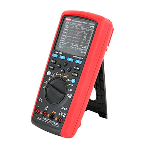
Model UT181A: OPERATING MANUAL V. Meter Structure (see Figure 1) Case Function Keys Rotary Switch Input Terminals Figure 1... -
Page 8: Vi.lcd Display
Model UT181A: OPERATING MANUAL VI .LCD Display (see Figure 2) No. Function Description Indicates auxiliary functions under current Label of Function Keys measuring interface Analog display of input signals Simulation Bar Minus Sign Indicates minus reading Lightning Symbol Danger- High Voltage... -
Page 9: Vii.keys, Rotary Switch And Input Terminals
Model UT181A: OPERATING MANUAL VII. Keys, Rotary Switch and Input Terminals ( 1 ) K e y s The 14 keys on the meter are used to activate the selected features of extensible rotary switch, browse menus or control the meter power. - Page 10 Model UT181A: OPERATING MANUAL Measurement of frequency, duty cycle and pulse width Hz% ms-Pulse Measurement ofµA in AC, DC and AC+DC µA全 Measurement of mA in AC, DC and AC+DC 今 Measurement of ampere in AC, DC and AC+DC A今...
-
Page 11: Viii.technical Index
Model UT181A: OPERATING MANUAL VIII. Technical Index 1. General Specifications The maximum voltage between any terminal and ground: 1000 V The fuse protection of mA orµA input terminals: 0. 8A H 1 OOOV Fuse Type 6X32mm A The fuse protection of A input terminals: 1 OA H 1 OOOV Fuse Type 1 OX38mm Max. -
Page 12: Electrical Specifications
Model UT181A: OPERATING MANUAL 2. Electrical Specifications Accuracy: 士( % Reading + Digits), one-year calibration period; If the temperature variation of environment ° reaches 士S C, the accuracy can be adopted after two hours. T he accuracy can be adopted after two hours when the battery charging is completed. - Page 13 Model UT181A: OPERATING MANUAL (2) DC Voltage Range Accuracy Tolerance: 士(%Reading+ Digits ) Resolution 60mV 0.001mV 土(0.025%+20) 600mV 0.01mV 0.0001V 士(0.025%+5) 0.001V 600V 0.01V 士(0.03%+5) 1000V 0.1V • Input impedance: About 1 OMO • Overload protection: 1 OOOV • Relative mode (REL ) is required to compensate bias voltage for 60mV...
- Page 14 Model UT181A: OPERATING MANUAL • Input impedance: About 1 OMO 产 • Overloa� rotection: 1,000V • Display: rue virtual value for 10% to 100% of the range. (4) AC Current Range Accuracy Tolerance: 士 ( %Reading+ Digits ) Resolution 45-lkHz 1 k-10kHz 600µA...
- Page 15 Model UT181A: OPERATING MANUAL (5) DC Current Range Accuracy Tolerance: 士 ( %Reading+ Digits ) Resolution 600µA 0.01µA 土(0.08%+20) 6000µA 0.1µA 士(0.08%+10) 士(0.08%+20) 60mA 0.001mA 士(0.15%+10) 600mA 0.01 mA 土(0.5%+10) 0.001 A • Overload protection: µAmA range: 0. 8A H 1 OOOV Fuse Type <I> 6x32 mm 10 A range: 1 OA H 1 OOOV Fuse Type <1>1 Ox38mm...
- Page 16 Model UT181A: OPERATING MANUAL • Display: True virtual value for 10% to 100% of the range. • Overload protection: µAmA range: 0. 8A H 1 OOOV Fuse Type <I> 6x32 mm 10 A range: 1 OA H 1 OOOV Fuse Type <1>1 Ox38mm •...
- Page 17 Model UT181A: OPERATING MANUAL (9) Capacitance Range Resolution Accuracy Tolerance: 土 ( %Reading+ Digits ) 土(3%+10) 0.001 nF 60nF 0.01 nF 土(2.5%+5) 600nF O.lnF 6µF 0.001µF 土(2%+5) 60µF 0.01µF 600µF 0.1µF l µF 土(5%+5) 10µF Not specified 60mF • Overload protection: 1000V •...
- Page 18 Model UT181A: OPERATING MANUAL (11) Fr e quency Range Accuracy Resolution 土(0.02%+8) 60Hz 0.001 Hz 600Hz 0.01 Hz 6kHz 0.0001 kHz 60kHz 0.001 kHz 士(0.01%+5) 600kHz 0.01 kHz 6MHz 0.0001MHz 60MHz 0.001MHz • Overload protection: 1000V • Input amplitude: 1 OHz-30MHz: 600mv:::;:; a郊OVrm. Greater than 30MHz: Not specified...
- Page 19 Model UT181A: OPERATING MANUAL (14) Continuity Test Remark Range Resolution Open circuit voltage is around 3V; when the buzzer selects short circuit for sound warning, the resolution is less than 100. The buzzer continuously sounds, the • •>) son. 0.010 resolution is greater than The buzzer does not sound.
-
Page 20: Ix.measurement Operation
Model UT181A: OPERATING MANUAL IX. Measurement Operation 1. Meter Power Control 1) Manually start up and shut down the meter power. When the meter is off, long press to start the meter. When the meter is on, long press to shut it off. -
Page 21: Meter Settings
Model UT181A: OPERATING MANUAL 5) Power Saving Mode Set the control time of automatic reduction for backlight brightness and off time for display via the meter menu bar "AUT O POWER SAVE" to enter power-saving mode. Please refer to the detailed description about the meter settings. - Page 22 Model UT181A: OPERATING MANUAL Description Menu Item Set Value Control time of automatic reduction Brightness Down ON: 1-60 Min OFF: T his function is disabled for backlight brightness Display Off Off time of display ON: 1-60 Min OFF: T his function is disabled...
-
Page 23: Ac Voltag
Model UT181A: OPERATING MANUAL 3. AC Voltage For crest of 1.4-2.0, the accuracy shall be added 1.0%. 1) Insert the red test lead into the V terminal and the black For crest of 2.0-2.5, the accuracy shall be added 2.5%. -
Page 24: Ac And Dc Current
Model UT181A: OPERATING MANUAL 5. AC and DC Current 4) Press the function key MENU (Menu) to enter one menu item in which basic DC voltage measurement can be modified. 1) Insert the red test lead into theµAmA or A terminal and the Press the cursor keys 器... - Page 25 Model UT181A: OPERATING MANUAL • After completing all the measuring operations, disconnect the connection between the test leads and the circuit under test. AC/DC AC/DC AC/DC 二 :::i-, -•HI-七 -•HI--=, , -•HI-七 二 :::i-, 「 「 Figure 7...
-
Page 26: Resistance
Model UT181A: OPERATING MANUAL 6. Resistance • When measuring the resistance above 1 MO, the readings require a few seconds to be stable. It is normal for the 1) Insert the red test lead into the O terminal and the black measurement of high resistance. -
Page 27: Conductance
Model UT181A: OPERATING MANUAL 7. Conductance 3) Directly read the measured capacitance value on the display . 1) Insert the red test lead into the terminal and the black .& Attention: test lead into the COM terminal. • If the measured capacitance shorts or capacitance value 2) Set the rotary switch to the measurement Ons-,, 1 . -
Page 28: Continuity Test
Model UT181A: OPERATING MANUAL short circuit for alarm sound, the measured resistance between both ends <100, the buzzer continuously sound > 500. The buzzer does not sound. If pressing the key OPEN (Menu), then the buzzer selects open circuit for alarm sound, the measured resistance between both ends>... - Page 29 Model UT181A: OPERATING MANUAL 3) Press the function key MENU(Menu) to enter menu items. If pressing the key ALARM, the buzzer starts up. It will beep briefly for the normal semiconductor junction; If the semiconductor junction shorts out, it will beep continuously.
-
Page 30: Frequency/Duty Cycle Measurement/Pulse Width
Model UT181A: OPERATING MANUAL 11. Frequency/Duty Cycle Measurement /Pulse 心 ttention: Width • Simulation bar displays the frequency of the measured 1) Insert the red test lead into the V terminal and the black signal for duty cycle and pulse width. -
Page 32: Dbv
Model UT181A: OPERATING MANUAL cursor keys 0 象 0 to select the menu item dBm. A reference • In the LPF measuring mode, the meter will turn to manual impedance (resistance) must be used for the measurement mode. Press the key RANGE to select a range. When the of dBm to calculate dB value on the basis of 1 mW. -
Page 33: Relative Value
Model UT181A: OPERATING MANUAL 17. Relative value e<Value Press the function key MENU (Menu) to enter a next e<Value interface, press the function key REL (Menu) to enter e>Value the measuring mode of relative values, then press the e>Value function key REL (Menu) to activate the measurement... -
Page 34: Recording Measured Data
Model UT181A: OPERATING MANUAL After completing the settings, press the function key confirm. To cancel the operation, press the function key START (Menu) to start the measurement of compare NO(Menu). mode. Press the function key EXIT (Menu) to exit the... - Page 35 Model UT181A: OPERATING MANUAL • Max Duration Indicat s th maximum tim continous ding 一 compl ting th ttings, p ss th function k START (M nu) to sta t a continous ding as shown in Figu REC shows on th...
- Page 36 Model UT181A: OPERATING MANUAL 5) View Record Press the function key(Menu) to view the information on record events as shown in Figure 14. T he basic display information is in the following table. Information Description Name: MEC 01 Name Name of record event...
- Page 37 Model UT181A: OPERATING MANUAL Press the function key PREV (Menu) to display basic information No. Description on the previous record. Press the function key NEXT (Menu) Measured value corresponding to cursor @ to display basic information on the next record. Press the Date and time for measurement corresponding to cursor @...
-
Page 38: Communication
Model UT181A: OPERATING MANUAL 罚 X. Maintenance and Repair 21.Communication 1. General Maintenance and Repair Regularly clean the meter case with damp cloth and mild detergent. Do not use abrasives, isopropyl alcohol or solvents. Dirt or moisture on the terminals can affect readings but also enable the warning function mistakenly due to mis-insertion. -
Page 39: Replacing Fuss
Model UT181A: OPERATING MANUAL 3. Repalcing Fuse inserted too deeply in the terminal of current input. Draw out the test lead a little until the error message disappears Inspect or replace the meter fuse as shown in Figure 18 and OL (overload) or resistance reading appears on the according to the following steps: display. -
Page 40: Battery Charge
Model UT181A: OPERATING MANUAL 4. Battery charge When the indicator of battery level in upper right corner is less than 5% of full capacity, the meter should be immediately charged, otherwise it will affect the measurement accuracy. As shown in Figure 19, set the rotary switch to 谥,the string "Please plug in AC adapter!"... - Page 41 Model UT181A: OPERATING MANUAL 一 UNI-TREND TECHNOLOGY (CHINA) CO., LTD. No6, Gong Ye Bei 1st Road, Songshan Lake National High-Tech Industrial Development Zone, Dongguan City, Guangdong Province, China Tel: (86-769) 8572 3888 http://www.uni-trend.com...
Need help?
Do you have a question about the UT181A and is the answer not in the manual?
Questions and answers