Table of Contents
Advertisement
Quick Links
Advertisement
Table of Contents

Related Manuals for UNI-T UTE9811+


Summary of Contents for UNI-T UTE9811+
- Page 1 User’s Manual UTE9811+ Smart Digital Power Meter...
-
Page 2: Copyright Information
If the product is shipped domestically to the location of the UNI-T service center, UNI-T shall pay the return shipping fee. If the product is sent to any other location, the customer shall be responsible for all shipping, duties, taxes, and any other expenses. -
Page 3: Safety Instructions
This warranty is written by UNI-T for this product, and it is used to substitute any other express or implied warranties. UNI-T and its distributors do not offer any implied warranties for merchant ability or applicability purposes. -
Page 4: Environmental Condition
User’s Manual UTE9811+ Smart Digital Power Met er 6. Instrument grounding:To prevent the risk of electric shock, please connect the power ground wire. 7. Do not install substitutes or perform unauthorized changes; do not use the instrument when the outer shell opened or looseness. -
Page 5: Chapter 1 Inspection And Installment
UTE9811+ Smart Digital Power Met er Chapter 1 Inspection and Installment 1.1 Check Packing List Check with packing list to confirm that accessories has no loss or abnormal. If there have any problem, please contact with UNI-T distributor or manufacture. Components Quantity Remark... - Page 6 User’s Manual UTE9811+ Smart Digital Power Met er 2. Testing Position 3. Remove Hand Shank 4. Lift Position Instruments.uni-trend.com 6 / 40...
-
Page 7: Chapter 2 Product Introduction
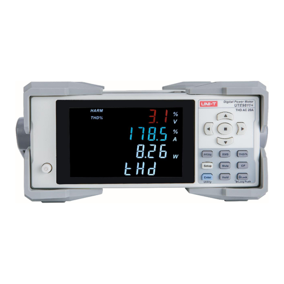
User’s Manual UTE9811+ Smart Digital Power Met er Chapter 2 Product Introduction 2.1 Product Overview UTE9811+ smart digital power meter is an economic and portable measuring instrument. It is a multi- functional measuring instrument which integrating voltage, current, power, power factor and harmonic wave. The products is widely used in production, testing, evaluation and scientific research and multi-field. -
Page 8: Technical Index
User’s Manual UTE9811+ Smart Digital Power Met er 2.2 Technical Index Note: * f represent the frequency of input signal in the below table. Model UTE9811+ Display VA broken code display, 5 digits,four windows Display Update Rate 0.1S, 0.25S, 0.5S, 1S, 2S, 5S Measuring Object V,A,W,PF/HZ/THD/CF Measuring Mode... - Page 9 User’s Manual UTE9811+ Smart Digital Power Met er Current Range Irms exceeds the measuring range about 110 %( CF < 2 ) Increasing Current Range Irms is less than the lower part range about 60 %( CF < 2 ) Decreasing Harmonic Analysis Times 1~50...
- Page 10 User’s Manual UTE9811+ Smart Digital Power Met er Precision Environment 18 ℃ ~28 ℃, 30%~75%RH (28 ℃ < operating temperature <18 ℃ (when in 18 ℃ , it needs to add temperature coefficient): reading of 0.05%/ ℃) Storage Temperature -10 ℃ ~50 ℃, non-condensing below 80% RH Operating Altitude ≤2000 meters General Characteristic...
-
Page 11: Front Panel
User’s Manual UTE9811+ Smart Digital Power Met er 2.3 Front Panel The front panel and function of UTE9811+, as shown in the following figure. 2.3.1 Key function on the front panel Key Function Symbol Description Press one time to turn “ON”, the power source is enabled, press it again Power Switch to turn “OFF”, the power source is disabled. - Page 12 User’s Manual UTE9811+ Smart Digital Power Met er Enter Setup menu, this menu is to editing the configuration data of Setup Key measurement, alarm and communication. The beeper can be mute when over the limit (mute alarm). Press the key Mute Key to activate mute key and the indicator will be illuminated;...
- Page 13 User’s Manual UTE9811+ Smart Digital Power Met er 2.4 Digital and Character Display The data display format of data display window is nixie tube. Due to the limitation of the format, special symbols are needed to represent each character, as shown in the following figure. 2.5 Rear Panel The rear panel and function of UTE9811+, as shown in the following figure and table.
-
Page 14: Chapter 3 Operating Preparation And Measurement
User’s Manual UTE9811+ Smart Digital Power Met er Under test input terminal /SOURCE terminal,it usually used to connect to the output port of AC power. Three-wire power socket and fuse Ground terminal RS232/RS485 communication interface Chapter 3 Operating Preparation and Measurement Display 3.1 Operating Preparation 3.1.1 Connecting Power Cable... - Page 15 User’s Manual UTE9811+ Smart Digital Power Met er at the load end. Notes: 1)When measuring large current/voltage or the current includes high frequency, it should pay attention to possible mutual interference and noise problems when wiring. 2)The lead wire should as short as possible. 3)Use heavy gauge wire as can as possible when measuring current.
-
Page 16: Measurement Display
User’s Manual UTE9811+ Smart Digital Power Met er 3.2 Measurement Display 3.2.1 Window Display UTE9811+ has four display windows, it can display different measurement value at the same time, as shown in the following table. Window Display Name Measurement Range Voltage (volt)... - Page 17 User’s Manual UTE9811+ Smart Digital Power Met er 3.2.4 Alarm for Auto Range Switching UTE9811+ supports auto range, it can adjust the range according to the size of input signal. The adjustment interface as shown in the following figure. Window 2: the current voltage range, “600V”,“300V” , “150V” , “75V”. Window 4: the currently current range, “20A”...
- Page 18 User’s Manual UTE9811+ Smart Digital Power Met er total RMS of harmonic display interface, please select the appropriate interface. The following figure is TRMS display interface. Window 1: the measured value of voltage, the unit is V. Window 2: the measured value of current, the unit is A. Window 3: the measured value of power, the unit is W.
- Page 19 User’s Manual UTE9811+ Smart Digital Power Met er 3.3.3 Total RMS of Harmonic Press【RMS】key to enter the total RMS of harmonic display interface. Notes: If press【RMS】key multiple times, the system switches between the TRMS display interface and the total RMS of harmonic display interface, please select the appropriate interface. The following figure is the total RMS of harmonic display interface.
- Page 20 User’s Manual UTE9811+ Smart Digital Power Met er 【↑】or【↓】key supports continuous press function, long press the two keys to quickly switch the display item. • When window 4 displays“tHD”, Window 1: the measured value of the voltage total harmonic distortion,the unit is V. Window 2: the measured value of the current total harmonic distortion,the unit is A.
- Page 21 User’s Manual UTE9811+ Smart Digital Power Met er represents the currently selected harmonic times. The display item of window 4 can switch by【↑】or【↓】. 【↑】or【↓】key supports continuous press function, long press the two keys to quickly switch the display item. •When window 4 displays“tHD”, Window 1: voltage total harmonic distortion factor,the unit is %.
-
Page 22: Chapter 4 Measurement
User’s Manual UTE9811+ Smart Digital Power Met er Chapter 4 Measurement 4.1 Average Setting ·Step 1. Press【SETUP】key to enter SETUP menu,press【←】or【→】key to select submenu“AVG”as shown in the following figure; 2. Press【ENTER】key to enter the next option, and the press【↑】or【↓】key to select OFF, 8, 16, 32 or 64;... - Page 23 User’s Manual UTE9811+ Smart Digital Power Met er 4.5 Data Update Cycle ·Step 1. Press【SETUP】key to enter SETUP menu,press【←】or【→】key to select submenu“u.rate”as shown in the following figure; 2. Press【ENTER】key to enter the next option, and the press【↑】or【↓】key to select 0.1, 0.25, 0.5, 1, 2 or 5;...
-
Page 24: Measurement Range
User’s Manual UTE9811+ Smart Digital Power Met er 4.3 Measurement Range 4.3.1 Manual Range If the measurement range is set to manual range, the selected range will not be change even if the size of input signal changes. The manual range can select from the following options. Voltage range:600V, 300V, 150V, 75V. -
Page 25: Chapter 5 Alarm
User’s Manual UTE9811+ Smart Digital Power Met er Chapter 5 Alarm 5.1 Upper/Lower Limit of Current and Power ·Step Press【SETUP】key to enter SETUP menu,press【←】or【→】key to select one of submenu“A-Hi”,“A-Lo” , “P-Hi” or“P-Lo” as shown in the following figure; 2. Press【ENTER】key to enter numerical value editing state, press【 ↑】 【↓】 【→】 【←】 【 】... -
Page 26: Alarm Function
User’s Manual UTE9811+ Smart Digital Power Met er 5.2 Alarm Delay ·Step 1. Press【SETUP】key to enter SETUP menu,press【←】or【→】key to select submenu “tiME” as shown in the following figure; 2. Press【ENTER】key to enter numerical value editing state, press【 ↑】【↓】【→】【←】 key to edit the numerical value;... -
Page 27: Chapter 6 Communication
User’s Manual UTE9811+ Smart Digital Power Met er Chapter 6 Communication 6.1 Communication Command ·Step 1. Press【SETUP】key to enter SETUP menu,press【←】or【→】key to select submenu “CoMAd”as shown in the following figure; 2. Press【ENTER】 key to enter the next option, and the press【 ↑】 or【 ↓】 key to select “SCPI” or “... -
Page 28: Modbus Communication Address
User’s Manual UTE9811+ Smart Digital Power Met er 4. Press【←】or【→】key to select other submenu, or press【SETUP】key to exit SETUP menu. ·Explanation UTE9811+ supports RS232 and RS485 interface,both interfaces have the same baud rate, so it can be set by the method in this section. 6.3 Modbus Communication Address ·Step 1. -
Page 29: Chapter 7 System Function
User’s Manual UTE9811+ Smart Digital Power Met er Chapter 7 System Function 7.1 Initialization ·Step 1. Long press【ENTER】(Utility) key to enter Utility menu, and the submenu is “init” as shown in the following figure; 2. Press【ENTER】key to enter the next option, and the press【↑】or【↓】key to select NO or YES; 3. -
Page 30: View Software Information
User’s Manual UTE9811+ Smart Digital Power Met er 7.2 View Software Information ·Step 1. Long press 【 ENTER】 (Utility) key to enter Utility menu, press 【 ←】 or 【 →】 key to select submenu“Ver” as shown in the following figure; 2. -
Page 31: Firmware Update
User’s Manual UTE9811+ Smart Digital Power Met er ·Explanation “norm”represents that the instrument is only support normal function. “High”represents that the instrument supports other auxiliary function except only support normal function. The default is “norm”. UTE9811+ Auxiliary Function. The auxiliary function can refer to After the user’s grade is complete, reboot the instrument for the setting to take effect. - Page 32 User’s Manual UTE9811+ Smart Digital Power Met er 7.5 Calibration ·Step 1. Long press【ENTER】(Utility) key to enter Utility menu, press【←】or【→】key to select submenu “CALib” as shown in the following figure; 2. Press【ENTER】key to enter secret code editing, press【 ↑】 【↓】 【→】 【←】key to edit secret code;...
-
Page 33: Chapter 8 Communication Interface
User’s Manual UTE9811+ Smart Digital Power Met er Chapter 8 Communication Interface 8.1 RS232 and RS485 Interface UTE9811+ has standard RS232 and RS485 communication interface,PC or PLC can remote control UTE9811+ via SCPI or Modbus command. ·The Definition of Pin UTE9811+ communication interface is DB9 female head, the definition of pin as shown in the following figure. - Page 34 User’s Manual UTE9811+ Smart Digital Power Met er 8.2.2 PC connect to a single UTE9811+ via RS485 · The number in block diagram represents the pin number of DB9 interface. · Use direct serial port line to connect PC and the RS232 to RS485 convertor. ·...
-
Page 35: Chapter 9 Storage And Calibration
User’s Manual UTE9811+ Smart Digital Power Met er Chapter 9 Storage and Calibration 9.1 Notice Matters for Storage 9.1.1 The instrument should be stored in the environment which specified in the user manual, refer to Chapter 2.2 storage temperature in Technical Index table. Do not store the instrument in a place with high temperature, high humidity, temperature rapid change or easy condensation. - Page 36 User’s Manual UTE9811+ Smart Digital Power Met er 9.3 Notice Matters for Calibration Verification and Calibration The precision of standard meter should over a grade than measured meter, standard source should be stable. All the instrument power on 15 minute and wait it to stabilize, and then slowly adjust the output voltage or current of the standard AC source.
-
Page 37: Chapter 10 Optional And Fuse
User’s Manual UTE9811+ Smart Digital Power Met er Chapter 10 Optional and Fuse 10.1 Optional Testing Wire Uni-trend company provides optional testing wire, there are three model UTE-L16A, UTE-L10A, UTE-L16C, as shown in the following figure. User can purchase one or multiple testing wires according your own needs. The following table is match solution for user to reference. - Page 38 User’s Manual UTE9811+ Smart Digital Power Met er Warning:Before connect with circuit, please make sure the power is cut off to prevent from electric shock. 10.2 Specification of Fuse This instrument has 1 spare fuse stored in the fuse box. If the fuse was burned out, replace the fuse as the follow steps.
-
Page 39: Appendix 1 Symbol And Formula Of Measurement
User’s Manual UTE9811+ Smart Digital Power Met er Appendix 1 Symbol and Formula of Measurement Normal Measurement Measurement Function [Unit] Operation Formula Explanation Voltage U [V] u(n) represents instantaneous value of voltage; Current I [A] i(n) represents instantaneous value of current; Active power P [W] N represents ADC sampling time within the measurement range. - Page 40 User’s Manual UTE9811+ Smart Digital Power Met er Total RMS current of 1~50 times I [V] Total RMS active power of 1~50 times P [W] Voltage harmonic distortion factor Uhdf(k) [%] Current harmonic distortion factor Ihdf(k) [%] Voltage total harmonic ...
Need help?
Do you have a question about the UTE9811+ and is the answer not in the manual?
Questions and answers