Table of Contents
Advertisement
Quick Links
Advertisement
Table of Contents

Related Manuals for UNI-T UTE9800+ Series


Summary of Contents for UNI-T UTE9800+ Series
- Page 1 User’s Manual UTE9800+ Series Smart Digital Power Meter...
-
Page 2: Copyright Information
If the product is shipped domestically to the location of the UNI-T service center, UNI-T shall pay the return shipping fee. If the product is sent to any other location, the customer shall be responsible for all shipping, duties, taxes, and any other expenses. -
Page 3: Safety Instructions
This warranty is written by UNI-T for this product, and it is used to substitute any other express or implied warranties. UNI-T and its distributors do not offer any implied warranties for merchant ability or applicability purposes. - Page 4 Environmental Condition UTE9800+ series digital power meter can only use indoors and non-condensing area, the general environmental requirements shown as below table. Environmental Condition 5℃~40℃,20%~80%RH(non-condensing)...
-
Page 5: Chapter 1 Inspection And Installment
User’s Manual UTE9800+ Series Smart Digital Power Meter Chapter 1 Inspection and Installment 1.1 Check Packing List Check with packing list to confirm that accessories has no loss or abnormal. If there have any problem, please contact with UNI-T distributor or manufacture. -
Page 6: Chapter 2 Product Introduction
The product is widely used in production, testing, evaluation and scientific research and multi-field. UTE9800+ series include three models: UTE9802+, UTE9806+, and UTE9811+. It adopts high speed CPU for data processing, the sampling resistance of voltage and current are all use low temperature drift resistor, therefore, the stability and accuracy of measurement data are guaranteed. -
Page 7: Technical Index
User’s Manual UTE9800+ Series Smart Digital Power Meter 2.2 Technical Index * f represent the frequency of input signal in the below table. Model UTE9802+ UTE9806+ UTE9811+ Display VA broken code display, 5 digits , four windows Display Update 0.1S, 0.25S, 0.5S, 1S, 2S, 5S... - Page 8 User’s Manual UTE9800+ Series Smart Digital Power Meter g Range Power 1W~12kW 1W~6000W 1W~12kW Range DC : ±(0.4% reading+ 0.1% 40Hz≤f≤66Hz : ±(0.4% reading+ range+1 character ) 0.1% range+1 character ) 40Hz≤f≤70Hz : ±(0.4% Accurac 40Hz≤f≤66Hz : ±(0.4% reading+ 66Hz < f≤400Hz : ±(0.3% reading+ 0.2% range+1...
- Page 9 User’s Manual UTE9800+ Series Smart Digital Power Meter Maximu Allowed 1000V, 40A (1 min) 1000V, 20A (1 min) 1000V, 40A (1 min) Input Instant Input Voltage about 2 M Ω , Current is Voltage about 2 M Ω , Current is Voltage about 2 M Ω...
-
Page 10: Front Panel
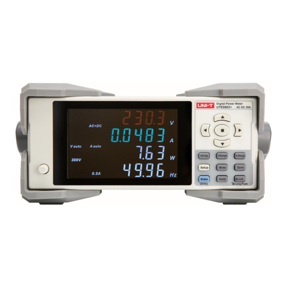
User’s Manual UTE9800+ Series Smart Digital Power Meter Storage Temper -10℃~50℃ , non-condensing below 80% RH ature Operati ≤2000 meters Altitude General Characteristic Color Gray Weight 3.3kg 3.2kg 3.2kg Size 214mm×88mm×340mm Standar Specialized power cable x1 ; RS232 serial port line X1... - Page 11 User’s Manual UTE9800+ Series Smart Digital Power Meter Figure 2.3.1 UTE9802+ Front Panel Power Switch Display Keys Description of UTE9802+ keys Symbol Description Function Power Press one time to turn “ON”, the power source is enabled, press it again to turn “OFF”, Switch the power source is disabled.
- Page 12 User’s Manual UTE9800+ Series Smart Digital Power Meter 2.3.2 UTE9806+ Front Panel and Keys The front panel of UTE9806+ is as shown in the figure 2.3.2. Figure 2.3.2 UTE9806+ Front Panel Power Switch Display Keys Description of UTE9806+ keys Key Function...
- Page 13 User’s Manual UTE9800+ Series Smart Digital Power Meter Press Setup key to enter the setting menu of average filter and display Setup Key Setup the update cycle. Secondary function auxiliary key : Shift + A to enter voltage range setting;Shift + B to enter current range setting;Shift + Setup to enter...
- Page 14 User’s Manual UTE9800+ Series Smart Digital Power Meter Number editing: Use up, down key to increase or decrease the numerical value. For description, use“▲”,“▼”to indicate the two keys in the manual. Decimal Point Number editing: To move decimal point Hold Display Hold Data hold key, when the key is activated, it will keep display the current data.
- Page 15 User’s Manual UTE9800+ Series Smart Digital Power Meter 2.4.1 UTE9802+ Display and Symbol Display and Symbol Description Four display windows; Display measurement data: The display screen can display V (voltage), A (current), W (power), PF (power factor)/Hz (frequency) at the same time.
- Page 16 User’s Manual UTE9800+ Series Smart Digital Power Meter The currently current range, when it displays A auto, it is auto range. 2.4.2 UTE9806+ Display and Symbol Display and Symbol Description A,B,C,D four windows can be simultaneous measurement Window A can measure V, A, W, VA;...
-
Page 17: Rear Panel
User’s Manual UTE9800+ Series Smart Digital Power Meter The measured parameter in the current window is voltage frequency. The measured parameter in the current window is current frequency. 2.4.3 UTE9811+ Display and Symbol Display and Symbol Description Four display windows;... -
Page 18: Chapter 3 Operating Preparation And Measurement Display
User’s Manual UTE9800+ Series Smart Digital Power Meter The rear panel of UTE9806+ is as shown in the following figure. The function description of UTE9802+/UTE9806+/UTE9811+ rear panel is as shown in the following table. Picture of parts Description Under test load/LOAD terminal, it usually used to connect to the input port of the product to be test. - Page 19 User’s Manual UTE9800+ Series Smart Digital Power Meter Warning: Please make sure that the power supply voltage matches the supply voltage before turning on the power supply, otherwise the instrument will be burned out. Notes: The instrument should be used under the recommended working conditions. Never use the instrument in a place where have flammable or explosive materials, it may cause safety injuries.
- Page 20 User’s Manual UTE9800+ Series Smart Digital Power Meter required measurement value from the display on the front panel of the instrument after the load has been working stably. Notes: The instrument should be preheated for 30 minutes before entering the stable state. After cutting off the instrument power, it should wait for more than 5 seconds before powering it on again.
-
Page 21: Measurement Display
User’s Manual UTE9800+ Series Smart Digital Power Meter Baud Rate:9600 Communication Address 000 Communication Protocol:SCPI 3.2 Measurement Display 3.2.1 Window Display UTE9802+/UTE9811+ has four display windows, it can display different measurement value at the same time, as shown in the following table. - Page 22 User’s Manual UTE9800+ Series Smart Digital Power Meter Para- V pk A pk V Hz A Hz Meter A/mA (Apparent (Current (Active (Power (Voltage (Current (Voltage (Voltage) (Current) Power) Frequency) Power) Factor) Peak) Peak) Frequency) Window √ √ √ √...
- Page 23 User’s Manual UTE9800+ Series Smart Digital Power Meter UTE9811+ supports auto range; it can adjust the range according to the size of input signal. The adjustment interface as shown in the following figure. Window 2: the current voltage range, “600V”,“300V” , “150V” , “75V”.
- Page 24 User’s Manual UTE9800+ Series Smart Digital Power Meter Window 1: the measured value of voltage, the unit is V. Window 2: the measured value of current, the unit is A. Window 3: the measured value of power, the unit is W.
- Page 25 User’s Manual UTE9800+ Series Smart Digital Power Meter Window 1: the total RMS voltage (operation value) of 1~50 times,the unit is V. Window 2: the total RMS current (operation value) of 1~50 times,the unit is A. Window 3: the total RMS active power (operation value) of 1~50 times, the unit is W.
- Page 26 User’s Manual UTE9800+ Series Smart Digital Power Meter •When window 4 displays“or01”~“or50”, Window 1: the voltage measured value of the current harmonic times,the unit is V. Window 2: the current measured value of the current harmonic times,the unit is A.
-
Page 27: Chapter 4 Measurement
User’s Manual UTE9800+ Series Smart Digital Power Meter Window 2: current distortion factor of the current harmonic times, the unit is %. Window 3: the total RMS power (operation value) of 1~50 times,the unit is W. •When no voltage signal is input or voltage frequency is over the range, Window 1, 2, 3 displays“-----”. - Page 28 User’s Manual UTE9800+ Series Smart Digital Power Meter Upk exceeds measurement range about 170%. Voltage Range Decreasing The voltage range will decrease when any one of the following condition is met. Urms is less than the lower part range about 80%.
- Page 29 User’s Manual UTE9800+ Series Smart Digital Power Meter 1. Press the secondary auxiliary key 【 Shift】 in the measurement interface, and press 【 B/A.Range】 key to enter the setting interface of current range (the display is the current range) as shown in the following figure;...
- Page 30 User’s Manual UTE9800+ Series Smart Digital Power Meter 4.3.2 Auto Range If the measurement range is set to auto range, the instrument will synchronous switch range according to the size of input signal. UTE9811+ is only supports auto range in normal mode.
- Page 31 User’s Manual UTE9800+ Series Smart Digital Power Meter TRMS TRMS ACDC(AC+DC) AC component AC component Simple average Simple average Theoretical Equation ACDC (AC+DC): Select this mode to display the TRMS value of the voltage and current. f(t): input signal ...
- Page 32 User’s Manual UTE9800+ Series Smart Digital Power Meter ·Explanation OFF represents the average function is disabled. 8, 16, 32, 64 represents the average function is enabled and the number of average. 4.5.2 UTE9806+ Average Steps 1. Press【SETUP】key to enter SETUP menu,press【▲】or【▼】key to select submenu“AVG”as shown in the following figure;...
-
Page 33: Chapter 5 Alarm
User’s Manual UTE9800+ Series Smart Digital Power Meter : Display the numerical value after linear average of m item data from the n-(m-1) to the n th order : The numerical value data of n-(m-1) order ( ) : The numerical value data of n-2 order... - Page 34 User’s Manual UTE9800+ Series Smart Digital Power Meter “P-Hi” or“P-Lo” as shown in the following figure; 2. Press 【 ENTER 】 key to enter numerical value editing state, press 【 ▲ 】【 ▼ 】【 】【 】【 】 key to edit the numerical value ;...
-
Page 35: Alarm Function
User’s Manual UTE9800+ Series Smart Digital Power Meter Explanation The unit of alarm delay is S,the range can set to 0~99.9. 5.3 Alarm Function 5.3.1 Turn on/off Alarm Function of UTE9802+/UTE9811+ When the upper/lower limit is different but as “0”, it represents the alarm function is enabled. - Page 36 User’s Manual UTE9800+ Series Smart Digital Power Meter 4. Press【OK】key to save the currently selected and return to previous menu. Explanation ON represent the alarm function is enabled. OFF represent the alarm function is disabled. 5.4 Alarm Parameter (UTE9806+ only) ·5.4.1 Set Voltage, Current, Power and Power Factor...
- Page 37 User’s Manual UTE9800+ Series Smart Digital Power Meter 9. Press 【▲】 , 【 ▼】 , 【 】 , 【 】 key to edit data and press 【Shift】 + 【Hold/·】 key can move the decimal point from left to right. 10. Press【OK】key to finish the setting and return to the previous menu.
-
Page 38: Chapter 6 Communication
User’s Manual UTE9800+ Series Smart Digital Power Meter triggered; 2. Only set the lower limit, if the measured value is less than the upper limit D----alarm will be triggered; 3. Set the upper and lower limit, if the measured value is greater than the upper limit U or the measured value is less than the upper limit D----alarm will be triggered;... - Page 39 6. Press【Hold】key to return to previous menu. ·Explanation UTE9802+/UTE9806+/UTE9811+ supports SCPI and Modbus communication command. “ ” or“ ” represents“Modbus” communication command. Modbus is only support RTU mode. The detailed command can refer to UTE9800+ Series Smart Digital Power Meter –Programming Manual Instruments.uni-trend.com 39 / 55...
- Page 40 User’s Manual UTE9800+ Series Smart Digital Power Meter 6.2 Baud Rate and Modbus Communication Address 6.2.1 Baud Rate Setting of UTE9802+/UTE9811+ Steps 1. Press【SETUP】key to enter SETUP menu,press【 】or【 】key to select submenu“bAud” as shown in the following figure; 2. Press 【 ENTER 】 key to enter the next option, and the press 【 ▲ 】 or 【 ▼ 】 key to select 4800, 9600, 19200, 38400, 57600 or 115200 ;...
- Page 41 User’s Manual UTE9800+ Series Smart Digital Power Meter Explanation Only when the communication command sets to Modbus, submenu“Addr” can display. The setting method of communication command can refer to section 6.1 The Modbus communication address range of UTE9802+ is 1-99.
-
Page 42: Chapter 7 System Function
User’s Manual UTE9800+ Series Smart Digital Power Meter 6. Press【▲】,【▼】, 【 】,【 】key to edit address, the range is: 000~255; 7. Press【OK】key to save the currently selected and return to previous menu; 8. Press【Hold】key to return to previous menu. ·Explanation UTE9806+ supports RS232 and RS485 interface. - Page 43 User’s Manual UTE9800+ Series Smart Digital Power Meter Display Window 4 Display function:PF Date Update Cycle 0.25s Measurement Range Auto range Measurement Mode AC+DC Average Average function:OFF Upper/lower limit of current “0” and power Alarm Delay “0” *Notes: The item cannot be restore to the factory setting: the relevant setting of communication (communication command, baud rate, Modbus communication address).
-
Page 44: View Software Information
User’s Manual UTE9800+ Series Smart Digital Power Meter Voltage, Current, Active OFF,the upper and lower limit is“0” Power, Apparent Power, Power Factor 0 Input Alarm Blinking Alarm Delay Times “0010” Beep Beep times“0005” Data Hold Mute Key *Notes: The item cannot be restore to the factory setting: the relevant setting of communication (communication command, baud rate, Modbus communication address). - Page 45 User’s Manual UTE9800+ Series Smart Digital Power Meter 4. Press【Hold】key to exit Utility menu. Explanation “F – 1.00” represents firmware version;“H – 1.00” represents hardware version. 7.3.1 Firmware Update of UTE9802+/UTE9811+ Steps 1. Long press 【 ENTER】 (Utility) key to enter Utility menu, press 【 】 or 【 】 key to select submenu“boot”as shown in the following figure;...
- Page 46 User’s Manual UTE9800+ Series Smart Digital Power Meter 5. Press【OK】key to confirm the setting,if the secret code is correct, then it can enter firmware update interface. 6. If the upgrade is successful, it will automatically restart and enter the test interface. If the upgrade is not successful, the instrument will not start normally.
-
Page 47: Chapter 8 Communication Interface
Chapter 8 Communication Interface 8.1 RS232 and RS485 Interface UTE9800+ series has standard RS232 and RS485 communication interface , PC or PLC can remote control UTE9800+ series via SCPI or Modbus command. The Definition of Pin Instruments.uni-trend.com... - Page 48 User’s Manual UTE9800+ Series Smart Digital Power Meter UTE9800+ series communication interface is DB9 female head, the definition of pin as shown in the following figure. TXD(RS232) RXD(RS232) GND(RS232) A(RS485) B(RS485) Communication Setting Before operating communication, UTE9800+ series should match with the following parameters of the control host.
- Page 49 · Use direct serial port line to connect PC and the RS232 to RS485 convertor. · A , B port of the RS232 to RS485 convertor parallel connect to A , B port of multiple UTE9800+ series. · This connecting method is only support Modbus instruction. The baud rate of the PC must be the same as that of each UTE9800+ series, and the IP address of each UTE9800+ series must be different.
-
Page 50: Chapter 9 Storage And Calibration
User’s Manual UTE9800+ Series Smart Digital Power Meter Explanation For UTE9806+ or UTE9811+, the connection method is the same as UTE9802+. Chapter 9 Storage and Calibration 9.1 Notice Matters for Storage 9.1.1 The instrument should be stored in the environment which specified in the user manual, refer to Chapter 2.2 storage temperature in Technical Index table. - Page 51 User’s Manual UTE9800+ Series Smart Digital Power Meter (2)Make sure the display is away from noise interference. (3)Check whether the test wire is well connecting. (4)Check whether the wire is connect correctly. (5)Check whether data display is in the lock state.
-
Page 52: Chapter 10 Optional And Fuse
User’s Manual UTE9800+ Series Smart Digital Power Meter Ventilation Well-condition Sunlight Avoid direct sunlight Notes : The inspect equipment should meet the specifications of the regular metrological verification, measurement period is one year. Wiring scheme of verification and calibration is as shown in the following figure. - Page 53 User’s Manual UTE9800+ Series Smart Digital Power Meter Notes: The above figure is optional testing wire, not equipped with the instrument. It should purchase by your own. Match Solution of Testing Wire Match Component and Specification of Recommended Name Length...
- Page 54 User’s Manual UTE9800+ Series Smart Digital Power Meter 10.2 Specification of Fuse This instrument has 1 spare fuse stored in the fuse box. If the fuse was burned out, replace the fuse as the follow steps. 1) Pull out the power cable, use small screwdriver to take out the fuse box, as shown in the following figure.
-
Page 55: Appendix 1 Symbol And Formula Of Measurement
User’s Manual UTE9800+ Series Smart Digital Power Meter Appendix 1 Symbol and Formula of Measurement Measurement Function Operation Formula Explanation [Unit] Urms Voltage TRMS [V] Voltage DC Component [V] Voltage AC Component [V] ...
Need help?
Do you have a question about the UTE9800+ Series and is the answer not in the manual?
Questions and answers