Table of Contents
Advertisement
Quick Links
Advertisement
Table of Contents

Subscribe to Our Youtube Channel
Related Manuals for UNI-T UTE9802+


Summary of Contents for UNI-T UTE9802+
- Page 1 User’s Manual UTE9802+ Smart Digital Power Meter...
-
Page 2: Copyright Information
If the product is shipped domestically to the location of the UNI-T service center, UNI-T shall pay the return shipping fee. If the product is sent to any other location, the customer shall be responsible for all shipping, duties, taxes, and any other expenses. -
Page 3: Safety Instructions
This warranty is written by UNI-T for this product, and it is used to substitute any other express or implied warranties. UNI-T and its distributors do not offer any implied warranties for merchant ability or applicability purposes. -
Page 4: Environmental Condition
User’s Manual UTE9802+ Smart Digital Power Meter otherwise, it may cause unpredictable and serious consequences. 9. Avoid exposed circuits, do not touch exposed connectors and components after the power is turned on. 10. Use the appropriate fuse, only with the fuse type and rating indicator specified for this product. 11.Do not use the instrument that work abnormally;... -
Page 5: Chapter 1 Inspection And Installment
UTE9802+ Smart Digital Power Meter Chapter 1 Inspection and Installment 1.1 Check Packing List Check with packing list to confirm that accessories has no loss or abnormal. If there have any problem, please contact with UNI-T distributor or manufacture. Components Quantity Remark... - Page 6 User’s Manual UTE9802+ Smart Digital Power Meter 3. Remove Hand Shank 4. Lift Position Instruments.uni-trend.com 6 / 34...
-
Page 7: Chapter 2 Product Introduction
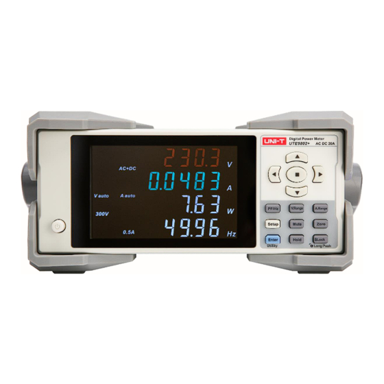
User’s Manual UTE9802+ Smart Digital Power Meter Chapter 2 Product Introduction 2.1 Product Overview UTE9802+ smart digital power meter is an economic and portable measuring instrument. It is a multi- functional measuring instrument which integrating voltage, current, power, power factor and frequency. The products is widely used in production, testing, evaluation and scientific research and multi-field. -
Page 8: Technical Index
User’s Manual UTE9802+ Smart Digital Power Meter 2.2 Technical Index * f represent the frequency of input signal in the below table. Model UTE9802+ Display VA broken code display, 5 digits,four windows Display Update Rate 0.1S, 0.25S, 0.5S, 1S, 2S, 5S V, A, W, PF/HZ Measuring Object AC, DC, AC+DC (T-RMS) - Page 9 User’s Manual UTE9802+ Smart Digital Power Meter Voltage Range Urms is less than the lower part range about 80% ( CF < 2) Decreasing Current Range Irms exceeds the measuring range about 110% ( CF < 2 ) Increasing Current Range Irms is less than the lower part range about 60% ( CF <...
-
Page 10: Front Panel
User’s Manual UTE9802+ Smart Digital Power Meter ≤2000 meters Operating Altitude General Characteristic Gray Color 3.3kg Weight 214mm×88mm×340mm Size Standard Accessories Specialized power cable x1;RS232 serial port line X1 UTE-L10A 10A three-pronged plug convert banana head plug connection cable x1 Optional Accessories UTE-L16C 16A connection cable with alligator clip x1 UTE-L16A 16A three-pronged plug convert banana head plug... - Page 11 User’s Manual UTE9802+ Smart Digital Power Meter Switch sub-menu:Use left, right key to select the sub-menu that need to be Left, Right edited. Number editing: Use left, right key to select the data bit that need to be edited. For description, use “←”,“→”to indicate the two keys in the manual. Menu editing: Use up, down key to select function item.
- Page 12 User’s Manual UTE9802+ Smart Digital Power Meter limit. A Hi:Measurement value of current is higher than the upper limit. A Lo:Measurement value of current is lower than the upper limit. P Hi:Measurement value of power is higher than the upper limit. P Lo:Measurement value of power is lower than the upper limit.
-
Page 13: Rear Panel
User’s Manual UTE9802+ Smart Digital Power Meter 2.5 Rear Panel The rear panel and function of UTE9802+, as shown in the following figure and table. Picture of parts Description Under test load/LOAD terminal, it usually used to connect to the input port of the product to be test. -
Page 14: Chapter 3 Operating Preparation And Measurement
User’s Manual UTE9802+ Smart Digital Power Meter Chapter 3 Operating Preparation and Measurement Display 3.1 Operating Preparation 3.1.1 Connecting Power Cable The operating voltage of the instrument is 100V~240V (50/60Hz), please make sure the power supply is within the rated voltage of this instrument, and make sure the instrument is well grounded. Warning: Please make sure that the power supply voltage matches the supply voltage before turning on the power supply, otherwise the instrument will be burned out. -
Page 15: Measurement Display
User’s Manual UTE9802+ Smart Digital Power Meter from the instrument housing as possible. 3.1.3 Turn ON/OFF Power Supply Turn on:Start self-check program when the instrument is enabled, the instrument will enter the measuring state if the check result is correct. Turn off:The upper/lower limit of current and power will be saved when the power has been turned off. - Page 16 User’s Manual UTE9802+ Smart Digital Power Meter The four window display as shown in the following figure. 3.2.2 Alarm for Over Range These situations will be regarded as over range. 1. The measured value of voltage and current exceeds 120% of the rated range; 2.
-
Page 17: Chapter 4 Measurement
User’s Manual UTE9802+ Smart Digital Power Meter Chapter 4 Measurement 4.1 Measurement Range 4.1.1 Voltage Range ·Step Press【V.Range】key to switch to voltage range. ·Explanation The range can set to Auto, 600V, 300V, 150V or 75V. The display interface will synchronous display the current selected voltage range. 4.1.2 Current Range ·Step Press【A.Range】key to switch to current range. -
Page 18: Measurement Mode
User’s Manual UTE9802+ Smart Digital Power Meter Current Range Decreasing The current range will decreasing when any one of the following condition is met. Irms is less than the lower part range about 60%. Ipk is less than the lower part range about 170%. 4.3 Measurement Mode ·Step 1. - Page 19 User’s Manual UTE9802+ Smart Digital Power Meter Urms,Irms:TRMS of voltage ad current Udc,Idc:Simple average of voltage ad current 4.4 Average ·Step 1. Press【SETUP】key to enter SETUP menu,press【←】or【→】key to select submenu“AVG”as shown in the following figure; 2. Press【ENTER】key to enter the next option, and the press【↑】or【↓】key to select OFF, 8, 16, 32 or 64;...
- Page 20 User’s Manual UTE9802+ Smart Digital Power Meter 4.5 Data Update Cycle ·Step 1. Press【SETUP】key to enter SETUP menu,press【←】or【→】key to select submenu“u.rate”as shown in the following figure; 2. Press【ENTER】key to enter the next option, and the press【↑】or【↓】key to select 0.1, 0.25, 0.5, 1, 2 or 5;...
-
Page 21: Chapter 5 Alarm
User’s Manual UTE9802+ Smart Digital Power Meter Chapter 5 Alarm 5.1 Upper/Lower Limit of Current and Power ·Step 1. Press【SETUP】key to enter SETUP menu,press【←】or【→】key to select one of submenu“A- Hi”,“A-Lo” , “P-Hi” or“P-Lo” as shown in the following figure; 2. Press【ENTER】key to enter numerical value editing state, press【 ↑】 【↓】 【→】 【←】 【 】... -
Page 22: Alarm Function
User’s Manual UTE9802+ Smart Digital Power Meter 2. Press【ENTER】key to enter numerical value editing state, press【 ↑】【↓】【→】【←】 key to edit the numerical value; 3. Press【ENTER】key save the setting; 4. Press【←】or【→】key to select other submenu, or press【SETUP】key to exit SETUP menu. ·Explanation The unit of alarm delay is S,the range can set to 0~99.9. -
Page 23: Chapter 6 Communication
User’s Manual UTE9802+ Smart Digital Power Meter Chapter 6 Communication 6.1 Communication Command ·Step 1. Press【SETUP】key to enter SETUP menu,press【←】or【→】key to select submenu “CoMAd”as shown in the following figure; 2. Press【ENTER】 key to enter the next option, and the press【 ↑】 or【 ↓】 key to select “SCPI” or “... -
Page 24: Modbus Communication Address
User’s Manual UTE9802+ Smart Digital Power Meter 4. Press【←】or【→】key to select other submenu, or press【SETUP】key to exit SETUP menu. ·Explanation UTE9802+ supports RS232 and RS485 interface,both interfaces have the same baud rate, so it can be set by the method in this section. 6.3 Modbus Communication Address ·Step 1. -
Page 25: Chapter 7 System Function
User’s Manual UTE9802+ Smart Digital Power Meter Chapter 7 System Function 7.1 Initialization ·Step 1. Long press【ENTER】(Utility) key to enter Utility menu, and the submenu is “init” as shown in the following figure; 2. Press【ENTER】key to enter the next option, and the press【↑】or【↓】key to select NO or YES; 3. -
Page 26: View Software Information
User’s Manual UTE9802+ Smart Digital Power Meter 7.2 View Software Information ·Step 1. Long press 【 ENTER】 (Utility) key to enter Utility menu, press 【 ←】 or 【 →】 key to select submenu“Ver” as shown in the following figure; 2. Press【←】or【→】key to select other submenu, or press【SETUP】key to exit Utility menu. ·Explanation “... - Page 27 User’s Manual UTE9802+ Smart Digital Power Meter 7.4 Calibration ·Step 1. Long press【ENTER】(Utility) key to enter Utility menu, press【←】or【→】key to select submenu “CALib” as shown in the following figure; 2. Press【ENTER】key to enter secret code editing, press【 ↑】【↓】【→】【←】 key to edit secret code;...
-
Page 28: Chapter 8 Communication Interface
User’s Manual UTE9802+ Smart Digital Power Meter Chapter 8 Communication Interface 8.1 RS232 and RS485 Interface UTE9802+ has standard RS232 and RS485 communication interface , PC or PLC can remote control UTE9802+ via SCPI or Modbus command. ·The Definition of Pin UTE9802+ communication interface is DB9 female head, the definition of pin as shown in the following figure. -
Page 29: Connecting Example
User’s Manual UTE9802+ Smart Digital Power Meter 8.2 Connecting Example 8.2.1 PC connect to UTE9802+ via RS232 · The number in block diagram represents the pin number of DB9 interface. · Use direct serial port line to connect PC and UTE9802+. The factory provides direct serial port line. ·... -
Page 30: Chapter 9 Storage And Calibration
User’s Manual UTE9802+ Smart Digital Power Meter Chapter 9 Storage and Calibration 9.1 Notice Matters for Storage 9.1.1 The instrument should be stored in the environment which specified in the user manual, refer to Chapter 2.2 storage temperature in Technical Index table. Do not store the instrument in a place with high temperature, high humidity, temperature rapid change or easy condensation. - Page 31 User’s Manual UTE9802+ Smart Digital Power Meter (5)Check whether data display is in the lock state. (6)Reboot the instrument. (1 ) Check whether key is stuck. Key function failure (1)Check whether communication cable is well connecting,(T X / R X or A / B signal is connect correctly). Communication failure (2)Check whether the instrument address, communication mode and baud rate is match with the upper computer.
-
Page 32: Chapter 10 Optional And Fuse
User’s Manual UTE9802+ Smart Digital Power Meter Wiring scheme of verification and calibration as shown in the following figure. Chapter 10 Optional and Fuse 10.1 Optional Testing Wire Uni-trend company provides optional testing wire, there are three model UTE-L16A, UTE-L10A, UTE-L16C, as shown in the following figure. - Page 33 User’s Manual UTE9802+ Smart Digital Power Meter 16A connect wire current not with alligator clip exceeding 10A UTE-L16A High power 16A three-pronged appliances, such as 250V/16A 16A testing convert banana air conditioner, wire and Solution 2 head connect wire 1.2m electric water heater accessorie UTE-L16C...
-
Page 34: Appendix 1 Symbol And Formula Of Measurement
User’s Manual UTE9802+ Smart Digital Power Meter 3) After the replacement, please put the fuse box back , as shown in the following figure. Appendix 1 Symbol and Formula of Measurement Measurement Function [Unit] Operation Formula Explanation Voltage TRMS [V] ...
Need help?
Do you have a question about the UTE9802+ and is the answer not in the manual?
Questions and answers