Table of Contents
Advertisement
Quick Links
Advertisement
Table of Contents

Related Manuals for UNI-T UTE9806+


Summary of Contents for UNI-T UTE9806+
- Page 1 User’s Manual UTE9806+ Smart Digital Power Meter...
-
Page 2: Copyright Information
Warranty Service UNI-T warrants that the product will be free from defects for one year. If the product is re-sold, the warranty period will be from the date of the original purchase from an authorized UNI-T distributor. Probes, other ac- cessories, and fuses are not included in this warranty. -
Page 3: Safety Instructions
This warranty is written by UNI-T for this product, and it is used to substitute any other express or implied warranties. UNI-T and its distributors do not offer any implied warranties for merchant ability or applicability purposes. -
Page 4: Environmental Condition
User’s Manual UTE9806+ Smart Digital Power Mete r communication port; do not put article on the instrument to protect the instrument, especially pay atten- tion not to let metal chips, water, oil and other liquids into the internal the interior of the instrument, oth- erwise, it may cause unpredictable and serious consequences. -
Page 5: Chapter 1 Inspection And Installment
UTE9806+ Smart Digital Power Mete r Chapter 1 Inspection and Installment 1.1 Check Packing List Check with packing list to confirm that accessories has no loss or abnormal. If there have any problem, please contact with UNI-T distributor or manufacture. Components Quantity Remark... - Page 6 User’s Manual UTE9806+ Smart Digital Power Mete r 2. Testing Position 3. Remove Hand Shank 4. Lift Position Instruments.uni-trend.com 6 / 37...
-
Page 7: Chapter 2 Product Introduction
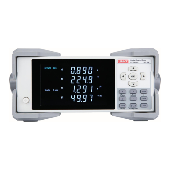
User’s Manual UTE9806+ Smart Digital Power Mete r Chapter 2 Product Introduction 2.1 Product Overview UTE9806+ smart digital power meter is an economic and portable measuring instrument. It is a multi-func- tional measuring instrument which integrating voltage, current, power, active power, apparent power, power factor, voltage peak, current peak, voltage frequency and current frequency. -
Page 8: Technical Index
User’s Manual UTE9806+ Smart Digital Power Mete r 2.2 Technical Index Note:f represent the frequency of input signal in the below table. Model UTE9806+ Remarks Accuracy guarantee VA broken code display, 5 digits,four win- Display range of voltage/cur- dows rent: range of Display Update Rate 0.1S, 0.25S, 0.5S, 1S, 2S, 5S 1%~10%. - Page 9 User’s Manual UTE9806+ Smart Digital Power Mete r Power Resolution 0.001W/0.01W/0.1W/1W Power Factor Range -1.000~1.000 Accuracy of Power Factor ± 0.01 Measuring Range of Fre- Voltage value is higher 40Hz~400Hz quency than range of 10%. Current value is higher Accuracy of Frequency ±0.1% reading than range of 10%.
- Page 10 User’s Manual UTE9806+ Smart Digital Power Mete r Average Function √ RS232(DB9 ; 2-pin: TX, 3-pin: RX, 5-pin: Interface GND) RS485 (DB9 ; 8-pin: A , 9-pin: B ) 1200,2400,4800, 9600, 19.2K,38.4K, 57.6K,115.2K,default 9600. Baud Rate It follows communication protocol of standard SCPI and Modbus.
-
Page 11: Front Panel
User’s Manual UTE9806+ Smart Digital Power Mete r UTE-L16C 16A connection cable with alliga- tor clip x1 UTE-L16A 16A three-pronged plug convert banana head plug connection cable x1 Standard Packing Quantity Standard Packing Size 400mm*300m*325mm Gross Weight of Standard Packing 2.3 Front Panel The front panel and function of UTE9806+, as shown in the following figure. - Page 12 User’s Manual UTE9806+ Smart Digital Power Mete r A Key Switching the measurement parameter of Window A (V/A/W/VA) B Key Switching the measurement parameter of Window B (V/A/W/PF) Switching the measurement parameter of Window C C Key (V/A/W/±Vpk/±Apk) Switching the measurement parameter of Window D (V/A/W/V D Key Hz/A Hz/PF)...
- Page 13 User’s Manual UTE9806+ Smart Digital Power Mete r The display data is RMS. The measured parameter in the current window is RMS volt- age. The measured parameter in the current window is RMS cur- rent. The measured parameter in the current window is active power.
-
Page 14: Chapter 3 Operating Preparation And Measurement
User’s Manual UTE9806+ Smart Digital Power Mete r 2.5 Rear Panel The rear panel and function of UTE9806+, as shown in the following figure and table. Picture of parts Description Under test load/LOAD terminal, it usually used to connect to the in- put port of the product to be test. - Page 15 User’s Manual UTE9806+ Smart Digital Power Mete r 3.1.2 Connecting Test Circuit Please follow the following figure to connect the power and load, and make sure voltage and current is within the measurement range of the instrument. Warning: 1. The load current flows along the thick wire in the above diagram, so these wires should have a large enough safe load capacity.
- Page 16 User’s Manual UTE9806+ Smart Digital Power Mete r Notes: The instrument should be preheated for 30 minutes before entering the stable state. After cutting off the instrument power, it should wait for more than 5 seconds before powering it on again. It is strictly forbid- den to switch the power on and off repeatedly within a short period of time, which will cause the instrument life to shorten and may cause instrument failure.
-
Page 17: Measurement Display
User’s Manual UTE9806+ Smart Digital Power Mete r 3.2 Measurement Display 3.2.1 Window Display UTE9806+ has four display windows, it can display different measurement value at the same time and the parameter of each window can be switch freely, as shown in the following table. (Tick“√”indicates the window can measure the parameter. - Page 18 User’s Manual UTE9806+ Smart Digital Power Mete r 3.2.3 Alarm for Lower Measured Value The alarm will be appear if the measured value of voltage is less than 0.5V or the measured value of cur- rent is less than rated value 0.1%. 1.
-
Page 19: Chapter 4 Measurement
User’s Manual UTE9806+ Smart Digital Power Mete r Chapter 4 Measurement 4.1 Average Filter ·Steps 1. Press【SETUP】key to enter SETUP menu,press【▲】or【▼】key to select submenu“AVG”as shown in the following figure; 2. Press【OK】key to enter the next option, and the press【▲】or【▼】key to switch OFF, ON, DATA; 3. -
Page 20: Measurement Range
User’s Manual UTE9806+ Smart Digital Power Mete r 4.2 Data Update Cycle ·Steps 1. Press【SETUP】key to enter SETUP menu,press【▲】or【▼】key to select submenu“u.rate”as shown in the following figure; 2. Press【OK】key to enter the next option, and the press【▲】or【▼】key to switch 0.1, 0.25, 0.5, 1, 2, 5;... - Page 21 User’s Manual UTE9806+ Smart Digital Power Mete r Voltage range:60V, 600V Current range:0.05A, 0.1A, 10A Step for setting the manual range of voltage 1. Press the secondary auxiliary key【Shift】in the measurement interface, and press【A/V.Range】key to enter the setting interface of voltage range (the first display interface indicates the current range) as shown in the following figure;...
- Page 22 User’s Manual UTE9806+ Smart Digital Power Mete r 4.3.2 Auto Range Follow 4.3.1 section to set the range, select Auto (automatic range) at first. A auto/V auto will display on the left side of the screen when the instrument is in Auto range. If the measurement range is set to auto range, the instrument will synchronous switch range according to the size of input signal.
-
Page 23: Chapter 5 Alarm
User’s Manual UTE9806+ Smart Digital Power Mete r Chapter 5 Alarm 5.1 Turn ON/OFF Alarm Function ·Steps 1. Press【Shift】and【Setup】key to enter Utility menu; 2. Press【▲】or【▼】key to select ALARM, as shown in the following figure; 3. Press【OK】key to enter ALARM menu,press【 ▲】 or【 ▼】 key to select ON or OFF; 4. - Page 24 User’s Manual UTE9806+ Smart Digital Power Mete r 4. Press【OK】key to enter alarm parameter menu, press【▲】or【▼】key to select U, I, P, VA, PF; 5. Press【OK】key to enter the setting menu of parameter, as shown in the following figure; 6. Press 【▲】 or 【▼】 key to select ON or OFF in window B, and press 【OK】 key to save the currently selected and enter Window C;...
- Page 25 User’s Manual UTE9806+ Smart Digital Power Mete r 6. Press【OK】key to save the currently selected and return to previous menu; 7. Press【Hold】key to return to previous menu and back to the measurement interface at last. ·Explanation Alarm function is for detecting whether the measured data is within the set range. UTE9806+ sup- ports alarm of U (voltage), I (current), P (active power), VA (apparent power) and PF (power factor).
- Page 26 User’s Manual UTE9806+ Smart Digital Power Mete r ON: If the measured data is 0, alarm will be activated. OFF: If the measured data is 0, alarm will not be activated. BEEP The number of audible alarms, with a frequency of about three alarms per second. 1~9999: Beep will sound when the alarm is triggered.
-
Page 27: Chapter 6 Communication
User’s Manual UTE9806+ Smart Digital Power Mete r Chapter 6 Communication 6.1 Baud Rate and Modbus Communication Address ·Steps 1. Press【Shift】and【Setup】key to enter Utility menu; 2. Press【▲】or【▼】key to select if and press【OK】key to enter if menu; 3. Press【▲】or【▼】key to select Com, as shown in the following figure; 4. -
Page 28: Communication Command
User’s Manual UTE9806+ Smart Digital Power Mete r 6.2 Communication Command ·Steps 1. Press【Shift】and【Setup】key to enter Utility menu; 2. Press【▲】or【▼】key to select if and press【OK】key to enter if menu; 3. Press【▲】or【▼】key to select type, as shown in the following figure; 4.Press【... -
Page 29: Chapter 7 System Function
User’s Manual UTE9806+ Smart Digital Power Mete r Chapter 7 System Function 7.1 Initialization ·Steps 1. Press【Shift】and【Setup】key to enter Utility menu; 2. Press【▲】or【▼】key to select init; 3. Press【OK】key to enter init submenu, and press【▲】or【▼】key to switch NO or YES, as shown in the following figure;... -
Page 30: Software Information
User’s Manual UTE9806+ Smart Digital Power Mete r Power, Apparent Power, Power Factor 0 Input Alarm Blinking Alarm Delay Times “0010” Beep Beep times“0005” Data Hold Mute Key *Notes: The item cannot be restore to the factory setting: the relevant setting of communication (commu- nication command, baud rate, Modbus communication address) and user’s grade. -
Page 31: Chapter 8 Communication Interface
User’s Manual UTE9806+ Smart Digital Power Mete r Chapter 8 Communication Interface 8.1 RS232 and RS485 Interface UTE9806+ has standard RS232 and RS485 communication interface,PC or PLC can remote control UTE9806+ via SCPI or Modbus command. ·The Definition of Pin UTE9806+ communication interface is DB9 female head, the definition of pin as shown in the following figure. - Page 32 User’s Manual UTE9806+ Smart Digital Power Mete r 8.2.2 PC connect to a single UTE9806+ via RS485 · The number in block diagram represents the pin number of DB9 interface. · Use direct serial port line to connect PC and the RS232 to RS485 convertor. ·...
-
Page 33: Chapter 9 Storage And Calibration
User’s Manual UTE9806+ Smart Digital Power Mete r Chapter 9 Storage and Calibration 9.1 Notice Matters for Storage 9.1.1 The instrument should be stored in the environment which specified in the user manual, refer to Chapter 2.2 storage temperature in Technical Index table. Do not store the instrument in a place with high temperature, high humidity, temperature rapid change or easy condensation. - Page 34 User’s Manual UTE9806+ Smart Digital Power Mete r 9.3 Notice Matters for Calibration Verification and Calibration The precision of standard meter should over a grade than measured meter, standard source should be sta- ble. All the instrument power on 15 minute and wait it to stabilize, and then slowly adjust the output voltage or current of the standard AC source.
-
Page 35: Chapter 10 Optional And Fuse
User’s Manual UTE9806+ Smart Digital Power Mete r Chapter 10 Optional and Fuse 10.1 Optional Testing Wire Uni-trend company provides optional testing wire, there are three model UTE-L16A, UTE-L10A, UTE-L16C, as shown in the following figure. User can purchase one or multiple testing wires according your own needs. The following table is match solution for user to reference. - Page 36 User’s Manual UTE9806+ Smart Digital Power Mete r Connect scheme of testing wire as shown in the following figure. Warning:Before connect with circuit, please make sure the power is cut off to prevent from electric shock. 10.2 Specification of Fuse This instrument has 1 spare fuse stored in the fuse box.
-
Page 37: Appendix 1 Symbol And Formula Of Measurement
User’s Manual UTE9806+ Smart Digital Power Mete r Appendix 1 Symbol and Formula of Measurement Normal Measurement Measurement Function [Unit] Operation Formula Explanation Voltage U [V] u(n) represents instantaneous value of voltage; Current I [A] ...
Need help?
Do you have a question about the UTE9806+ and is the answer not in the manual?
Questions and answers