Table of Contents
Advertisement
Quick Links
© Copyright 1996, 1997
EVERTZ MICROSYSTEMS LTD.
5288 John Lucas Drive, Burlington, Ontario, Canada, L7L 5Z9
Phone:
905-335-3700
Fax:
905-335-3573
Internet: Tech Support:
Sales:
Web Page:
Revision 1.1. March 1997
The material contained in this manual consists of information that is the property of Evertz Microsystems and is
intended solely for the use of purchasers of the model 5010-SIE Source ID Encoder. Evertz Microsystems
expressly prohibits the use of this manual for any purpose other than the operation of the 5010-SIE.
All rights reserved. No part of this publication may be reproduced without the express written permission of
Evertz Microsystems Ltd. Copies of this guide can be ordered from your Evertz products dealer or from Evertz
Microsystems.
Models 5010 SIE
Source ID Encoder
Instruction Manual
eng@evertz.com
sales@evertz.com
http://www.evertz.com
Advertisement
Chapters
Table of Contents

Related Manuals for evertz 5010 SIE


Summary of Contents for evertz 5010 SIE
- Page 1 Revision 1.1. March 1997 The material contained in this manual consists of information that is the property of Evertz Microsystems and is intended solely for the use of purchasers of the model 5010-SIE Source ID Encoder. Evertz Microsystems expressly prohibits the use of this manual for any purpose other than the operation of the 5010-SIE.
- Page 2 WARNING Changes or Modifications not expressly approved by Evertz Microsystems Ltd. could void the user’s authority to operate the equipment. Use of unshielded plugs or cables may cause radiation interference. Properly shielded interface...
- Page 3 Model 5010-SIE Source ID Encoder Manual REVISION HISTORY REVISION DESCRIPTION DATE Original issue Feb 96 1.01 Manual Change Sheet 1.0-1 inserted Apr 96 Incorporated change sht 1.0-1 Mar 97 Updated section on Model 7225 1.1.1. Manual Change Sheet 1.0-2 inserted Feb.
- Page 4 Model 5010-SIE Source ID Encoder Manual 5010-SIE Manual Change Sheet 1.0-1 The following document describes the hardware changes to the 5010-SIE related to adding a bypass relay on the VITC generator output. References to the 5010-SIE manual are to version 1.0 printed Feb. 1996.
- Page 5 Model 5010-SIE Source ID Encoder Manual Manual Change Sheet 1.0-2 The following document describes the changes to the 5010-SIE that allow it to interface to Profile Disk Recorders with the LVS software. The section numbers of the 5010-SIE manual (version 1.0 printed Feb.
- Page 6 Model 5010-SIE Source ID Encoder Manual Manual Change Sheet 1.0-2 SERIAL: A 9 pin female 'D' connector for connection to the RS-232 connector on the D3 video recorder, the 7225 time code/status converter used with the analog tape machines or the serial port on a Profile Disk recorder.
- Page 7 Model 5010-SIE Source ID Encoder Manual Manual Change Sheet 1.0-2 window on or off. Press the WINDOW key again to select the SRC ID VCG window. Press the WINDOW key again to select the next window and so on. The 5010-SIE returns to the normal VCG display mode after the last window has been selected.
- Page 8 Model 5010-SIE Source ID Encoder Manual Manual Change Sheet 1.0-2 GEN SRC ID MODE VCG CHAR SIZE VIDEO TYPE 5 id Size tiny Vtype fixed ntsc 9 id Size small HORZ CHAR SIZE 5 id+sts Size large Horz size 02 Mod tim 5 id VCG CHAR STYLE DISPLAY LEVEL...
- Page 9 Model 5010-SIE Source ID Encoder Manual Manual Change Sheet 1.0-2 3.8.1 ON AIR Character Keyer mode Select ON AIR MODE ON to blank all the Charater windows when the VTR Status is Play or VAR, or when the ON AIR remote control input is closed to ground. When ON AIR MODE OFF is selected, the Charater windows ignore the VTR Status and the ON AIR remote control input.
- Page 10 Model 5010-SIE Source ID Encoder Manual Manual Change Sheet 1.0-3 The following document describes the changes to the manual relating to the special 5010-SIE-NBC version. The section numbers of the 5010-SIE manual (version 1.1 printed March 1997) are shown in bold.
- Page 11 Lance HSE-100 Edit Controller and a Sony VTR. The use of other edit controllers may not give expected results on the VTR status of the 5010-SIE-NBC. The wiring diagram below can be used to make an appropriate cable. SID Encoder Evertz 5010-SIE Edit Controller Lance HSE-100 Sony DVW-A500P...
- Page 12 Model 5010-SIE Source ID Encoder Manual Manual Change Sheet 1.0-3 PARALLEL REMOTE CONTROL FUNCTIONS A 9 pin female 'D' connector used for parallel remote control inputs. Loop through outputs have been provided on two of the inputs for ease of wiring multiple units in parallel. These loop through outputs are driven in the software so that they follow the sense of the respective inputs.
-
Page 13: Table Of Contents
Model 5010-SIE Source ID Encoder Manual TABLE OF CONTENTS INTRODUCTION ......................... 1-1 1.1. HOW TO USE THIS MANUAL ....................1-1 1.2. DEFINITIONS ..........................1-1 INSTALLATION........................... 2-1 2.1. REAR PANEL CONNECTIONS ....................2-1 2.1.1. Vertical Interval Timecode Video Connections ............. 2-1 2.1.2. - Page 14 Model 5010-SIE Source ID Encoder Manual 3.4. PROGRAMMING THE GENERATOR SETUP FUNCTIONS ............3-7 3.4.1. Configuring the Generator Operating Modes ..............3-7 3.4.2. Turning the VITC Generator On ..................3-8 3.4.3. Selecting the Lines to Generate VITC On..............3-8 3.4.4. Selecting the Generator Drop Frame Mode ..............
- Page 15 Model 5010-SIE Source ID Encoder Manual Figures Figure 2-1: Rear Panel Layout....................2-1 Figure 2-2: 7225 Rear Panel Connections.................. 2-6 Figure 2-3: 5010-SIE to 7225 Time Code / Status Converter Cable........... 2-7 Figure 2-4: 7225 To BVU 800 Parallel Tally Cable Wiring List ........... 2-8 Figure 2-5: 7225 TO BVW 75 Parallel Tally Cable Wiring List............
- Page 16 Model 5010-SIE Source ID Encoder Manual Component Layout Top Side ................5223-80A Component Layout Bottom Side ................5223-81A 5010 Parts Lists ......................Parts List # 5200 Main Board .....................BAM5200TP 5220 Display Board..................BAM5220DS 5235 VITC Generator Submodule 5010............BAS5235VG 8103 Power Supply..................BAM8103PS Misc.
-
Page 17: Introduction
Model 5010 Time Code Generator / Reader Manual INTRODUCTION The Model 5010-SIE Source ID Encoder provides a cost effective method of keying timecode, source ID and machine status information into the analog video. Features: • Character Inserter displays timecode, source ID and VTR status in the picture •... - Page 18 Model 5010 Time Code Generator / Reader Manual DROP FRAME: In NTSC systems, where the frame rate is 29.97002618 frames per second, the drop frame mode permits time of day indexing of the frame numbers by dropping certain frame numbers. Specifically, frames 0, and 1 at the beginning of each minute except minutes 0, 10, 20, 30, 40 &...
-
Page 19: Installation
Model 5010-SIE Source ID Encoder Manual INSTALLATION 2.1. REAR PANEL CONNECTIONS EVERTZ model 5010 SIE MADE IN CANADA VITC GEN MICROSYSTEMS LTD FUSE PARALLEL 115 V: INPUT .25 A SERIAL 115Vac 230 V: .125 A INPUT REF VIDEO IN 75 OHM... -
Page 20: Gen Lock Connections
Model 5010-SIE Source ID Encoder Manual VIDEO CHAR GEN OUTPUT: A BNC connector which outputs the VIDEO CHAR GEN INPUT video with characters inserted. This output is also used to display the on screen programming menu and is normally connected to a video monitor. -
Page 21: Mounting
Model 5010-SIE Source ID Encoder Manual 2.2. MOUNTING The model 5010-SIE is equipped with rack mounting angles and fits into a standard 19 inch by 1 3/4 inch (483 mm x 45 mm) rack space. mounting angles may be removed if rack mounting is not desired. 2.3. -
Page 22: Video Connections
Model 5010-SIE Source ID Encoder Manual Never replace with a fuse of greater value. Make sure that the arrow is pointing down when you replace the fuse holder. Close the door on the power entry module and connect the mains voltage. -
Page 23: Connecting The 5010-Sie To The Vtr Remote Control Port
Model 5010-SIE Source ID Encoder Manual 2.5. CONNECTING THE 5010-SIE TO THE VTR REMOTE CONTROL PORT The 5010-SIE serial remote control port is designed to communicate with the RS-232 port on a Panasonic AJ-D350 VTR. This remote port is used to obtain timecode and status information from the VTR. -
Page 24: Connecting The 5010-Sie To The 7225 Converter
Model 5010-SIE Source ID Encoder Manual SERIAL I/O: A 9 pin female 'D' connector for connection to the 5010-SIE Source ID Encoders Description not used not used do not connect not used RS-232 Receive Signal Ground not used RS 232 Transmit not used TRANSPORT STATUS: A 15 pin female high density 'D' connector for... -
Page 25: Connecting The Vtr Parallel Remote Control Port To The 7225 Converter
Model 5010-SIE Source ID Encoder Manual RS-232 Transmit -------------------------------------------------------- RS-232 Receive Ground -------------------------------------------------------- Signal Ground RS-232 Receive -------------------------------------------------------- RS-232 Transmit Figure 2-3: 5010-SIE to 7225 Time Code / Status Converter Cable 2.6.3. Connecting the VTR Parallel Remote Control Port to the 7225 Converter Figure 2-4 to Figure 2-7 are cable diagrams for connecting the 7225 to various VTR’s. -
Page 26: Figure 2-4: 7225 To Bvu 800 Parallel Tally Cable Wiring List
Model 5010-SIE Source ID Encoder Manual 7225 END BVU 800 END 15 PIN MALE HIGH DENSITY “D” 36 PIN TRW #77-30360 AMP #748364-1 OR EQUIVALENT DESCRIPTION DESCRIPTION Machine Select 1 ------------------------------------------------- 35 Ground Machine Select 2 ------------------------------------------------- 35 Ground Machine Select 3 ------------------------------------------------- 35 Ground Stop... -
Page 27: Figure 2-5: 7225 To Bvw 75 Parallel Tally Cable Wiring List
Model 5010-SIE Source ID Encoder Manual 7225 END BVW 75 END 15 PIN MALE HIGH DENSITY “D” 36 PIN TRW #77-30360 AMP #748364-1 OR EQUIVALENT DESCRIPTION DESCRIPTION Machine Select 1 ------------------------------------------------- Machine Select 2 ------------------------------------------------- 35 Ground Machine Select 3 ------------------------------------------------- 35 Ground Stop... -
Page 28: Figure 2-6: 7225 To Bvh 2000 Parallel Tally Cable Wiring List
Model 5010-SIE Source ID Encoder Manual 7225 END BVH 2000 END 15 PIN MALE HIGH DENSITY “D” 50 PIN MALE “D” TYPE AMP #748364-1 OR EQUIVALENT DESCRIPTION DESCRIPTION Machine Select 1 ------------------------------------------------- 33 Ground Machine Select 2 ------------------------------------------------- Machine Select 3 ------------------------------------------------- 33 Ground Stop... -
Page 29: Figure 2-7: 7225 To Au 660 Parallel Tally Cable Wiring List
Model 5010-SIE Source ID Encoder Manual 7225 END AU 600 END 15 PIN MALE HIGH DENSITY “D” 50 PIN MALE “D” TYPE AMP #748364-1 OR EQUIVALENT DESCRIPTION DESCRIPTION Machine Select 1 ------------------------------------------------- Machine Select 2 ------------------------------------------------- Machine Select 3 ------------------------------------------------- 47 Ground Stop ------------------------------------------------- 31... - Page 30 Model 5010-SIE Source ID Encoder Manual This page left intentionally blank INSTALLATION Page 2-12...
-
Page 31: Operating Instructions
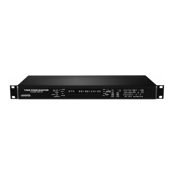
5010-SIE STATUS SHIFT WINDOW SELECT SET-UP CHAR COMM evertz VIDEO DISPLAY ON/OFF CHAR Figure 3-1: Front Panel Layout The display area consists of an 16 digit alphanumeric display, 6 LED status indicators and an 10 pushbutton keypad. The keypad is used to program the source ID message that will be encoded, to control the front panel menu system, to position the character display windows, and to provide control of the front panel display. -
Page 32: The Setup Pushbutton Group
Model 5010-SIE Source ID Encoder Manual 3.1.1. The Setup Pushbutton Group VITC CHAR WINDOW SELECT SET-UP CHAR ON/OFF CHAR The Setup key group consists of the SELECT, SETUP and !, ", #, $ keys and is used to navigate the front panel programming menu system, to position character windows and to enter the source ID message. -
Page 33: The Character Window Pushbutton Group
Model 5010-SIE Source ID Encoder Manual 3.1.2. The Character Window Pushbutton Group CHAR GEN WINDOW Initiates VCG window select mode and highlights the Time VCG window. Use the arrow keys to move the window, use the CHAR GEN ON/OFF key to turn the window on or off. -
Page 34: Front Panel Display Functions
Model 5010-SIE Source ID Encoder Manual 3.2. FRONT PANEL DISPLAY FUNCTIONS The DISPLAY key is used to select which data is being displayed in the alphanumeric display. Each time the DISPLAY key is pressed, the front panel display cycles to the next available display. Currently there are three types of display data: SRC ID: VTR-10... -
Page 35: Figure 3-2: On Screen Programming Menu Overview
Model 5010-SIE Source ID Encoder Manual GENERATOR CONFIG SRC ID MODE CHAR SIZE VIDEO TYPE 5 SRC ID TINY VIDEO TYPE FIXED TO 9 SRC ID SMALL NTSC 5 SRC ID+STS LARGE HORZ CHAR SIZE TIME 5 SRC ID CHAR STYLE HORIZONTAL TIME 9 SRC ID... - Page 36 Model 5010-SIE Source ID Encoder Manual To enter the on screen programming menus, press the SETUP key. The character generator will show the last format screen that was used with the currently selected item highlighted. The two horizontal arrow keys (!, ") allow you to move horizontally to another drop down menu when the sub menu is hidden.
-
Page 37: Programming The Generator Setup Functions
Model 5010-SIE Source ID Encoder Manual 3.4. PROGRAMMING THE GENERATOR SETUP FUNCTIONS The GENERATOR drop down menu is used to program various generator modes such as selecting source ID encoding modes, VITC keyer enable, VITC generator line numbers, etc. Figure 3-4 shows the items on the GENERATOR drop down menu. -
Page 38: Turning The Vitc Generator On
Model 5010-SIE Source ID Encoder Manual 5 SRC ID + STS Turns off the time, turns on the status and encodes the 5 character ID format. TIME 5 SRC ID Turns on the time, turns off the status and encodes the 5 character ID format. -
Page 39: Configuring Whether The 5010-Sie Will Use Ltc Or Vitc From The Vtr
Model 5010-SIE Source ID Encoder Manual time information, the generator drop frame mode follows the source of the time information (usually VTR time) 3.4.5. Configuring Whether the 5010-SIE Will Use LTC or VITC from the VTR The VITC RDR MODE menu item on the GENERATOR menu controls whether the 5010-SIE will use LTC or VITC from the VTR when it is encoding time information. - Page 40 Model 5010-SIE Source ID Encoder Manual The VCG drop down menu is used to select various characteristics of the VCG display. Figure 3-5 shows the items on the VCG drop down menu. CHAR SIZE The following descriptions appear in the order they appear on the menu. TINY SMALL LARGE...
-
Page 41: Programming The Overall Configuration Functions
Model 5010-SIE Source ID Encoder Manual The VCG SYMBOLS menu item is used to select whether & symbol will VCG SYMBOLS be shown in front of the source ID displays of the VCG. DISPLAY BLANK Select DISPLAY to display the VCG symbols. Select BLANK to blank the VCG symbols. -
Page 42: Selecting The Video Standard
Model 5010-SIE Source ID Encoder Manual 3.6.1. Selecting the Video Standard The VIDEO TYPE menu item is used to select the video standard of the VIDEO TYPE program video. For the 5010-SIE the video type is fixed to NTSC VIDEO TYPE FIXED TO NTSC 3.6.2. -
Page 43: Character Source Id Format
Model 5010-SIE Source ID Encoder Manual of the Source ID number are also blanked and the numbers are left justified (moved adjacent to the dash ‘-’). 3.7.2. 9 Character Source ID Format The second format consists of up to 9 alphanumeric characters, and are shown in the following format: AAAAAAAAA The A represents alpha-numeric message characters. -
Page 44: Character Generator Functions
Model 5010-SIE Source ID Encoder Manual exit the Source ID programming mode without changing the programmed message press the SETUP key. 3.8. CHARACTER GENERATOR FUNCTIONS Two separately positionable character windows displaying Time or Source ID/Status (user bits) are available. Although the Source ID and Status windows move together, they can be independently turned on and off. -
Page 45: Character Generator On/ Off Controls
Model 5010-SIE Source ID Encoder Manual 3.8.3. Character Generator On/ Off Controls There are several factors that control whether the character generator will be turned on or off. In order of priority these are: When the VTR is in Play the characters will always be turned off. The CHAR LED will blink if the characters were turned off by the PLAY mode of the VTR. -
Page 46: Parallel Remote Control Functions
Model 5010-SIE Source ID Encoder Manual 3.9. PARALLEL REMOTE CONTROL FUNCTIONS A 9 pin D connector located on the rear panel labelled REMOTE CTL provides 6 parallel control inputs for remote control of some of the model 5010-SIE functions. The pinout of the D connector is as follows: Description Frame Ground not used... - Page 47 Model 5010-SIE Source ID Encoder Manual This page left intentionally blank OPERATING INSTRUCTIONS Page 3-17...
- Page 48 Model 5010-SIE Source ID Encoder Manual This page left intentionally blank OPERATING INSTRUCTIONS Page 3-18...
-
Page 49: Technical Description
Model 5010-SIE Source ID Encoder Manual TECHNICAL DESCRIPTION 4.1. OVERVIEW The model 5010-SIE Source ID Encoder combines the latest LSI technology with sophisticated microcontroller firmware to provide a powerful, flexible system. A 16 digit alphanumeric display can be quickly delegated to show the required data. The character inserter provides an on screen programming menu system, which is used to configure the various operating modes. -
Page 50: Figure 4-2: Main Board Jumper Locations
Model 5010-SIE Source ID Encoder Manual Figure 4-2: Main Board Jumper Locations TECHNICAL DESCRIPTION Page 4-2... -
Page 51: Jumper Functions - Main Board
Model 5010-SIE Source ID Encoder Manual 4.2.2. Jumper Functions - Main Board All jumpers except JP9 are printed circuit board links and are installed in the default position. To change the position, the board link must be cut and a wire link must be installed in the desired location. Parallel I/O 1 (pin 9) Installed When link is installed, Output 1 has 4.7K pull-... -
Page 52: Jumper Functions - Vitc Generator Submodule
Model 5010-SIE Source ID Encoder Manual JP21 UART TX Not installed for 5010-SIE JP22 MCU RX Not installed for 5010-SIE JP23 MCU TX Not installed for 5010-SIE JP24 VCG Video In VITC Reader Video connected to RDR IN Loop. VCG video connected to Gen Video In loop. -
Page 53: Circuit Description
Model 5010-SIE Source ID Encoder Manual Fill Install for Analog Video Out Install for Digital Video Out Install for Analog Video Out Install for Digital Video Out Video Out Sel Selects Terminated Video In and assigns Out A and B as outputs Selects high impedance video in loop and Out B as an output. -
Page 54: Front Panel Display And Pushbuttons (5220-31)
Model 5010-SIE Source ID Encoder Manual 15.36 MHz frequency is internally divided by 12, resulting in a processor operating frequency of 1.28 MHz. CHARACTER GEN REF VIDEO REMOTE VITC GENERATOR CONTROL SERIAL & REF VIDEO CHAR GEN VITC GEN PARALLEL SYNC KEYER KEYER... -
Page 55: Vitc Generator (5235-31 To 5235-33)
Model 5010-SIE Source ID Encoder Manual The status LED's are controlled by interface driver U3. This driver is accessed with a serial clock and data stream once per frame. When all the LED information has been shifted into the driver, it is latched there by the LEDSTB signal from the MCU (display header pin 10). -
Page 56: Character Generator Sync Separator And Keyer (5200-36)
Model 5010-SIE Source ID Encoder Manual The starting position of the VITC on the line is fixed internally in the LCA such that the first bit of code is 10.5 µsec (11.5 µsec for PAL) after the leading edge of horizontal sync. Once per field, the MCU loads the VITC bit pattern for a particular line into static RAM U10. -
Page 57: Character Generator Logic (5200-35)
Model 5010-SIE Source ID Encoder Manual To calibrate the video keyer, connect colour bars from your sync generator to the Reader Video input loop of the model 5010 and to channel A of your oscilloscope and terminate it. Connect one of the video outputs of the model 5010 to channel B of your scope and terminate it. -
Page 58: Reference Video (5200-37)
Model 5010-SIE Source ID Encoder Manual 4.3.6. Reference Video (5200-37) The Reference Gen-lock video is buffered by Q8 and Q6 and distributed to the reference video sync separator. The sync separator U54 (EL4581) slices the input video at 50% of the sync tip level to provide precision timing for the colour frame circuitry. - Page 59 Model 5010-SIE Source ID Encoder Manual panel will display LOAD FLASH - 38400. The default baud rate for reprogramming is 38400. To set up the 5010-SIE for programming at 9600 baud hold down the $ key while you apply power to the 5010-SIE. When the 5010-SIE completes its boot-up sequence, the front panel will display LOAD FLASH - 9600 The 5010-SIE firmware is contained in an Intel HEX format file...
- Page 60 Model 5010-SIE Source ID Encoder Manual x key.) Repeat steps 3 to 6 to try to correct the problem. If you still have trouble, try programming at 9600 baud. The reprogramming will be complete when the Flash Loader announces "Hex file transmitted successfully" and returns you to the DOS prompt.
- Page 61 Phone: 905-335-3700 Fax: 905-335-3573 BBS: 905-335-9131 Internet: Tech support: eng@evertz.com Sales info: sales@evertz.com INSTRUCTIONS FOR UPGRADING 5010-SIE WITH BYPASS RELAY MODIFICATION These devices are subject to damage by electrostatic charge buildup which can occur with improper handling. The devices should always be carried and stored in the anti-static carrier tube provided.
Need help?
Do you have a question about the 5010 SIE and is the answer not in the manual?
Questions and answers