Table of Contents
Advertisement
Quick Links
8x 3G SDI Inputs, 4x 10GbE SFP Cages
© Copyright 2018
EVERTZ MICROSYSTEMS LTD.
5292 John Lucas Drive
Burlington, Ontario
Canada L7L 5Z9
Phone:
+1 905-335-3700
Sales:
sales@evertz.com
Tech Support: service@evertz.com
Web Page:
http://www.evertz.com
December
Version 1.0,
The material contained in this manual consists of information that is the property of Evertz Microsystems and is intended solely for the use of
purchasers of the 570REM-RX8-10GE. Evertz Microsystems expressly prohibits the use of this manual for any purpose other than the operation of
the 570REM-RX8-10GE.
All rights reserved. No part of this publication may be reproduced without the express written permission of Evertz Microsystems Ltd. Copies of
this manual can be ordered from your Evertz dealer or from Evertz Microsystems.
570REM-RX8-10GE
8x J2K Decoders Driving 2x UHD or
Fax: +1 905-335-3573
Fax: +1 905-335-7571
Twitter:
2018
User Manual
@EvertzTV
Advertisement
Table of Contents

Subscribe to Our Youtube Channel
Related Manuals for evertz 570REM-RX8-10GE


Summary of Contents for evertz 570REM-RX8-10GE
- Page 1 2018 The material contained in this manual consists of information that is the property of Evertz Microsystems and is intended solely for the use of purchasers of the 570REM-RX8-10GE. Evertz Microsystems expressly prohibits the use of this manual for any purpose other than the operation of the 570REM-RX8-10GE.
- Page 2 This page left intentionally blank...
- Page 3 IMPORTANT SAFETY INSTRUCTIONS The lightning flash with arrowhead symbol within an equilateral triangle is intended to alert the user to the presence of uninsulated “Dangerous voltage” within the product’s enclosure that may be of sufficient magnitude to constitute a risk of electric shock to persons. The exclamation point within an equilateral triangle is intended to alert the user to the presence of important operating and maintenance (Servicing) instructions in the literature accompanying the product.
- Page 4 WARNING Changes or modifications not expressly approved by Evertz Microsystems Ltd. could void the user’s authority to operate the equipment. Use of unshielded plugs or cables may cause radiation interference. Properly shielded interface cables...
- Page 5 Evertz products are for informational use only and are not warranties of future performance, either expressed or implied. The only warranty offered by Evertz in relation to this product is the Evertz standard limited warranty, stated in the sales contract or order confirmation form.
- Page 6 570REM-RX8-10GE User Manual This page left intentionally blank Revision 1.0...
-
Page 7: Table Of Contents
570REM-RX8-10GE User manual TABLE OF CONTENTS OVERVIEW ........................... 1 GETTIMG STARTED ........................3 2.1. REAR AND FRONT PLATE ....................3 2.2. CARE AND HANDELING OF OPTICAL FIBER ..............4 2.3. HARDWARE INSTALLATION ..................... 4 SPECIFICATIONS ........................5 3.1. SERIAL DIGITAL VIDEO ..................... 5 3.2. - Page 8 570REM-RX8-10GE User manual 4.5. IP INPUT CONTROL ......................17 4.5.1. MPPM Control ......................17 4.5.2. Input SFP Port Selection ..................18 4.5.3. Input Port Control ....................18 4.5.4. ARP Control ......................18 4.6. BREAKWAY AUDIO INPUT CONTROL ................19 4.6.1. Breakaway Audio Control ..................19 4.7.
- Page 9 570REM-RX8-10GE User manual FIGURES Figure 1-1 : 570REM-RX8-10GE Block Diagram ................1 Figure 2-1 : 570REM Rear Plate ....................3 Figure 4-1 : WebEASY - Login Menu ................... 7 ® Figure 4-2 : WebEASY - 570REM-RX8-10GE Main Menu............8 ®...
- Page 10 570REM-RX8-10GE User manual This page left intentionally blank Page iv Revision 1.0...
-
Page 11: Overview
The 570REM-RX8-10GE is a high performance multi-channel JPEG2000 decoding platform. The exceptional density of the 570REM-RX8-10GE enables up to 8x channels of 3G, HD/SDI, SD/SDI or up to 2x channels of UHD JPEG2000 decoding. The 570REM-RX8-10GE provides 2x SDI outputs for every JPEG2000 decode. - Page 12 570REM-RX8-10GE User manual This page left intentionally blank Page 2 Revision 1.0...
-
Page 13: Gettimg Started
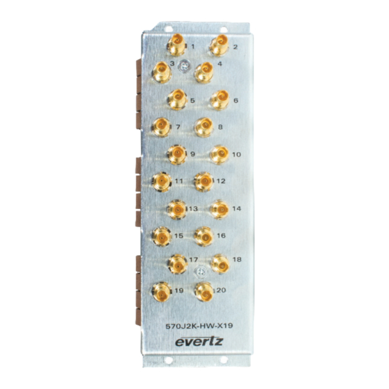
REAR AND FRONT PLATE The rear plate of 570REM-RX8-10GE is equipped with 20 Mini-Din connectors. Figure 2-1 : 570REM Rear Plate The front plate of 570REM-RX8-10GE has 12 available SFP slots. These SFP slots can be populated with SFP10G-TR13-A. Page 3... -
Page 14: Care And Handeling Of Optical Fiber
Evertz recommends that the user maintains a minimum bending radius of 5 cm to avoid fiber-bending loss that will decrease the maximum attainable distance of the fiber cable. The Evertz fiber optic modules come with cable lockout devices, to prevent the user from damaging the fiber by installing a module into a slot in the frame that does not have a suitable I/O module. -
Page 15: Specifications
570REM-RX8-10GE User manual SPECIFICATIONS 3.1. SERIAL DIGITAL VIDEO Standards: • SMPTE 424M (3Gb/s) • SMPTE 292M (1.5Gb/s) • SMPTE 259M (270Mb/s) 3.2. SERIAL VIEDO INPUTS Number of Inputs Not Applicable Input Equalization Return Loss 3.3. SERIAL VIDEO OUTPUT Number of Outputs... -
Page 16: Enclosures
User manual 3.8. ENCLOSURES 570FR 3RU Chassis S570FR 1RU Chassis Ordering Information 570REM-RX8-10GE: 8x J2K Decoders driving 2x UHD or 8x 3G/HD/SD SDI output, 4x 10GbE SFP Cages (SFP+ sold separately) SFP Modules: • SFP10G-TR13-A 10GbE Optical SFP+ • SFP10G-TR85-A... -
Page 17: Web Interface
570REM-RX8-10GE User manual WEB INTERFACE The 570REM-RX8-10GE series of products are controlled using Web Interface. WebEasy operates using Ethernet and SNMP control protocols. Login After the card has been installed and configured with the required network addresses, it can be completely configured using the web interface. -
Page 18: Figure 4-2 : Webeasy - 570Rem-Rx8-10Ge Main Menu
570REM-RX8-10GE User manual Figure 4-2 : WebEASY - 570REM-RX8-10GE Main Menu ® Page 8 Revision 1.0... -
Page 19: System
570REM-RX8-10GE User manual 4.1. SYSTEM Figure 4-3 : WebEASY - System (Part 1) ® Card Alias: This parameter indicates the card alias string. 4.1.1. Control Port Configuration IP Address: This parameter allows the user to set IP address for control port. -
Page 20: Data Port Monitor
570REM-RX8-10GE User manual Mac Address: This parameter reflects the Mac address for Data Port. 4.1.3. Data Port Monitor Port Link Status: This parameter indicates the link status for Data port. Received Data Ethernet Total Bitrate: This parameter indicates bitrate which is received on this Ethernet port, unit is kbps. -
Page 21: Sfp Monitor
570REM-RX8-10GE User manual Figure 4-4 : WebEASY - System (Part 2) ® 4.1.4. SFP Monitor SFP Part Number: This parameter indicates the part number of SFP. SFP Type: This field indicates the type of SFP. SFP Rx Power Level: This field indicates the received power level of SFP. -
Page 22: Time Management
570REM-RX8-10GE User manual 4.1.7. Time Management Time Source: This dropdown allows the user to select the system time source which can be NTP or Local time. If NTP: Timezone Offset: This control allows the user to define timezone offset. Day Light Savings: This dropdown allows the user to select whether to apply Day Light savings or not. -
Page 23: Product Features
570REM-RX8-10GE User manual 4.2. PRODUCT FEATURES Figure 4-5 : WebEASY - Product Features ® 4.2.1. License Control Product Serial Number: This parameter displays the card serial number same as the card MIB control. This is needed for the webpage. Product Mac Address: This parameter displays the card MAC address. -
Page 24: Din Output Control
570REM-RX8-10GE User manual 4.3. DIN OUTPUT CONTROL Figure 4-6 : WebEASY - DIN Output Control ® 4.3.1. Output Control Loss Of Video: This dropdown allows the user to select the output video color that will be sent on output when input ASI is missing and the output video mode is set to continoues. -
Page 25: Frame Sync Status
570REM-RX8-10GE User manual 4.3.4. Frame Sync Status Frame Delay: This field displays the frame delay for this channel. Sub-Frame Delay: This field displays the sub frame delay time for this channel. TS Total Delay: This field displays the frame delay time for this channel. -
Page 26: Ip Output Control
570REM-RX8-10GE User manual Encapsulation Rate Limit: This dropdown allows the user to set the bandwidth limit for SMPTE 2110 or 2022-6 IP output. 4.4.2. IP Output Control For SFPP 1 to 6: IP Output Enable: This is for enable/disable output. -
Page 27: Ip Input Control
570REM-RX8-10GE User manual 4.5. IP INPUT CONTROL Figure 4-8 : WebEASY - IP Input Control ® 4.5.1. MPPM Control MPPM Mode: This parameter allows the user to set the MPPM mode. Possible options are WAN and LAN. WAN is used for wide area networks where link jitter and skew between networks needs to be compensated. -
Page 28: Input Sfp Port Selection
570REM-RX8-10GE User manual Playout Delay: This parameter allows the user to see the playload delay. Playout delay should double the network skew. Smoother: This parameter allows the user to enable the MPPM smoother for jitter tolerance. Skew: This parameter indicates the delay difference between the main and backup streams. -
Page 29: Breakway Audio Input Control
570REM-RX8-10GE User manual 4.6. BREAKWAY AUDIO INPUT CONTROL Figure 4-9 : WebEASY - Breakaway Audio Input Control ® 4.6.1. Breakaway Audio Control Breakaway Audio Enable: This field allows the user to enable/disable the breakaway audio decoding. 10G Link Select: This control allows the user to select auto merge, main or backup for breakaway audio decoding. -
Page 30: Decoder Control
570REM-RX8-10GE User manual 4.7. DECODER CONTROL Figure 4-10 : WebEASY - Decoder Control ® For Internal Decoder Core 1-8: Page 20 Revision 1.0... -
Page 31: Rx Input Monitor
Signal, 9- DMAC, 10- FM Radio, 11-NTSC, 12- Data Broadcast, N/A- means that a valid service type was not found or there is no private descriptor. PSD Provider Name: This parameter indicates the provider name read from the Evertz private service descriptor (79) from the PMT. -
Page 32: Jitter Tolerance
4.7.4. Jitter Tolerance Consult Evertz Service before configuring this control. When the network jitter is in access of 30ms, Jitter tolerance adds further resilience to the input detection. 4.7.5. Codec Latency This is reserved for future use. -
Page 33: Rtp And Master Pcr Control
570REM-RX8-10GE User manual 4.8. RTP AND MASTER PCR CONTROL Figure 4-11 : WebEASY - RTP and Master PCR Control ® 4.8.1. PTP and Master PCR Control PTP or Master PCR Selection: This parameter allows the user to select the decoder master PCR reference as either PTP or PCR. -
Page 34: Master Pcr Control
570REM-RX8-10GE User manual 4.8.3. Master PCR Control IP Address: This field allows the user to set the IP address from which to obtain the Master PCR time reference. UDP Port Number: This field allows the user to set the UDP port number from which to obtain the Master PCR time reference. -
Page 35: Ip Input Monitor
570REM-RX8-10GE User manual 4.9. IP INPUT MONITOR Figure 4-12 : WebEASY - IP Input Monitor ® 4.9.1. Input Stream Received Total TS Bitrate: This field indicates the total bitrate for the multicast stream specified. Received Null Packet Bitrate: This parameter shows total NULL packet bitrate for multicast stream specified. -
Page 36: Input Ip Packet Monitor
570REM-RX8-10GE User manual 4.9.2. Input IP Packet Monitor For SFP1G-10G Main & Backup IP Packet Drop Count: This parameter shows the IP packet drop event count. IP Packet Bit Rate: This parameter shows the IP packet bit rate. 4.9.3. IP Packet Drop Counter Clear Clear: This control allows the user to clear the IP packet drop count. -
Page 37: Internal Decoder Core
570REM-RX8-10GE User manual 4.10.1. Internal Decoder Core For Decoder (1-8): Program Num In TS: This parameter highlights the program number for the encoded transport stream. PMT PID: This parameter highlights the PMT PID. PCR PID: This parameter highlights the PCR PID. -
Page 38: System Notify
570REM-RX8-10GE User manual 4.11. SYSTEM NOTIFY Figure 4-14 : WebEASY - System Notify ® 4.11.1. System Monitoring Control Temperature Warning Threshold: This parameter allows the user to set the threshold for the temperature overheat. Received Bandwidth Threshold: This parameter allows the user to set the received bandwidth threshold. -
Page 39: Decoder Notify
570REM-RX8-10GE User manual 4.12. DECODER NOTIFY Figure 4-15 : WebEASY - Decoder Notify ® 4.12.1. Decoder Notification Decoder Input Traps: This parameter is used to turn input traps On and Off. Decoder Input Faults: This control checks whether an input fault is currently present or not. - Page 40 570REM-RX8-10GE User manual This page left intentionally blank Page 30 Revision 1.0...
-
Page 41: Firmware Upgrade
570REM-RX8-10GE User manual FIRMWARE UPGRADE Using WebEASY on a web interface is the recommended way to load the firmware onto the 570REM ® modules. On the top of the web page for the 570REM modules, there is a button labeled Upgrade. The Upgrade tab is used to check current firmware version and upload the latest firmware (Figure 5-1). -
Page 42: Figure 5-3 : Webeasy - Firmware Upgrade Menu\Selecting Firmware File
570REM-RX8-10GE User manual Figure 5-3 : WebEASY - Firmware Upgrade Menu\Selecting Firmware File ® Once selected, click open to advance to next step. Click upgrade and watch progress bar for status. Once completed, the device will automatically restart. Page 32...
Need help?
Do you have a question about the 570REM-RX8-10GE and is the answer not in the manual?
Questions and answers