Table of Contents
Advertisement
Quick Links
8x J2K Encoders and SMPTE ST2110 Encapsulation paths driven by
2x UHD or 8x 3G SDI Inputs, 6x 10GbE SFP Cages
© Copyright 2018
EVERTZ MICROSYSTEMS LTD.
5292 John Lucas Drive
Burlington, Ontario
Canada L7L 5Z9
Phone:
+1 905-335-3700
Sales:
sales@evertz.com
Tech Support: service@evertz.com
Web Page:
http://www.evertz.com
Version 1.0, December 2018
The material contained in this manual consists of information that is the property of Evertz Microsystems and is intended solely for the use of
purchasers of the 570REM-TX8-10GE. Evertz Microsystems expressly prohibits the use of this manual for any purpose other than the operation of
the 570REM-TX8-10GE.
All rights reserved. No part of this publication may be reproduced without the express written permission of Evertz Microsystems Ltd. Copies of
this manual can be ordered from your Evertz dealer or from Evertz Microsystems.
570REM-TX8-10GE
User Manual
Fax: +1 905-335-3573
Fax: +1 905-335-7571
Twitter:
@EvertzTV
Advertisement
Table of Contents

Subscribe to Our Youtube Channel
Related Manuals for evertz 570REM-TX8-10GE


Summary of Contents for evertz 570REM-TX8-10GE
- Page 1 Version 1.0, December 2018 The material contained in this manual consists of information that is the property of Evertz Microsystems and is intended solely for the use of purchasers of the 570REM-TX8-10GE. Evertz Microsystems expressly prohibits the use of this manual for any purpose other than the operation of the 570REM-TX8-10GE.
- Page 2 This page left intentionally blank...
- Page 3 IMPORTANT SAFETY INSTRUCTIONS The lightning flash with arrowhead symbol within an equilateral triangle is intended to alert the user to the presence of uninsulated “Dangerous voltage” within the product’s enclosure that may be of sufficient magnitude to constitute a risk of electric shock to persons. The exclamation point within an equilateral triangle is intended to alert the user to the presence of important operating and maintenance (Servicing) instructions in the literature accompanying the product.
- Page 4 WARNING Changes or modifications not expressly approved by Evertz Microsystems Ltd. could void the user’s authority to operate the equipment. Use of unshielded plugs or cables may cause radiation interference. Properly shielded interface cables...
- Page 5 Evertz products are for informational use only and are not warranties of future performance, either expressed or implied. The only warranty offered by Evertz in relation to this product is the Evertz standard limited warranty, stated in the sales contract or order confirmation form.
- Page 6 570REM-TX8-10GE User Manual This page left intentionally blank Revision 1.0...
-
Page 7: Table Of Contents
570REM-TX8-10GE User manual TABLE OF CONTENTS OVERVIEW ........................... 1 GETTIMG STARTED ........................3 2.1. REAR AND FRONT PLATE ....................3 2.2. CONNECTING VIA FC PROXY .................... 4 2.3. CARE AND HANDELING OF OPTICAL FIBER ..............4 2.4. HARDWARE INSTALLATION ..................... 5 SPECIFICATIONS ........................ - Page 8 4.9.1. System Monitoring Control ..................24 4.9.2. System Notify ......................25 FIRMWARE UPGRADE ......................26 FIGURES Figure 1-1 : 570REM-TX8-10GE Block Diagram ................1 Figure 2-1 : 570REM Rear Plate....................3 Figure 2-2 : 570FC Proxy Address ....................4 Figure 4-1 : WebEASY - Login Menu ...................
-
Page 9: Overview
OVERVIEW The 570REM-TX8-10GE is a high performance multi-channel encoding platform. The exceptional density of the 570REM-TX8-10GE supports up to 8x channels of 3G, HD/SDI, SD/SDI or up to 2x channels of UHD “QUAD Square or 2SI” JPEG2000 encoding. Providing further flexibility, the 570REM-TX8-10GE provides 2x MOSAIC JPEG2000 encoded outputs. - Page 10 570REM-TX8-10GE User manual This page left intentionally blank Page 2 Revision 1.0...
-
Page 11: Gettimg Started
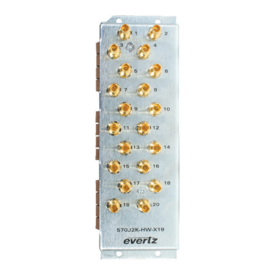
REAR AND FRONT PLATE The rear plate of 570REM-TX8-10GE is equipped with 20 Mini-Din connectors. Figure 2-1 : 570REM Rear Plate The front plate of 570REM-TX8-10GE has 12 available SFP slots. These SFP slots can be populated with SFP10G-TR13-A. Page 3... -
Page 12: Connecting Via Fc Proxy
2.2. CONNECTING VIA FC PROXY The control of the 570REM-TX8-10GE can be done through FC proxy. To configure a FC proxy address for the 570REM-TX8-10GE, log into the 570FC webpage using root and Evertz for username and password respectively. Navigate to the slot that houses the 570REM-TX8-10GE and enable the Proxy Mode Address and configure Address, Netmask and gateway for the required Control Connection. -
Page 13: Hardware Installation
ESD strap be worn. Locate on the chassis 2 adjacent vacant slots. Unpack the 570REM-TX8-10GE and separate the rear panel from the main card. Locate on the rear of the rack the two slots and remove the blanking panels. - Page 14 570REM-TX8-10GE User manual This page left intentionally blank Page 6 Revision 1.0...
-
Page 15: Specifications
570REM-TX8-10GE User manual SPECIFICATIONS 3.1. SERIAL DIGITAL VIDEO Standards: • SMPTE 424M (3Gb/s) • SMPTE 292M (1.5Gb/s) • SMPTE 259M (270Mb/s) 3.2. SERIAL VIEDO INPUT Number of Inputs 8x SDI Connector Input Equalization Automatic to 100m @ 3 Gb/s, 150m @ 1.5 Gb/s and 350 @ 270Mb/s Return Loss >15dB up to .5 GHz... -
Page 16: Physical (Number Of Slots)
3.8. ENCLOSURES 570FR 3RU Chassis 1RU Chassis Ordering Information 570REM-TX8-10GE: 8x J2K Encoders and SMPTE ST 2110 Encapsulation Paths driven by 2x UHD or 8x 3G SDI Inputs, 6x 10GbE SFP Cages SFP Modules: • SFP10G-TR13-A 10GbE Optical SFP+ •... -
Page 17: Web Interface
570REM-TX8-10GE User manual WEB INTERFACE The 570REM-TX8-10GE series of products are controlled using Web Interface. WebEasy operates using Ethernet and SNMP control protocols. Login After the card has been installed and configured with the required network addresses, it can be completely configured using the web interface. -
Page 18: Figure 4-2 : Webeasy - 570Rem-Tx8-10Ge Main Menu
570REM-TX8-10GE User manual Figure 4-2 : WebEASY - 570REM-TX8-10GE Main Menu ® Page 10 Revision 1.0... -
Page 19: System
570REM-TX8-10GE User manual 4.1. SYSTEM Figure 4-3 : WebEASY - System (Part 1) ® Card Alias: This parameter indicates the card alias string. 4.1.1. Control Port Configuration IP Address: This parameter allows the user to set IP address for control port. -
Page 20: Data Port Configuration
570REM-TX8-10GE User manual 4.1.2. Data Port Configuration For SFPP 1-6: IP Address: This parameter allows the user to set the IP address for Data port. Netmask: This parameter allows the user to set the Netmask for Data Port. Gateway: This parameter allows the user to set the Gateway for Data Port. -
Page 21: Sfp Monitor
570REM-TX8-10GE User manual Figure 4-4 : WebEASY - System (Part 2) ® 4.1.4. SFP Monitor SFP Part Number: This parameter indicates the part number of SFP. SFP Type: This field indicates the type of SFP. SFP Rx Power Level: This field indicates the received power level of SFP. -
Page 22: Configuration Management
570REM-TX8-10GE User manual 4.1.6. Configuration Management Export Configure File: The download button allows the user to download a configuration file and export it. Import Configure File: The Choose file section allows the user to select and upload a configuration file. -
Page 23: Product Features
570REM-TX8-10GE User manual 4.2. PRODUCT FEATURES Figure 4-5 : WebEASY - Product Features ® 4.2.1. License Control Product Serial Number: This parameter displays the card serial number same as the card MIB control. This is needed for the webpage. Product Mac Address: This parameter displays the card MAC address. -
Page 24: Sdi Input Control
570REM-TX8-10GE User manual 4.3. SDI INPUT CONTROL Figure 4-6 : WebEASY - SDI Input Control ® 4.3.1. Input Status Input Alias: This control allows the user to set an alias name for input. Video Standard Detected: This parameter displays the detected video standard of SDI input. It’s not available if input is ASI. -
Page 25: Ip Output Control
570REM-TX8-10GE User manual 4.4. IP OUTPUT CONTROL Figure 4-7 : WebEASY - IP Output Control ® 4.4.1. Configuration IP Output: This dropdown allows the user to configure how to process the incoming streams into the outgoing streams. 4.4.2. IP Output Control For SFPP 1 to 6: IP Output Enable: This is for enable/disable output. -
Page 26: Encoder Control
570REM-TX8-10GE User manual 4.5. ENCODER CONTROL Figure 4-8 : WebEASY - Encoder Control (Part 1) ® 4.5.1. Encoder Configuration Latency Mode: This control allows the user to set the latency of the encoding process. It should be displayed if any product feature support J2k Encoder is enabled and the number of index to be displayed depends on the number of J2K enabled. -
Page 27: Encoder Audio Output Control
570REM-TX8-10GE User manual Max Video Bit Rate: This parameter displays video TS bitrate. Note: Card will adjust the bitrate for video and other pids based on these settings. Unit is kbps. Number of Stripes: This parameter displays the number of stripes. -
Page 28: Compliance
4.5.4. Compliance Compliance Mode: This dropdown allows the user to set the standard that the encoders are running based on them. Applicable options include Normal, TR01 and Evertz legacy. 4.5.5. Encoder Reference PCR Control Jitter Tolerance: This dropdown allows the user to set the jitter tolerance for the master PCR time reference. -
Page 29: Ptp And Master Pcr Control
570REM-TX8-10GE User manual 4.6. PTP AND MASTER PCR CONTROL Figure 4-10 : WebEASY - RTP and Master PCR Control ® 4.6.1. PTP and Master PCR Control PTP or Master PCR Selection: This parameter allows the user to select the reference as either PTP or Master PCR. -
Page 30: Ptp Control
570REM-TX8-10GE User manual 4.6.2. PTP Control Domain Number: This control allows the user to set the domain number. 4.6.3. Master PCR Control IP Address: This field allows the user to set the IP address from which to obtain the Master PCR time reference. -
Page 31: Breakway Audio Ip Output Control
570REM-TX8-10GE User manual 4.7. BREAKWAY AUDIO IP OUTPUT CONTROL Figure 4-11 : WebEASY - Breakaway Audio Input Control ® 4.7.1. Breakaway Audio Breakaway Audio Enable: This field allows the user to enable/disable sending audio groups to separate IP and port destinations. -
Page 32: Mosaic Control
570REM-TX8-10GE User manual 4.8. MOSAIC CONTROL Figure 4-12 : WebEASY - Mosaic Control ® 4.8.1. Mosaic Configuration Output Video Standard: This dropdown allows the user to set the output video standard. 4.8.2. Mosaic Audio Bar Overly Audio Bar Overly: This parameter allows the user to enable/disable the Audio Bar Overlay. -
Page 33: System Notify
570REM-TX8-10GE User manual Received Bandwidth Threshold: This parameter allows the user to set the received bandwidth threshold. 4.9.2. System Notify System Traps: This dropdown is used to turn traps on and off. System Faults: This control checks whether a fault is currently present or not. -
Page 34: Firmware Upgrade
® 570REM-TX8-10GE modules. On the top of the web page for the 570REM-TX8-10GE modules, there is a button labeled Upgrade. The Upgrade tab is used to check current firmware version and upload the latest firmware (Figure 5-1). Figure 5-1 : WebEASY - Upgrade Button on Top Menu Bar ®... -
Page 35: Figure 5-3 : Webeasy - Firmware Upgrade Menu\Selecting Firmware File
570REM-TX8-10GE User manual Figure 5-3 : WebEASY - Firmware Upgrade Menu\Selecting Firmware File ® Once selected, click open to advance to next step. Click upgrade and watch progress bar for status. Once completed, the device will automatically restart. Page 27... - Page 36 570REM-TX8-10GE User manual The End Page 28 Revision 1.0...
Need help?
Do you have a question about the 570REM-TX8-10GE and is the answer not in the manual?
Questions and answers